You are using an out of date browser. It may not display this or other websites correctly.
You should upgrade or use an alternative browser.
You should upgrade or use an alternative browser.
Sprinter 4WD Conversion Idea, GMT-800 IFS.
- Thread starter luthj
- Start date
luthj
Engineer In Residence
Welder... Is your wire rusty? Liner dirty from old wire? Those 2 things will make any mig hateful. IF you don't use it all the time, these things happen.
Years ago I just borrowed a friend or my works welder. But when I moved I needed something cheap to do a few brackets etc for my van conversion, so I got a refurb 115V flux core unit. It worked surprisingly well with quality wire. It won't sustain an arc currently, not sure if its worth messing with, as I am going to order a decent MIG shortly. Though I do need to sell it...
-----------------
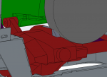
I shifted the diff to the left half an inch, and got some more measurements of the bell housing placement. Still looks like significant interference, but I am being conservative with my diff measurements. Most of the interference is boss/webbing material on the diffs inward face. So it could be clearance ground with minimal impact on strength. There is a bit of extra meat on the bell which could be removed. Not sure what I want to do at this point. Dropping the subframe any further Fubars the UCA mount placement (due to anti dive and the lateral members which are shared). I could shift the diff another 3/8" to the right. That may be in the plunge CV bind rage. Mesuring CVs with stiff boots is quite challenging I have found.
The rest of the subframe is looking good, just tweaking stuff to make it easier to mfg (reducing nested features etc).

luthj
Engineer In Residence
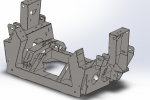
Spent most of the day beating on the subframe design. Its very close I think. I need to verify some measurements for sanity sake. I think I will slot a the engine mount holes, and maybe a few other locations. Now, the important question. Do I want to add a hard point for recovery?

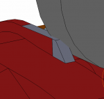
Interference is down to a reasonable level. I think I can grind enough to get clearance here. I dropped the subframe 3/8". So the final lift is closer to 3" from stock. I also widened the track 1/8" to give some clearance for the shock towers to the fender walls. I wan't to avoid the BFH as much as possible.


Interference is down to a reasonable level. I think I can grind enough to get clearance here. I dropped the subframe 3/8". So the final lift is closer to 3" from stock. I also widened the track 1/8" to give some clearance for the shock towers to the fender walls. I wan't to avoid the BFH as much as possible.

shade
Well-known member
I was thinking about your sub-frame while mowing. As far as using it for a lift point, it might be worthwhile painting the lower portion yellow to make it clear when you say, "Don't put a jack on that yellow part," that you mean not to lift from any of it.Do I want to add a hard point for recovery?
I'd be concerned with an aggressive recovery screwing up some aspect of the alignment of the sub-frame and driveline. With as tight a fit as you have, one off-axis tug might spell disaster unless you're confident that it'll hold up to a less than optimal recovery attempt.
I am going to order a decent MIG shortly.
With the edges the way you have it drawn, I would really recommend getting a TIG. You did not leave a gap for filler that a MIG would require for a good weld. Everything would need to be welded on the inside of the edges for strength. There are a lot of places on that where that will not be possible.
luthj
Engineer In Residence
My reference materials indicate 1/16-3/32 gap for 1/4" butt welds. I did leave a bevel gap on the frame plates. My initial thoughts were 2-3 times the wire diameter? Just guessing though. My initial plan was to do inside corner welds for most of the internal parts, and then put the outer plates on. The cross-over tubes can't really have internal welds on 3 sides. Hmmm, I can gap those, or spend a few hours beveling the edges I guess. I would probably do that regardless of what weld process I use, just to reduce heat input required for good penetration.
I expect I will need to do lots of stitch style welding, otherwise the HAZ will get pretty large, and distortion may get significant.
I don't think I need 100% penetration in most of the weld seams, but there are several spots where I will need to pay close attention (shock towers, rear LCA anchors).
luthj
Engineer In Residence
Alloy
Well-known member
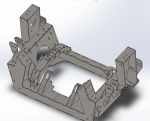
I'm trying to clicking on the image to zoom in and see different perspectives....nothing happensSoooon. Final body count is 79. Total unique parts is about 45. Weight sans welds is 167lbs. I am going to verify the engine mount position and subframe bolts one last time. Then export all the bodies, and start making DXFs and BOM for quoting. I just need to come up with a part numbering scheme.
View attachment 539332
Where possible extend the bracket to the edge and make the end 1/8"-1/4" high not a point. Brackets/gussests that end in middle of a plate will allow flex.
Does the bottom have lightening holes it won't fill with dirt?
luthj
Engineer In Residence
That is just a screenshot. I can upload a couple of standard views if folks want to review. I could make an E-drawing, but you would need to install the solidworks viewer to look at it. There is drain/lightening holes in the bottom side of all the tubes. That will also make inside painting a bit more reasonable.
DaveInDenver
Middle Income Semi-Redneck
Why not a 3D PDF?That is just a screenshot. I can upload a couple of standard views if folks want to review. I could make an E-drawing, but you would need to install the solidworks viewer to look at it. There is drain/lightening holes in the bottom side of all the tubes. That will also make inside painting a bit more reasonable.
luthj
Engineer In Residence
Why not a 3D PDF?
I didn't realize solidworks could do that now. I only recently upgraded from the 2009 release...
Similar threads
- Replies
- 1
- Views
- 537
- Replies
- 12
- Views
- 2K
- Replies
- 0
- Views
- 388
- Replies
- 1
- Views
- 1K
- Replies
- 17
- Views
- 1K

