Sprinter 4WD Conversion Idea, GMT-800 IFS.

luthj

Engineer In Residence
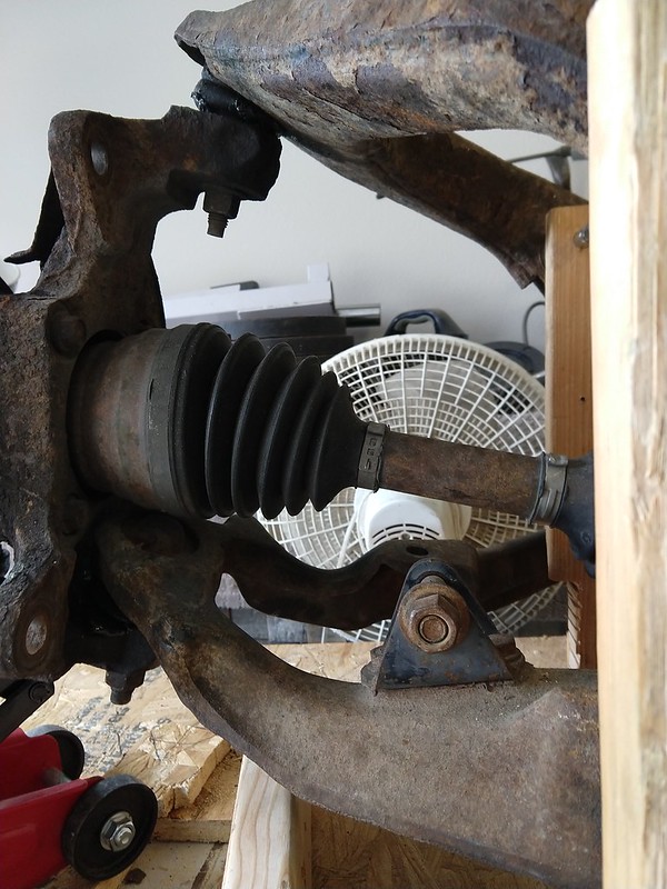
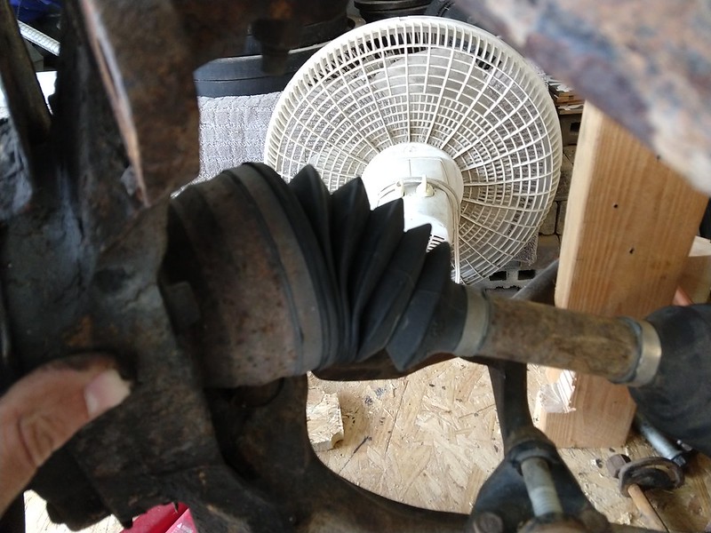
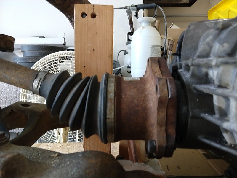
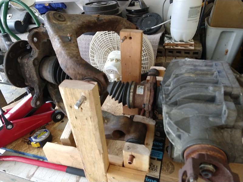
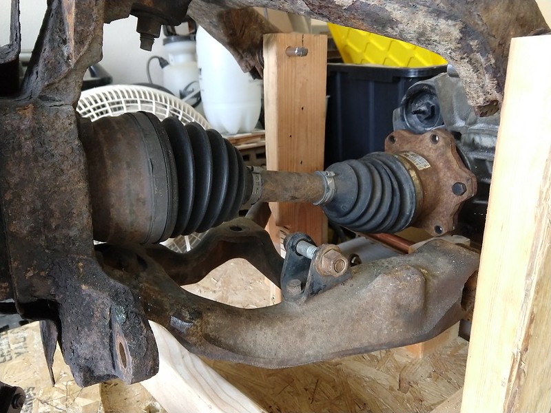
Put the diff on the jig table. Ran the CVs and BJs through the range. The boots don't like it, but the outer CVs will do 50 degrees. That is full lock and bump. Despite widening the suspension from stock, the inner CVs appear to have enough plunge. If its marginal, I will just add a spacer. Several folks make them, so shouldn't be an issue.


506999
 
Last edited:

luthj

Engineer In Residence
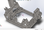
A bit of a design milestone. So I decided to step back and evaluate some specifics. The subframe consists of 72 parts (not counting hardware). About 32 unique parts total. It weighs ~150lbs. Which combined with the GM bits and coilovers, will add about 250lbs to the front axle. The vans front axle currently sits at 3,700lbs fully loaded. So Estimated axle weight is ~3,950lbs. Though I hope to cut a few hundred pounds by moving some weight in the cargo, and lightening my galley cabinet. It should be obvious why I chose the 2500 suspension, as the 1500 would simply be outclassed by the load.

Corner weights are thus around 1850lbs, Motion ratio is 1.7:1, and the shocks have about 4.6" of travel. With 3.5" of travel in droop, I have a wheel rate of about 530lb/in. The static load at the spring is 3,150lbs. With 1" of preload, the math works out to 3150/(2.1+1)= 1000lbs. Which is pushing the limits for a 3"ID spring. I don't see any greater than 800lb/in listed on most vendors catalogs. There are 1000lb/in springs in the 2.5" ID at 12" lengths. I suspect I may be running up against the limits of wire size and torsion. I might be able to get custom springs made, but that's not me preference. I could go with 2" of preload, which would drop the spring rate to ~750lbs. That may be the route I go with. Thats a fair bit of load on the droop stop, and a good workout to preload the spring. I think 750 would be too soft, even with a stiff sway bar. So I will likely go with the highest off-shelf rate available. Springs are not expensive, so I can swap down the line.

Given the 3,000lb static load, I am considering making a bracket to tie the top of the shock tower to the sprinters strut brace. Its about 1/16 thick formed steel, so should take a bolt well.


507223

You will also notice a lot more slots/tabs. I just surpassed 100 sets. It got bad enough that I just made a folder to hold them all, as my feature tree was way to long to scroll through.
 
Last edited:

b dkw1

Observer
The closer you can get to zero preload, the better off you will be. Shock tower brace is an excellent idea.

Are there any parts like the "frame rails", shock towers or the cross members that you could bend and combine 2 parts? It would cut down on assembly time quite a bit.
 

luthj

Engineer In Residence
The closer you can get to zero preload, the better off you will be. Shock tower brace is an excellent idea.

Are there any parts like the "frame rails", shock towers or the cross members that you could bend and combine 2 parts? It would cut down on assembly time quite a bit.

Yeah, it's a bit of a balancing act. With the 2.5s I can run higher damping rates for high speed, so bottom out is less of an issue. Based on some anecdotal feedback from other people running GMT 800 IFS converted to coils, 1200lb rate springs are a bit on the light side. Most of those folks are low budget, so they are running dual tube shocks with much lower max damping. Supposedly this company offers 3x12 and 3x14 coils up to 1100lb rates. Not cheap at 130$ each, but should get me in the ballpark.
https://www.purplespring.com/produc...er-springs-3-id-12-free-length-rates-50-1110/

I am a bit concerned that the van will be a bit of a pig, wallowing about on too-light springs. Which is about how it handled prior to adding Fox 2.0s with lots of low speed damping.

The other consideration is that I can add some stiffer bump-stop rubbers to make the rate progressive.


I have been tempted to make extensive use of a press break, but doing the assembly myself (or as a kit) it makes more sense to go with minimal bending. Given I will likely only sell a handful of these if I am lucky. Labor of love (obsession? boredom?)!


After looking at the destruction bestowed upon 5/8" shaft shocks (arguably by abusive driving). I am pretty set on the 7/8 2.5 shocks.

https://expeditionportal.com/forum/...1500-budget-low-lift-with-37-s.166120/page-39
507462
507463
507464

The OP of that thread likes to bash the GM 2500 as overbuilt. The cognitive dissonance is pretty startling given how much of the lighter duty 1500 running gear he breaks.
 
Last edited:

b dkw1

Observer
I tried to help that guy, he did not want to listen. He was doing just about everything wrong then tried to blame it on the shocks.
 

luthj

Engineer In Residence
Yeah, Dunning-Kruger effect is a hellava drug... I have seen locals in Mex, Honduras, even Aus rocking unmodified or lightly modified LCs and hilux over stuff that would make most of us pucker in fear. All of it for 10s of thousands of miles without breakage. The truck doesn't make the driver, the driver brings out the best in the truck.

I have a friend, that after something like 15 years, and innumerable broke suspensions/wheels/tires, FINALLY started airing down when he hit the dirt. It's crazy, but it was a point of pride that he didn't need it!
 

b dkw1

Observer
Where are you located? The sheetmetal shop I used in SoCal would laser cut parts and break them for a pretty reasonable price.

http://rimetal.com/

They do a LOT of parts for a lot of off-road shops in the SoCal area. Getting a knock down kit from them is pretty easy. Having a few bends in there would really cut down on the amount of welding and assembly time.
 

luthj

Engineer In Residence
I am currently job hunting in a good potion of the American West. So when I land one I will know where I am!

I have not done a lot of sheetmetal design work. Normally I would consult the shop engineer/foreman's notes on bend allowances. When making a design to bid out, Do you just take a guess at the K factor, and hope the shop gets it right?

It's been a few years since I used solidworks for multi-body work. So It will be significant hours to rework the model into formed sheetmetal. If I had decided to build with that in mind it would be a different matter. A learning curve indeed.
 

Len.Barron

Observer
You're not going to ever build this in enough quantity to worry about forming vs weldment, and just from looking at the make up of the pieces you wouldn't see much advantage to try and start from extruded shapes. I'd stick with jet/laser cut plate with alignment tabs and weld relief notches. You'll keep scrap to a minimum and any rework/redesign to individual sections will have minimal impact/effort to accomplish.
 

b dkw1

Observer
Ahhhhhh, my SW skills are more than a little rusty. Quick google cheat shows you can convert them to sheet metal parts pretty easy and joining them isn't much harder. The K factor .447

A good shop will know if you have screwed the pooch on anything and call you about it.

When My buddy Craig worked at R&I i would send him files like that and he would go through a insert the bends to join multiple pieces. He would then call and tell me how bad I sucked at SW. He was not wrong.
 

luthj

Engineer In Residence
I am a bit stalled on the subframe until I tear my van apart a bit. So I am digging into the low range fix.

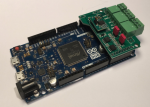
I found this example of a CANbus bridge using the arduino Due hardware.
https://copperhilltech.com/blog/can-bus-bridge-cantocan-application-with-arduino-due/

509806

The author kindly provides a sample sketch (attached zip). I am a rank amateur at arduino coding (and C in general). But I think the code base can be adapted to what I need to do. At about 90$, its not terribly expensive, and has lots of functionality if I need other functions.

My research indicates that I need to modify CAN frames 0x200 for front wheels, and 0x208 for the rear wheels. The frame ID is 11 bits. The wheel speeds are stored as 16 bit values. Left wheels are in data bytes [4]..[5], and right is in [6]..[7] I don't know how the values are represented (RPM?, Pulses per second?). It doesn't matter much really. I just need to get the endian-ness right, and divide by 2.73.

So I need the program to match the frame ID with a table. If in low range, and the ID matches hex 200 or 208, modify bytes 4-7. All others are re-transmitted unmodified.
 

Attachments

  • CAN_CAN_Bridge.zip
    17.9 KB · Views: 0

luthj

Engineer In Residence
Digging into the code a bit, here is the relevant main loop. I have started annotating and modifying it for this application. Essentially it reads the CAN mailboxes on both CAN segments. If the messages ID matches, and low range is on, the bytes are modified and transmitted. Otherwise they are just transmitted unchanged. I still need to write the code to perform the speed division, and modify the Data array. I am not sure what the best way to modify the bytes in question. They are probably unsigned 16bit integers, but I haven't determined the endianness, either of the array, or the frame itself. Only 4 possible combinations, might be easier just to do a trial and error approach...

C++:
void loop()
{
  // Declarations
  byte cPort, cTxPort;
  long lMsgID;
  bool bExtendedFormat;
  byte cData[8];
  byte cDataLen;
  int lowrange;
 
  // Start timer for LED indicators
  TimerStart(&pTimerLEDs, TIMER_RATE_LED_BLINK);

  while(1)  // Endless loop
  {
    // Control LED status according to CAN traffic
    LEDControl();
    
    //Read low range switch and assign to lowrange varaible
    lowrange=digitalread(LRSW);
    
    // Check for received CAN messages
    for(cPort = 0; cPort <= 1; cPort++)
    {
        
      if(canRx(cPort, &lMsgID, &bExtendedFormat, &cData[0], &cDataLen) == CAN_OK)
      {
        // Scan through the mapping list, If frame matches ID and lowrange is high.
        for(int nIndex = 0; nIndex < nMappingEntries; nIndex++)
        {
          if(lMsgID == CAN_DataMapping[nIndex].lReceivingMsgID
                // Removed matching for source CAN port
                // && cPort == CAN_DataMapping[nIndex].cReceivingPort
                && lowrange == 1
             )
          {
            //If recieved port is CAN0, transmit on CAN1, otherwise transmit on CAN0.
            cTxPort = 0;
            if(cPort == 0) cTxPort = 1;
            //Wheel speed conversion
            
              // Transmit Frame, print error message if CAN_ERROR is returned
            if(canTx(cTxPort, CAN_DataMapping[nIndex].lTransmittedMsgID, bExtendedFormat, &cData[0], cDataLen) == CAN_ERROR)
              Serial.println("Transmision Error.");
          
            
          }
          //Transmit Frames If low range is not active, or for non-matching frames
          else {
                //If recieved port is CAN0, transmit on CAN1, otherwise transmit on CAN0.
                cTxPort = 0;
                if(cPort == 0) cTxPort = 1;
                (canTx(cTxPort, lMsgID, bExtendedFormat, &cData[0], cDataLen) == CAN_ERROR)
                Serial.println("Transmision Error.");
                }// end if else
          
        }// end for
 
      }// end if

    }// end for
    
  }// end while

}// end loop
 
Last edited:

luthj

Engineer In Residence
Some tangentially related news. My wife and I just accepted job offers in Charlotte NC, starting immediately. So we will be making the move out that way in the near future. Looks like that will be our home for a few years. The good news is that I will hopefully have a garage at some point. Though if we get stuck in an apartment, that may be for several months.


On the CANbus code front, I am about 90% done with a draft program. This one should pass all frames between the segments. For 0x200 and 0x208 it will read the relevant bytes into integer variables and divide by 2.73 (when low range pin is high). For frame 0x200 there is an average speed for the front wheels in bytes 2-3. I am not sure if this is used by the TCM or not. I don't think the rear wheel frame (0x208) has an average value in the frame. I won't know until I do some testing, and capture some of the relevant frames. The program is setup to print relevant values to the serial line, so I can monitor via a computer.

Other tidbits; the values from the frames are little endian (lowest value byte first). So is the Due controller I am writing code for.

C++:
void loop()
{
  // Declarations
  byte cPort, cTxPort;
  long lMsgID;
  bool bExtendedFormat;
  byte cData[8];
  byte bData[4];
  byte cDataLen;
  int lowrange;
 
  // Start timer for LED indicators
  TimerStart(&pTimerLEDs, TIMER_RATE_LED_BLINK);

  while(1)  // Endless loop
  {
    // Control LED status according to CAN traffic
    LEDControl();
   
    //Read low range switch and assign to lowrange varaible
    lowrange=digitalread(LRSW);
   
    // Check for received CAN messages
    for(cPort = 0; cPort <= 1; cPort++)
    {
       
      if(canRx(cPort, &lMsgID, &bExtendedFormat, &cData[0], &cDataLen) == CAN_OK)
      {
        // Scan through the mapping list, If frame matches ID and lowrange is high.
        for(int nIndex = 0; nIndex < nMappingEntries; nIndex++)
        {
          if(lMsgID == CAN_DataMapping[nIndex].lReceivingMsgID
                // Removed matching for source CAN port
                // && cPort == CAN_DataMapping[nIndex].cReceivingPort
                && lowrange == 1
             )
          {
            //If recieved port is CAN0, transmit on CAN1, otherwise transmit on CAN0.
            cTxPort = 0;
            if(cPort == 0) cTxPort = 1;
           
            //Initialize wheel speed int to zero
            short wSpeedL = 0;
            short wSpeedR = 0;
            short wSpeedA = 0;
           
            //copy speed data bytes to working array from CAN data array
               bData[0] = cData[4];
              bData[1] = cData[5];
              bData[2] = cData[6];
              bData[3] = cData[7];
             
            //Set wSpeed to array data
              wSpeedL = (wSpeedL  << 8) + bData[0];
              wSpeedL = (wSpeedL  << 8) + bData[1];
              wSpeedR = (wSpeedR  << 8) + bData[2];
              wSpeedR = (wSpeedR  << 8) + bData[3];
             
              //print data for debug
              Serial.print("wSpeedL raw =");
              Serial.println(wSpeedL);
              Serial.print("wSpeedR raw =");
              Serial.println(wSpeedR);
             
              //For Front wheels, frame 0x200, adjust front wheel average speed.
              if (lMsgID == 0x200)
                    {   
                        // copy speed data to wSpeedA
                        wSpeedA = (wSpeedA  << 8) + cData[2];
                        wSpeedA = (wSpeedA  << 8) + cData[3];
                       
                        //debug printing
                        Serial.print("Front average speed CAN Raw, cData[2]..[3] =");
                        Serial.print(cdata[2], HEX);
                        Serial.println(cdata[3], HEX);
                        Serial.print("wSpeedA = ");
                        Serial.println(wSpeedA);
                       
                        //divide average speed
                        wSpeedA = (wSpeedL/2.73);
                       
                        Serial.print("wSpeedA divided = ");
                        Serial.println(wSpeedA);
                       
                        //Copy revised speed to data array
                        void memcpy (cData[2], (byte*)&(wSpeedA),sizeof(wSpeedA));
                       
                        Serial.print("Front average speed Converted Raw, cData[2]..[3] =");
                        Serial.print(cdata[2], HEX);
                        Serial.println(cdata[3], HEX);
                    } //end if
                   
              //Divide Wheel speeds by 2.73
              wSpeedL = (wSpeedL/2.73);
              wSpeedR = (wSpeedR/2.73);
             
              //print data for debug     
              for (int mIndex=4; mIndex <= 7; mIndex++)
              {
                  Serial.println("cData [4]..[7]");
                  Serial.print(mIndex);
                  Serial.print("-");
                  Serial.println(cdata[mIndex], HEX);
              }//end for loop
             
              //Copy wSpeedL and wSpeedR to working array, Note offset for start byte.  Assumes both CAN frame and chip are little endian
              void memcpy (bData[0], (byte*)&(wSpeedL),sizeof(wSpeedL));
              void memcpy (bData[2], (byte*)&(wSpeedR),sizeof(wSpeedR));
             
              //Print working array contents
              for (int mIndex=0; mIndex <= 3; mIndex++)
              {
                  Serial.println("bData[0]..[3]");
                  Serial.print(mIndex);
                  Serial.print("-");
                  Serial.println(bdata[mIndex], HEX);
              }//end for loop
             
             
              //Copy bData to data array
              cData[4] = bData[0];
              cData[5] = bData[1];
              cData[6] = bData[2];
              cData[7] = bData[3];
             
           
              // Transmit Frame, print error message if CAN_ERROR is returned
            if(canTx(cTxPort, CAN_DataMapping[nIndex].lTransmittedMsgID, bExtendedFormat, &cData[0], cDataLen) == CAN_ERROR)
              Serial.println("Transmision Error.");
         
           
          }
         
          //Transmit Frames If low range is not active, or for non-matching frames
          else {
                //If recieved port is CAN0, transmit on CAN1, otherwise transmit on CAN0.
                cTxPort = 0;
                if(cPort == 0) cTxPort = 1;
                (canTx(cTxPort, lMsgID, bExtendedFormat, &cData[0], cDataLen) == CAN_ERROR)
                Serial.println("Transmision Error.");
                }// end if else
         
        }// end for
 
      }// end if

    }// end for
   
  }// end while

}// end loop
 
Last edited:

luthj

Engineer In Residence
Thinking about my front tone ring considerations. The GM rings use 55 teeth, MB uses 44. I need to either make replacement tone rings (external to the hub integral ones), or do some electronic wizardry to translate the signal.

Both GM and MB use passive inductive sensors. A permanent magnet is wrapped in a wire coil, both ends are returned to the ABS control unit. When rotating, the wheel induces an AC signal in sensor wires. This is about 0.5-3VAC. The ABS unit is likely going to see about 5-20mA of current for sensing purposes.

The control unit is going to count the number of pulses to determine wheel speed. My thoughts on a electronic solution.
Arduino or similar. Input the GM speed sensor through a analog comparator. Set the comparator to flip when the voltage passes ground (zero) with one end of the sensor tied to ground. The arduino will measure frequency using the pulsein or freqcounter functions.

The output is a bit trickier. The MB ABS module checks for the sensor (about 2k ohm) at startup. So I will need to wire a matching resistor to keep it happy. It would be great if the ABS module was happy with a square wave from 0-5V or so. Otherwise I will need a square wave with both positive and negative excursions. That would require some transitors and 2-3V DC supply as the "ground" for one of the pins.

As far as the program goes, I am thinking a single loop with timer. Say 10 times a second the program records 8ms of input (or maybe 8-10 pulses?). This is saved in a array for later reference. The frequency of the pulses is calculated, divided by 1.25, then fed to the PWM output pins. The PWM output produces a continuous stream of digital pulses at the desired frequency, which drives an array to produce a AC square wave in the 2-5V range.
 
Last edited:

luthj

Engineer In Residence
I got some dimensions on 3.0x14" coilover springs. 1000lbs is 4.75, 1,100 is a bit bigger. 1200lb or higher is a special order (quite pricey). I added a lateral offset to the lower shock bracket. Its about 1", which yields an effective motion ratio of about 1.6:1. The shock travels 5", and the wheel around 8". With an 1100lb spring, I would need about 1.7" of preload for 3.5" of droop. Not ideal, but worth trying. I can always go for a 1200lb custom spring if necessary. Of course having the shock lower moved out 1" means the UCA need more clearancing. I am thinking I will make a pair of 1/4" steel plates, that will weld to the top/bottom of the UCA. Then just follow the edge profile to remove the interfering material. At the thinnest point, the UCA will be around 0.5", which should be okay.

511324
 
Last edited:

Forum statistics

Threads
188,170
Messages
2,903,040
Members
229,658
Latest member
rjparnow415
Top