The 50 dollar dual-battery thread is golden, and great for simple auxiliary battery charging, but It pays to know what you have to begin with. Either you have a charging system with a high enough voltage or you don’t. If you don’t, either boost the alternator’s charging voltage somehow or use other charging systems with the required higher voltage. If you have the higher voltage, you have amps flowing or you don’t. You don’t know how many charging amps are flowing unless you measure it. Installing the 50 dollar special does not guarantee high current/amps house battery charging from the alternator even if it has the required high voltage..
Using the alternator for charging an auxiliary battery with a solenoid/isolator OR a DC-DC booster can really tax the alternator.
Probably TL;DR. I’m not a Legitimate ExPo Guy, and basically interested in keeping a 12v fridge running with a simple system. This is not for the highly technically skilled posters who’ve advanced way beyond my needs and experience, and surely needs editing.
The values below are from over three years ago, old man memory, might not jive mathematically, and are meant for system operation rather than specifics.
I purchased a 1994 Econoline with a factory installed simple solenoid-connected system that seemed to be the fifty dollar special, and a 130 amp alternator that maxed out at 14.8vdc. The voltage reduces magically to about 14.0 when both batteries are charged and everything’s heated up. Batteries up front on both sides, connected with a #4 copper wire. 100ah AGM for house. Solenoid energized except in OFF and START. I later found out why the batteries aren’t connected in START. I installed a toggle switch to turn off the solenoid when desired.
Happy, lucky me until noticing that when the house battery needed full charge, the voltage measured from start to house battery positive posts was .6vdc or so, or the house battery read .6vdc less than the charging battery.
That made it seem the solenoid’s contacts were iffy, causing a resistance, reduced amp flow and power loss. The continuous duty solenoid is hidden underneath the start battery’s box, accessible by removing the headlamp and looking through a fist-sized hole behind it. I finally noticed the smallish (no larger than #10) yellow wire on the main contact right side. The other side has the red #4 headed to the house battery. ?????? Picture below.
I “won” a 1994 EVTM (wiring) manual and discovered the yellow wire on the solenoid was fed from a hot all the time 60 amp fuse “T” in the engine fuse panel. DC voltage measured directly across the solenoid’s contacts at maximum charging read .009VDC. Good contacts. The drop of .6VDC measured from battery to battery was actually due to resistance from the fuse box source to the solenoid on that small yellow wire instead of across the contacts. It seems the Ford designers deliberately undersized the yellow wire for resistance to limit current flow and the fuse made sure it didn’t rise above 60 amps maximum. That 130 amp alternator suddenly seemed much smaller. Diagram picture below.
Then it got worse. My biggest mistake was not measuring actual current flow to the house battery when maximum charging was needed as step #1. Stupid me. Without knowing actual DC charging amps, everything else is speculation. That importance of measuring amps is mentioned more in older threads, but not so much recently in the DC to DC charging/solenoid/isolator debates. Whatever system is used, device amp ratings or voltages mean little if the amps aren’t flowing.
My 100 amp hour AGM will accept amps in the mid-upper forties connected to a 14.8vdc source with heavy cables when down about 12.2vdc, but that charge current goes down fairly rapidly to the thirties. When using the original factory supplied small yellow wire feed through the solenoid, the initial charge current is slightly less than thirty amps, and drops to about sixteen amps in short order as battery voltage/internal resistance rises and possibly the yellow wire heats up. Let’s hear it for the 14.8v, 130 amp alternator and the amp flow limiting wiring!
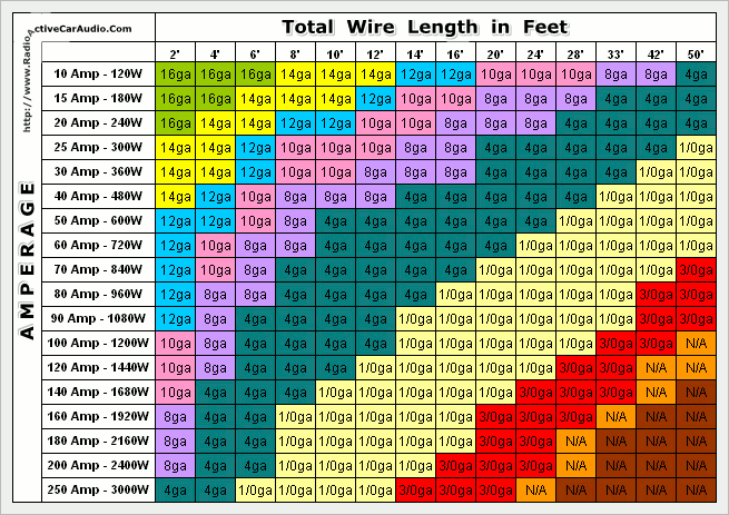
ALL of that 130 amp alternator’s possible output flows through two #12 gauge grayish fusible link wires, also in the diagram below. Go dig around the web and find out what current those fuse links can pass for how long before blowing. That is not just a Ford thing. When they heat up, they become resistors. Try to feed a too-hungry battery or accessory load, possibly poof, and you’re hoping to make it somewhere on battery power alone. I can see why sometimes links get replaced by fuses.
The next experiment was with a 2000 watt inverter connected to the house battery, with a 120vac, 500 watt floodlight load. House battery drained to about 12.2V, not connected to start battery, engine not running. DC amps from the house battery to inverter/floodlight was upper forties. Fire up the engine, and amp flow from the factory solenoid’s previous maximum of thirty amps now reads fifty-something. ?????. Getting close to the 60 amp factory fuse rating. That 60 amp fuse also probably explains why the solenoid is not energized in START. Imagine a discharged start battery.
It seems the factory system was intended for house battery charging ONLY, and not the house battery AND significant fixed loads connected to it at the same time. It seems internal battery resistance was considered and its resistance would quickly rise and amp flow fall, maybe for longer alternator life? Warranties?
Next experiment. No load on the house battery. House and start batteries both drained to about 12.2vdc, and a #1/0 AWG welding cable with clamps ready to connect as soon as the engine started. That ought to solve the voltage loss from the factory system. It did. Got almost fifty initial amps to the house battery, don’t know how much to the start battery and some protesting from the alternator, engine, and belt at idle. A hungrier battery chemistry accepting more amps could really make something angry fast.
For over three years, when needing faster charging, before leaving camp, I let the factory solenoid system bring the house battery up a little to limit the wallop to the alternator from the big cable, then close the manual 100 amp switch, and drive. Turn off the big cable when parked. That manual switch will someday be something smart. I’m becoming more forgetful.
Two digital voltmeters, both reading identically when connected to the same source, checked against a calibrated meter, now reside under the dash within eyesight. One connected to start, the other to house. It is depressing sometimes how long it takes for them to equalize. When solar voltage is greater than alternator, it’s interesting going under the shadow of an overpass. Voltage blip blip. The batteries equalize sooner via the 1/0 cable. I know how to replace the alternator, as well as the brush/regulator assembly and bearings. They are also quite inexpensive, long lived, but aggravating to repair on the road.
Measuring amp flow is critical, especially on a simple system without current monitoring. Photo of old man collection going back forty years.
When tenths of volts are important, so are accurate voltmeters. Attaching multiple voltmeters, all connected to one 12v battery, can be a real eye-opener. Most of the readouts on charge controllers and other solar doodadery I’ve seen are close. Some multimeters have adjustments inside to calibrate. My only source for comparing against a bonafide calibrated meter is at a battery supplier/starter/alternator rebuilder forty miles away I occasionally visit.
If there is ever a next time involving house/auxiliary battery charging, step #1 will be to to connect the house battery, discharged to an acceptable low voltage, connected to the start battery with the cables to be used, and measure DC current flow and voltage loss from post-to-post, while listening for engine/alternator protests. Then maybe install.
If using a DC-DC booster, are the rated amps actually flowing? Not often mentioned is that the current/amps flowing into a DC-DC boost charger can be 125% of the output. A 20 amp rated DC-DC charger could be drawing 25 amps, 40 amp could draw 50 amps from the alternator. So both an isolator/solenoid or DC-DC boost charger places strain on the alternator/belts/pulleys, and you don’t know how much strain unless amps are measured. The 50 dollar special works for my application, but charging amps to the battery aren’t known without measuring.


Found this Youtube video after typing this. It explains much better than the blather above.