this is for interest, as is - I have no intention of trying to persuade people of the effectiveness of any of the competing approaches, simply to note that they can all be made to work and all with have their own peculiar failure mode.
After more than 100,000 km on lots of rough roads with "modified 3 point mount" on MWB Fuso the chassis is intact.
I had access to both the Fuso info and the Aus body mounting guidelines plus engineering advice.
I have extra support evenly spaced. Imagine 7 "mounts". Front pair are simple compression springs. Next pair are "fixed". Next pair are simple compression springs. All "outrigger". Last one is pivot. The pivot is central between the chassis rails (rather than above) to avoid lateral movement of the pivot due to twisting of the chassis.
The compression springs are rated and compressed just sufficiently to share the load. They are long enough and of a rating that the small amount of compression/expansion has little effect on how much of the load they carry. Hooke's law for the engineers. 10mm wire, 7 turns, 300mm long, 75mm OD, compression/expansion <15mm, static load on each mount around 110kg.
The box is lightweight with a drop top. Its "post compressed" to provide rigidity but nevertheless I didn't want to subject it to any twisting. I didn't need or want to have passengers in the rear while driving. All up weight is around 4500kg.
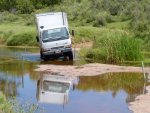
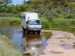
Interesting bit for the discussion is that the chassis twist is less when there is weight on the springs, the springs "work" rather than the chassis. Memory fading, I think I allowed for clearance at 15 degrees of chassis twist but doubt it ever gets that far. A 6000 kg vehicle would probably twist less and have more leaf spring movement than my 4500kg vehicle.
In the photos below the vertical exhaust at left rear corner of cab (when facing forwards) gives a clue to the angles. Coming out of Palm Valley (central Aus) about 3 1/2 years ago. A few holes in the sandstone under the water.
Also interesting while driving is the bend in the chassis rails that is visible as the top of the cab becoming closer to the box. I spent a lot of time watching commercial heavy vehicles flex in that way so am relatively happy.
My understanding of crawl throughs is that the bellows is wont to pull out of its mounts in extreme conditions on "fixed" mounts but I don't have a crawl through so its just heresay.
My sub-frame broke in Mongolia but that's another story, wasn't a show stopper, and unrelated to the mounting. The reason for the break is unique to me and my vehicle (chassis rails truncated immediately behind rear spring hangers by previous owner so long cantilever to spares and heavier wheels as original design around standard wheels).
My impression of the Hackney design is that the three points were at the forward extremity of the body and the rear extremity of the chassis which allowed the chassis to bend, possibly a bit like the high frequency oscillations of IainC's(?) Merc front springs on the recently posted video. Classic fatigue.
View attachment 243844View attachment 243845


