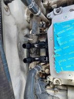
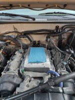
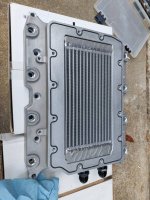
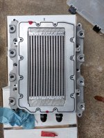
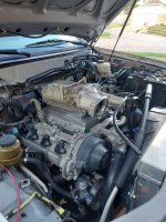
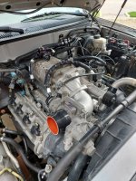
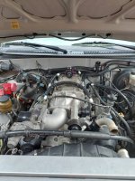
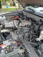
Yes, it's a basket case. No, I was not on drugs when I built it... (2001 Toyota Tundra 2->4WD Build)

smokeysevin

Re-redoing things the third time
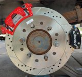
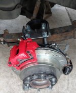
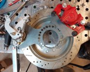
Sequoia rear disc brake conversion v1

The time had come to ditch the 94 lt1 camaro calipers and "custom" cut k1500 rotors had run their course. The braking performance wasn't great. I had never gotten around to hooking up the parking brake, they squealed badly in the rain or in reverse and were generally not where they needed to be.

I had ordered a set of sequoia rear rotors and calipers a while back so I sketched out some brackets and had them cut out of 3/8" steel at send cut send. Since they were prototypes, I added a bunch of extra mount holes so I could play with the position. I got it (mostly) right the first time and mounted them up. I got lucky in that the wilwood parking brake calipers and the sequoia caliper mounts are essentially on the same place so the two calipers were able to bolt up to the same bracket without needing to mill or weld anything.

To clear the calipers, I had to redo my leaf spring mount. Those were fabbed at home out of 3/8" plate as well. I added some "wings" to the end so they wouldn't fold over and bolted them up.

As the sequoia rotors have a larger center register than the 12 bolt does, I had some hub centering rings made up but made them taller than standard so they would index on the wheel spacer/wheel.

The setup worked well but the cable routing was a little too close too the u bolts so I adjusted the brackets in cad and send cut send cut another set out.

Sean
20230516_132254.jpg

20230604_152236.jpg

20230528_123910.jpg

20230604_174441.jpg
 
Last edited:
  • Like
Reactions: bkg

smokeysevin

Re-redoing things the third time
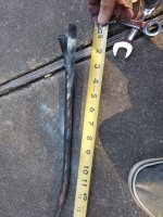
While doing some prep for the bad decisions that follow, I had to move my winch cable around. Lucky I did because I found the ground cable completely corroded internally. I have never submerged the truck, the cable was heat shrunk with adhesive lined heat shrink and there were no cuts in the cable. The terminal was however an open end barrel terminal and not of great quality. The winch ground connection was the stock harbor freight cable. I thought I had properly shielded and heat shrunk with adhesive lined heat shrink but apparently I did not which let the cable corrode internally from the ground lug on the winch up towards the battery lug.

Its been replaced with a new tinned copper marine grade wire, tinned terminals, and 2 layers of adhesive lined heat shrink. Both ends were also given a light coating of dielectric grease.

Sean

20231001_171821.jpg

20231001_171036.jpg
 
Last edited:

smokeysevin

Re-redoing things the third time
Bad decisions part 1

I had to go to Dubai for a week for work and came back with a nice per-diem bonus that I promptly spent on an impulse buy... which was a mistake?

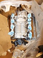
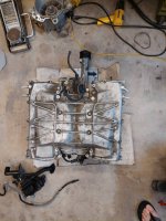
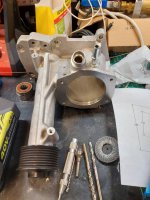
Turns out, there are some really smart people south of the equator that have figured out how to get an Eaton TVS 1900 from a 2010+ Range Rover to bolt up to a 2UZ. Now, there are several things that this truck needs/needed but a supercharger was not one of them. I put in a stupid low offer on a takeoff setup and the seller accepted. It then arrived damaged and in need of a rebuild I was able to get a partial refund for the part.

This started the fall down the rabbit hole into a hilariously expensive "cheap" supercharger install and flex fuel conversion.


Sean

20230830_141919.jpg

20230905_184053.jpg

20230830_173017.jpg

20231007_135136.jpg

20231007_143121.jpg

20231007_143137.jpg
 
Last edited:

smokeysevin

Re-redoing things the third time
Bad decisions part 2

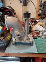
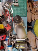
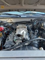
Some of y'all know, the 2uz came with 2 variants of throttle body. The early model ones (98-02) use a "cable driven" throttle that has the accelerator cable and accelerator position sensor on the throttle body itself. The later model ones use a more common style E-Throttle that is roughly square. The later model one basically bolts up to the blower while the bigger one simply does not fit.

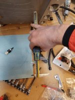
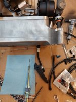
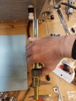
To adapt the bigger throttle body, I fabbed up an adapter elbow out of a 3.5" OD cast aluminum 90 and 2 3/8" Plates cut to the blower inlet and the throttle body pattern. I recessed the inlet elbow into the plate with a slight counter bore and will get this welded up once I can verify fitment on the truck.

Sean

20231008_153821.jpg

20231008_153826.jpg

20231008_153834.jpg

20231008_153840.jpg
 
Last edited:

smokeysevin

Re-redoing things the third time
Bad decisions 3

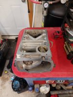
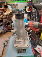
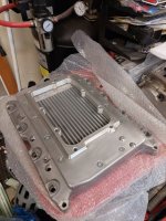
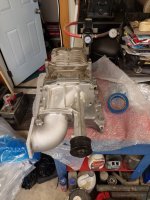
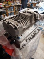
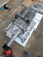
With the blower (mostly) cleaned up, I unwrapped the intercooled Elate MFG Manifold and did a quick test fit. I know the blower is not assembled, this was a dry fit. The RR blower uses a really long snout that forces the blower rearward on the manifold. This is not ideal from a performance standpoint as it partially shrouds the intercooler vs using a short snout blower. Since I will be pushing a max of 7psi (for now) I can live with the compromise since I paid $175 for the supercharger...

A couple of things I will be changing are swapping the provided cap screws for the manifold to head attachment for longer studs and nuts, installing injector adapter pieces (to be fabbed) and customizing the fuel rails.

Sean

20231009_132156.jpg

20231009_132452.jpg

20231009_132459.jpg

20231009_132506.jpg

20231009_132513.jpg
 
Last edited:

smokeysevin

Re-redoing things the third time
Bad decisions 4

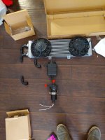
Since the supercharger manifold has an internal intercooler, I needed to add an external heat exchanger. To connect the dots, I have some -12AN 90 degree push lock fittings. The intercooler setup will also get a pump from an 03-04 Terminator Cobra and a water reservoir.

Jumping to the fuel side of the plumbing equation. I will be fabricating a new fuel pump sending unit for the tank. This will be getting a new OE Toyota Fuel level sending unit and a Bosch Motorsports fuel pump rated for E85. The stock fuel filter is getting deleted and a Snake Eater Performance 10 micron fuel filter is going just before the Continental Flex Fuel sensor. Up at the rail, the pulsation dampener and all the banjo fittings are being replaced with -06AN fuel lines. For pressure control, the stock regulator is going away in favor of a FUELAB adjustable regulator.

Sean

20231001_131622.jpg

20231001_141915.jpg

20231001_130710.jpg
 
Last edited:

smokeysevin

Re-redoing things the third time
Bad decisions 5

Fuel system part 1

I made a new fuel pump sending unit for the Bosch 450 fuel pump, new oem toyota fuel level sending unit, and the bms fuel bulkhead and got it in the tank. It makes pressure on my test loop and I should be able to get the relay setup wired later this week.

Its all 11 gauge 316ss. I only had to grind my tungsten 4 times during the assembly which is a record low for me.

The stock tundra return line is 1/4" (probably 6mm) not 5/16th like I thought.

I am planning on leaving the stock fuel pump wiring and sending unit wiring in place so it will accept a stock sending unit if I need it in an emergency. The new high power wiring and relay will go in parallel to the new connector.

Sean
7f07462c8872d914894ec3dde00edfc0.jpg
2312a31724005cb27ec8c36981e86dd9.jpg
2d000f2c421e93566ca57e8328c0cf17.jpg
0b6afcde3c520b0dd79d7c213eed4c73.jpg
2abe1f0de314c27aa01ff724589ed810.jpg
 
Last edited:

smokeysevin

Re-redoing things the third time
Bad decisions 6

Injector adapters

The elate manifold I am using is setup to run stock Denso style Toyota injectors and a lot of people have reported that running the stock injectors with a rising rate fuel pressure regulator is adequate to run these chargers and motors with ~5psi. Since I am planning to run e85 I planned to run a much bigger injector. The MAP ecu I will be using to control the additional fuel and pull timing recommends going no larger than 2X the stock injector size. The pink Toyota injectors I had on the truck are 275cc and stock for my gen 2uz are 250cc. I could have gotten some flow tested and adjusted 550cc denso injectors on ebay from cyprus of all places but I opted to get some new Bosch 550cc injectors instead.

This meant that the stock type face seals would no longer work so I picked up some 0.6875" OD aluminum rod, drilled to 0.531", then used a 13.5mm reamer to finish off the bore. I cut them to ~0.54" Lenghts and then sanded the OD down to 0.6825". I pressed the new adapters into the existing ports with some loctite green retaining compound for sealing and stiction before hitting the tops with a zero flute chamfer bit.


Sean

ea5ffac66054bc1421b1c053c5977ece.jpg

Unmodified manifold ports

3a00276bb4653fc1719e5e115c9f561a.jpg

Adapter body and bore

753169f6cdf1388d709478e642e4f429.jpg

Adapter OD after hitting it with a 36 grit belt on the belt sander

0e2700e5ce981f5d46a2c8319efe37b6.jpg

Glued and pressed in

58bab51f3d6e1f1fa41de2f671414f3f.jpg

Injector position relative to the port exit, it could be better but I don't expect issues from it

5b434a62158e621e122280e121013789.jpg

Injector position on the manifold, I could have made the adapters shorter and sunk the injector body into the port a little more but not a significant amount, the body of the injector has some little "keys" on it that foul on the body of the manifold if it sits further in.
 
Last edited:

smokeysevin

Re-redoing things the third time
Bad decisions 7

Dry fitting the manifold before pulling the water log crossover off. The elate setup requires you to modify the crossover pipe by cutting the elbow and shortening the stickout with a new 90 degree elbow. I didn't really document this very well but I will try and snap some more pictures later. Basically you weld the elbow so it follows the timing belt cover. The elate elbow is 1.4" OD at the hose location so I also picked up a 1-3/8" ID hose to connect to my radiator elbow. In these pictures I was also checking for fit of the intercooler lines and sensors as the clearances are pretty close.

Sean

20231022_143237.jpg
Temp sensors

20231022_143243.jpg
Water log fasteners are obscured by the manifold meaning you have to pull the manifold off to check/repair these connections.

20231022_143302.jpg
-12AN push lock hoses for the intercooler core

20231021_183737.jpg
Manifold body
 
Last edited:

smokeysevin

Re-redoing things the third time
Bad decisions 8

Blower assembly and dry fit 2

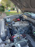
To assemble the manifold and blower you have to remove the top cap of the manifold. It is held on by tapered head M8 fasteners and sealed with a section of epdm cord. The only area I ran into an issue with the setup is the bypass valve actuator mount falls directly on the cord on one fastener and is on the pressure side of the seal on the other. To mitigate the potential for leaks I sealed the area around the one that straddles the seal with the same sealant recommended for the blower flanges and will put some on the threads for the actuator when I install it. I also put a little dab on the seam of the seal.

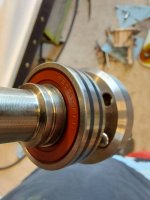
Before I installed the rebuild snout on the blower, I also drilled and tapped 2 of the stock ranger rover sensor ports for 1/8 npt plugs for additional vacuum ports and to not have to use their proprietary connectors. Unfortunately I was left with 2 ports I couldn't get out quickly so I am going to get a plug for those. At least they are on the bottom of the snout.

Also, make sure to run the boost reference line out the bottom of the manifold before you install the manifold on the motor. You don't want to do this multiple times because you forgot.

It is kind of hard to see the modified crossover pipe on the motor but it has been pressure tested and leak checked before install it on the motor with new gaskets and seals.

Sean

20231028_153841.jpg
Intercooler core and seal

20231028_153939.jpg
The red blob is the sealant

20231028_153849.jpg
Seal where the threaded actuator mount sits

20231028_155000.jpg
Assembled blower on manifold, I need to clean the rotor housing but will deal with that once everything is assembled again. Be really careful when installing the blower mounting bolts, I had to loosen the bolts and adjust the position a few times to get all of them to thread in properly and for the love of god use loctite. I also didn't take pictures of this.

20231028_172303.jpg
Dropped on for hopefully the last time, its really heavy.

20231028_172308.jpg
Money shot

20231028_172630.jpg
Everything fits under the hood
 
Last edited:

smokeysevin

Re-redoing things the third time
Bad Decisions 10

Battery mount/relay/circuit breaker holder fab

I needed somewhere to put the new relay box for the fuel pump, intercooler pump, and aux fans so I made a pseudo battery box to replace the stock toyota battery tray. It indexes in the stock locating holes and mounts my sealed relay box and the 5 push button circuit breakers that will protect the 3 new circuits plus my flex fuel sensor and wideband.

Sean

b8eb19e2f8ddb136696fdd4d055da48a.jpg
274b5a4b7050340002c81228586ab0a3.jpg
3a8b444860bcfdbe3cb685bd2b79766c.jpg
5380c6875d599c00d02bffcae351042f.jpg
011263f9c3f12eb4dd6219bb33af5c59.jpg
2e3a2706e7a551da52c39c041929830d.jpg
10fc53ffdb22bff637e518ac1b43f1ab.jpg
10b4fd275d1057c2199d158aed1e7552.jpg
a71c95ce77a3a5fe39fddb27de39d757.jpg
 

smokeysevin

Re-redoing things the third time
Bad decisions 11

IAT sensor

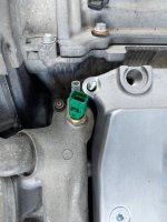
With boost and a charge cooler comes the need to watch IATs a little more closely. From the factory, the IAT sensor is in the maf tube, since the stock engine doesnt really have much that can change the air temp other than heat soaking the manifold, the difference in air temp from sensor to cylinder remains relatively consistent. With the sc and intercooler, the intercooler water temp, engine speed, boost, running time, vehicle speed all come into play to make the difference in iat different than stock.

To keep a better eye on it, I opted to install a RIFE fast acting IAT sensor in the manifold. It lives in the valley of the motor but the element itself protrudes into the air stream of the motor so it should be reasonably accurate for what is going on inside the engine, especially if it is running. Clearance is tight but it bolted up fine. The sensor uses a gm style iat plug and is 1/8npt.

Sean
2ba4ffa591cdefecefe205d2694a69bd.jpg
2c487e03f13e5ec963245f81fdb6121e.jpg
ae695cccf739732906b99d05505ab013.jpg
e7dd68f2863d24914968d929afdb9dda.jpg
 

smokeysevin

Re-redoing things the third time
Bad Decisions 12

Blower is back on and the throttle body clears. I fabbed up a throttle cable mount that I am going to redo and pressure tested the coolant system, no leaks.

I also started playing with the electrical extensions for the tps and throttle body motor and looked at intake routing.

Sean

74feb2006e0f9d56eca5c1f27cbc45a9.jpg
36227252a1d4db0f510f3eb0729bdf29.jpg
99db5ad7e6bff57c1746f4bd910ffd76.jpg
282cd3b42e78a3bc4ed9b763a2c9cad6.jpg
bc96843b83cb8df9c21a15c3116b96fb.jpg
 

Forum statistics

Threads
188,178
Messages
2,903,390
Members
229,665
Latest member
SANelson
Top