2004 Tacoma SAS

Good evening all,


I'm new here, but was inspired to share my project after starting to read through Metcalf's project here:

I started my project back in 8-24-2021. I am just going to copy and paste it all to get up to speed here with a date from the original post. Hopefully y'all enjoy it
 
Aug 24, 2021 at 8:35 PM

Hey all. I'm new to this forum and wanted to do an old fashioned build thread like I used to on other forums. So here is my long winded intro.

My names Chris. I'm from the Portland OR area and work as a fabricator/machinist. I've been an avid Toyota 4x4 enthusiast since about 2004.

This is the donor which was previously my DD/adventure rig. It's a 2004 Toyota Tacoma, 3.4 V6, 5 speed, TRD Offroad. My wife and I have had a lot of great memories in it and it was the first newer truck I've bought myself. We have a small fleet of 4x4 Toyotas, but this one has been a bit sentimental.

51401580244_e5644536cc_k.jpg


Additionally, I will be documenting this on Instagram as well for those interested. Although, this thread will obviously be far more detailed. @ pnw_trd_tacoma

51401124248_02ea781f6c_b.jpg


Unfortunately in October of last year, I was hit head on by a driver traveling in the wrong direction on a 1 way road. Insurance totaled it, and I opted to keep it. I was fortunate enough to make it unscathed, except a little bit of driving anxiety for a few months. I had been entertaining a solid axle swap for a little bit, or long travel and 35s. Since I have a mildly built 85 pickup, sometimes I wanted to do harder stuff in the Tacoma, with the comforts such as AC and horsepower haha. Well, the accident made the decision for me and here we are.

51400814666_83ce3ede05_k.jpg

51401076248_04be63c131_k.jpg

51400066432_b97a9426bd_k.jpg


Due to time and budget constraints, I feel like this project will come in phases, and unfortunately not get done super fast. Checkpoint 1 is to get it sitting on a new axle and movable before rain hits here on the PNW. Which I believe is a reasonable goal. I've slowly been gathering parts such as the donor axle, springs, frame plates, coil buckets, steering box, wheels, and roller tires for mock up(reject tires that don't balance) and more.


The goal is to fit 37s, as low as possible, and have good street manners for long road trips. Im sort of going for a Tacoma, if Toyota offered a factory solid axle. So that definitely guided my choice for suspension and axle. At some point in the process, I will have the core support and anything damaged body wise repaired. Probably when I can drive it back on a trailer again.


Here are the hypothetical specs as of now:

-80 series land cruiser front axle(elocker swap eventually) with full rebuild and manual hubs
-All stock landcruiser radius arms and suspension
-5.29 or 4.88 F/R with factory Elockers on both ends
-RCVs in front
-NW Fabworks Eco box dual case adapter with 23 spline gear driven case(stock ratio) on the back and triple sticks
-Mini truck steering box
-37" MTRs
-17x9 Method 701s


First order of business a couple months back, was to have the frame straightened. It was about 10mm out of square, due to the drivers frame rail being pushed back. Luckily, my cousin and uncle are body men so I am fortunate enough to have that resource.

51400066132_6070354209_k.jpg


After it sat for a bit out back, getting covered in pine needles and sap, it was time to drag it out and throw the 37s on to get an idea of ride height and let the creative juices get going. I am really happy with the look of the Bronze. This is the ride height I am shooting for, give or take an inch or 2.

51401075813_85b0acabbf_k.jpg

51401575654_c547e1dee1_k.jpg

51401575559_831cc519b1_k.jpg
 
Aug 24, 2021 at 8:38 PM

With the juices flowing, this past weekend I set out to repair the chunk of frame that was bent. Also, to make a cross member to both serve as a new bumper mount and support the frame when the IFS goodies are cut out.


51401796100_3dc39f0432_k.jpg


The frame rails measure about 3.125”x2.125”, .120” wall. Since that isn’t a common size, I decided to form a little replacement so I wouldn’t fight things fitting properly. I had to cut the body mount off the piece I removed and repaired it before welding it onto the new piece. After I have the IFS crap cut out and the frame plates on, I will add some more fish plating to strengthen that part where I made the splice.


51401575249_f971415ff8_k.jpg

51400813491_ec84b00ffb_k.jpg

51397186936_141edf87f2_k.jpg

51396429462_531d098518_k.jpg

51397445193_fcb74ec6a6_k.jpg


The next day I started the cross member. Its .187” wall, 2x2” square tube with ¾”, .120” wall HREW sleeves machined down, and TIG welded in. I did this for the future bumper mounts to work in double shear. I decided to keep some “legs” to wrap under the bottom of the frame for a little more strength. There is also some ⅛” plate welded between the frame and cross member to help spread the load some. I can't get anything else in there like a gusset for strength, because of clearance for the radiator.


51397921909_0ef712d553_k.jpg

51397444778_08f2f3d608_k.jpg

51397444348_3d2558d277_k.jpg

51398194890_5e8bc821e3_k.jpg


With any luck, I should hopefully have the IFS cut out by the end of this coming weekend and the axle roller under it to start designing the radius arm mounts


.
 
Aug 27, 2021 at 8:58 AM

The last 2 evenings after work have been reasonably productive. Got everything taken apart and out of the way such as brake lines, power steering, wiring. I removed the power steering pump so I didn't make mess. Took off the alternator to keep it out of harms way from the plasma cutter. Removed the struts, front driveshaft and really anything that would prevent the front end from just dropping to the ground

51405939146_864d0eb986_k.jpg

51406699579_304d86d95e_k.jpg


Before I cut anything, I took a set of trammel points and made some marks on the frame. The idea here is due to all the stress introduced to the frame from the accident, then having it pulled straight, I want to see if it moves after the IFS cross members are removed.

51406210343_8cb2858963_k.jpg

51405939051_fcf75e6f07_k.jpg


Of course it wouldn't be the PNW without some rain in the middle of a project

51406210283_714163f14d_k.jpg


And after a little plasma work, here we are! Im hoping by the end of the weekend to have the frame cleaned up, frame plates tacked on and steering box clamped to frame, coil buckets tacked in, and the axle rolled under the truck to start eye balling everything

51405190847_94d216f09f_k.jpg
 
Aug 29, 2021 at 8:55 PM


Well, while the last couple days have been fairly productive, I still wish I was a little further along. But, I'm definitely making progress.

With the suspension cut out, I wanted to check to see if the frame moved as mentioned in a previous post. When I re-scribed my lined over the pink paint stick, they both were exactly the same, and in the same scribe mark. So that was a relief.

51412064013_d090c7a4dd_k.jpg


With that out of the way, it was time to tackle cleaning the frame up....which was annoying. However, here we are.

51412730295_af57473e77_k.jpg


With that done, it was time to drag the axle out, and put it under the truck to start getting an idea of where everything will land. First issue I noticed is the lip on the wheels isn't allowing them to fully seat onto the rotor. So I took the nuts and washers off the drive flange to at least get it to sit further on and throw 2 lug nuts on for mock up purposes. I will have to bust out an aluminum carbide burr to remove that lip unfortunately.

51412506244_810af77222_k.jpg


With the wheels on, I was able to shift the axle into place, and start figuring things out. Unfortunately, I am seeing there is some stuff that is delaying things. First off, I need to get a rear sump oil pan installed before I can get things fine tuned into place and start working on other aspects of the suspension. I knew I would need a rear sump pan, but wasn't sure if not having one right now would have prevented me from getting it sitting on the suspension... clearly it is. I am also hoping I wont have to modify it.

51411003667_446c459d8f_k.jpg


I really only got to clamp some stuff in to start eye-balling where things will land. I am going to need to modify the frame plate I got from WFO to get the steering box where I need it I believe. But with it clamped in, I can now order a pitman arm.

I measured the compressed spring length on out stock FJ80 to see about what I needed to set the coil buckets to. They both weigh about the same so I figured this was a pretty good baseline. I have plenty of room for adjustment so thats good.

51411745496_afca198a90_k.jpg


I ran a string line to see about what my steering link angle would be and it is fairly reasonable at this height. I think setting up the steering link and panhard bar wont be overly complicated.

51412506019_be986c5ebf_k.jpg


This currently is the only place I am concerned when it comes to up travel. The picture makes it look like there is more room then there actually is. But the pinion flange isnt too far away from the bell housing. I can raise the truck an inch or 2, but am hoping to avoid that if possible.

51412729730_268d66c36d_k.jpg


This is currently the biggest hurdle for my first checkpoint. I was hoping that I could avoid messing with the trans cross member until after the truck was sitting on its own suspension. However, that's not my reality. Ideally, I would like to tuck the radius arm up a little more. In this photo, its set at the proper caster for a stock fj80. I am fairly confident I can tuck it up more with a little work such as offset bushings in the front, maybe a little modification to the mount.

51411745366_d69a9aa73c_k.jpg


Lastly, here are some photos of how far forward the axle is pushed. I am an idiot and forgot to measure it before cutting crap out. But its a couple inches. I can probably go back about an inch, which I may do. I am hoping to not have to butcher the front sheet metal for full stuff and turn in front.

51411003422_7297fbaf7e_k.jpg

51412505289_20cfc48187_k.jpg


Thats all for this weekend. Pretty close to my goal. Now I need to order a pitman arm, and oil pan kit before I can make any big dents in the project
 
Sep 6, 2021 at 9:27 PM

Well, as per standard operating procedure, I am not as far along as I would like to be at this point in time. This weekend ended up not being as productive as I wish it were, but still making progress.


This week I was able to collect some parts. I ordered and received a nice steering arm from Sky

Went to my local Toyota dealership for all the parts to convert to a rear sump oil pan

51431171752_f5464f4112_k.jpg

51432898490_c87864f2b0_k.jpg


This is the part I am most excited about scoring. I have been looking for a high pinion elocker for quite some time, and after enough pestering of a buddy at a local shop, I finally got my hands on one for a really nice price. If I can't get my hands onto an empty 80 series front elocker housing, I will do the retro-fit on it. I've done a few but am hoping for factory goodness.

51432674974_166f65c554_k.jpg


Next was to tackle something I hadn't been looking forward to. The radius arms landed right where the factory cross member mounts were. Ideally, I didn't want to touch the trans, so I could build my new cross member around everything sitting in the factory location. However, something had to move. So I scabbed together some spare steel, and welded in(don't mind the ******** welds) some temporary supports. Nothing seemed to move more than 1/16" so I will take it as a win.

51431171237_4ce3491160_k.jpg

51432170323_931b075676_k.jpg


Once that was welded in, I cut out the stuff in the way and ground the chassis clean. It was actually rather time consuming, and a part of the project I wasn't fond of. However, we got it.

51432897740_dce75244e1_k.jpg

51432674429_3243d58b00_k.jpg


With all that clear, and the radius arms bolted to the axle and tight, it was time to stare at the truck for a while and take a bunch of measurements. I decided the center of the mounting hole being 3" below the bottom of the frame was about all the more I could tuck it up. With the way the radius arms cross over the frame, I didn't think they would clear on full articulation. Much higher, and they appear to crash into the frame the best I could measure.

Since radius arm mounts are the next thing I need to have made and fit up, I wasn't able to spare the time to have my old shop laser cut the parts for me. It was a minimum of a week out, so I had to tackle the time consuming task of making stuff myself.

First thing was to get a precision template utilizing my expert CADboard skills. A combo of porta-band and plasma action and I had the pieces roughed out. Since some of these parts are critical in dimension, used my mill to make everything that was important, perfect. This allows me to set the side to side spacing perfect so there is only about .020" extra width for the radius arm sleeves. I also made slotted holes for fine tuning of the front axle. The idea here is to measure a bazillion times and tighten it up with some large washers on the outside edges. Once I am ready to drive it, I will take it to a friends shop for an alignment then when its perfect, I will stitch weld the washers on to keep it set for good. The slotted holes turned out a bit crude for my taste, but they should be covered by the large washers once its permanently set.

51432170018_497e60267a_k.jpg


After I TIG tacked everything together, I did a quick test fit. The frame has a taper in the location I am mounting these, so I wanted to make sure I got everything dead on before welding anything together. I did't want anything having to be forced into position to mount.

51432169538_83bd566e10_k.jpg

51432673864_a7229d9c36_k.jpg


Once it was in there, I decided the little gussets on top need to go away, and larger ones on need to be made and put on the outside edges. There will be a large cap plate as well that will add strength, and keep crap from building up on top of the mounts. For now, these little gussets served well as proof of concept and helped me verify my measurements were correct for the angle of the frame. Hopefully tomorrow evening I will be able to get in 1 last test fit with the new gussets/cap, and the mounts heavy tacked into place.

51432673674_ed5d3bf276_k.jpg
 
Sep 12, 2021 at 10:13 PM

More progress this week/weekend. Although, like the last few posts, not as much as I am hoping.


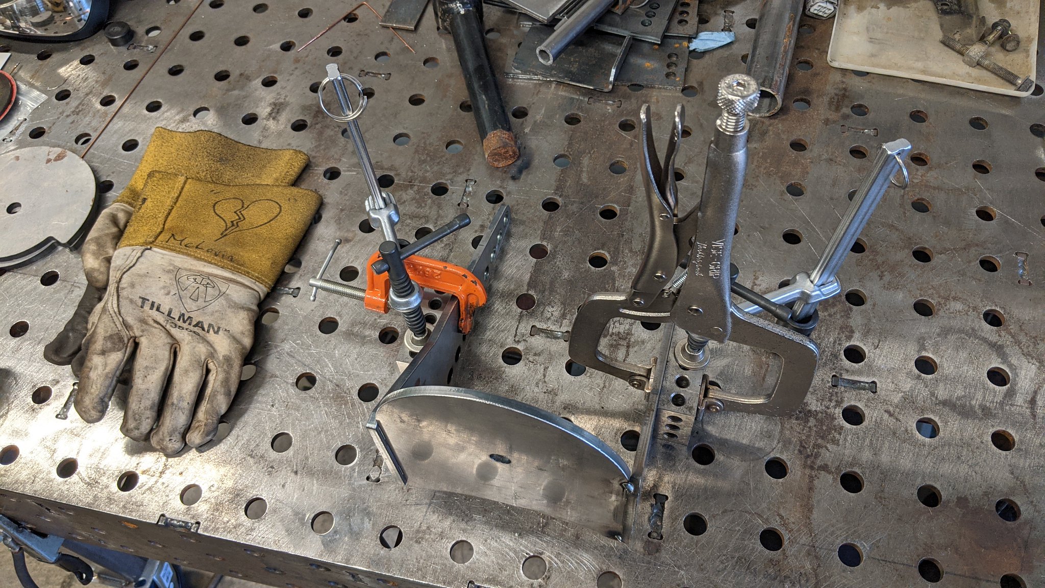
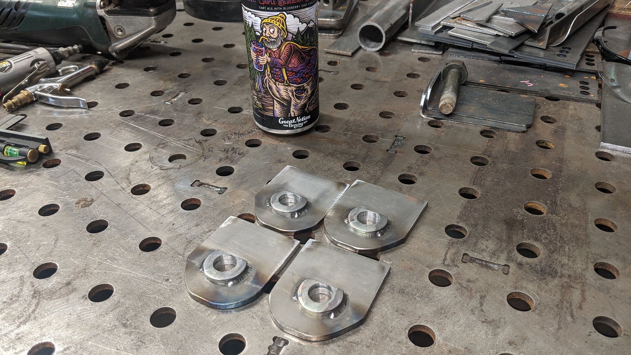
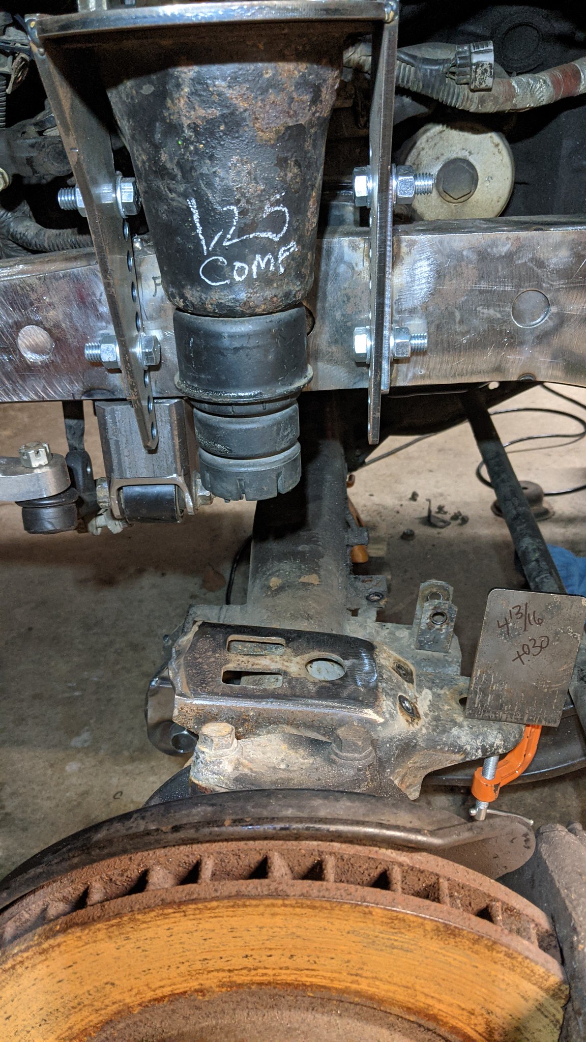
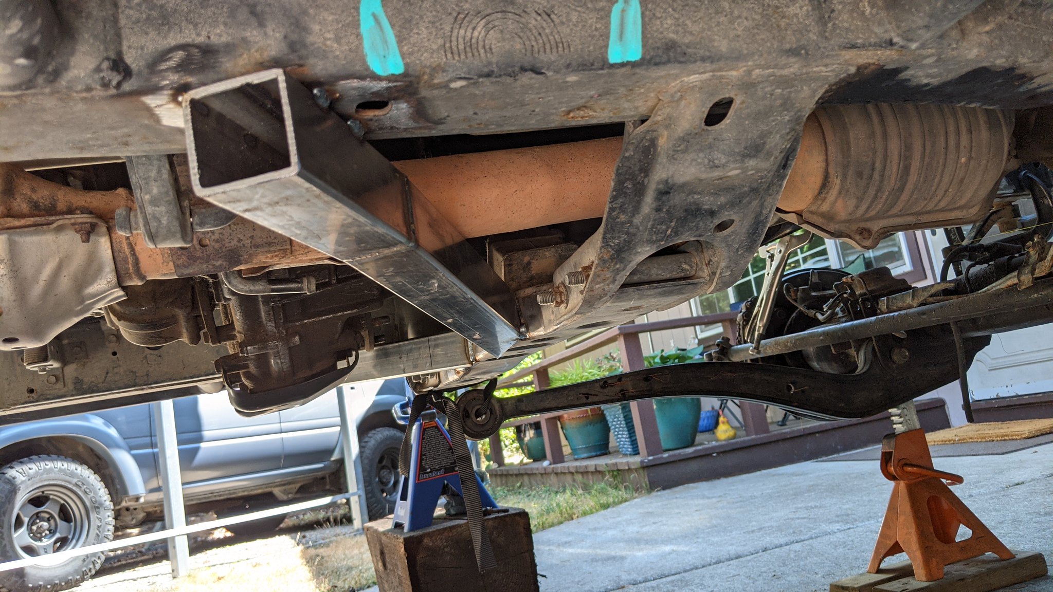
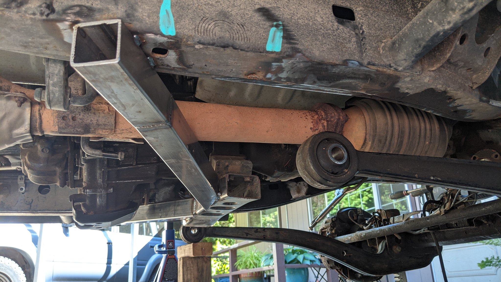
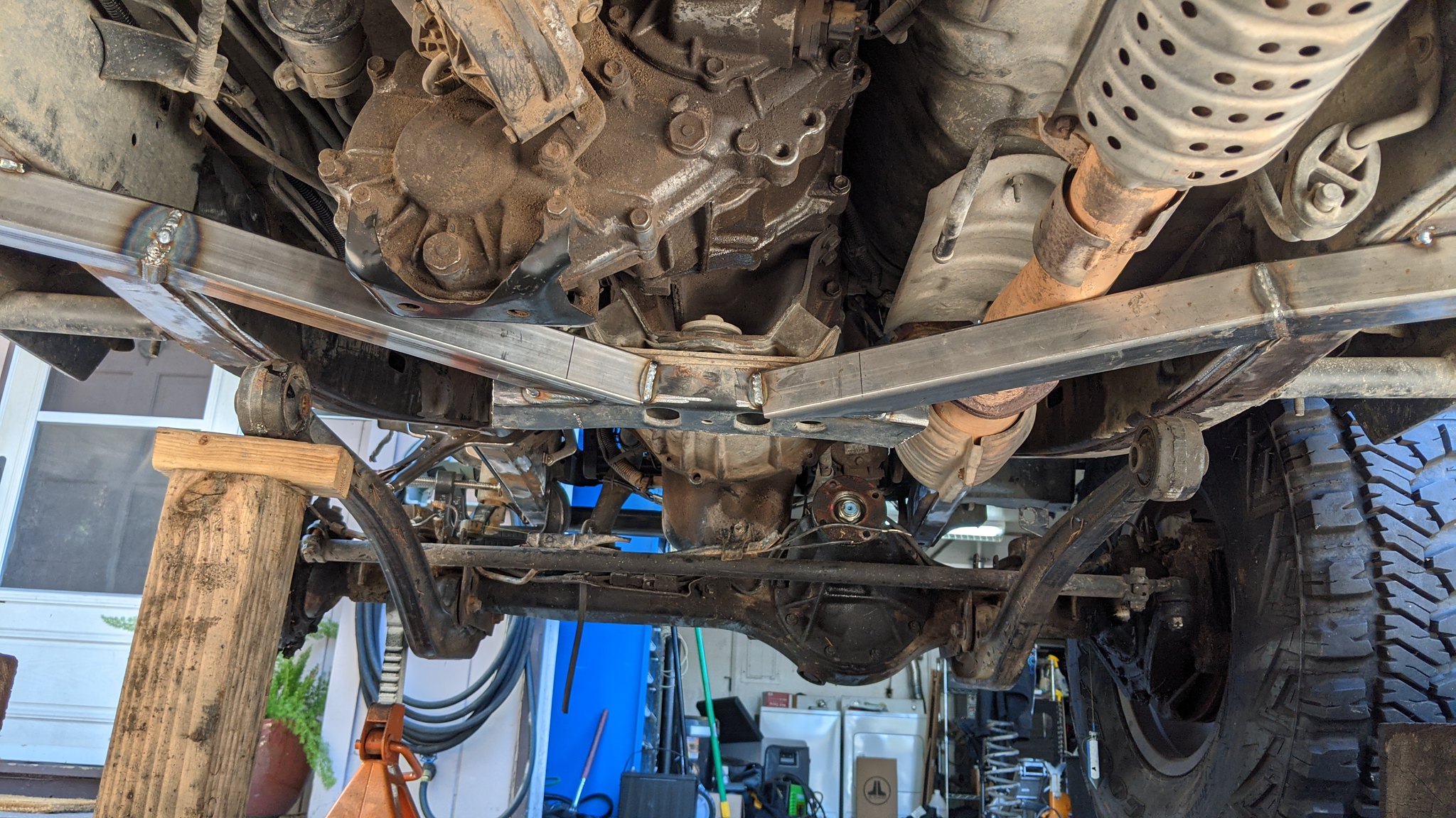
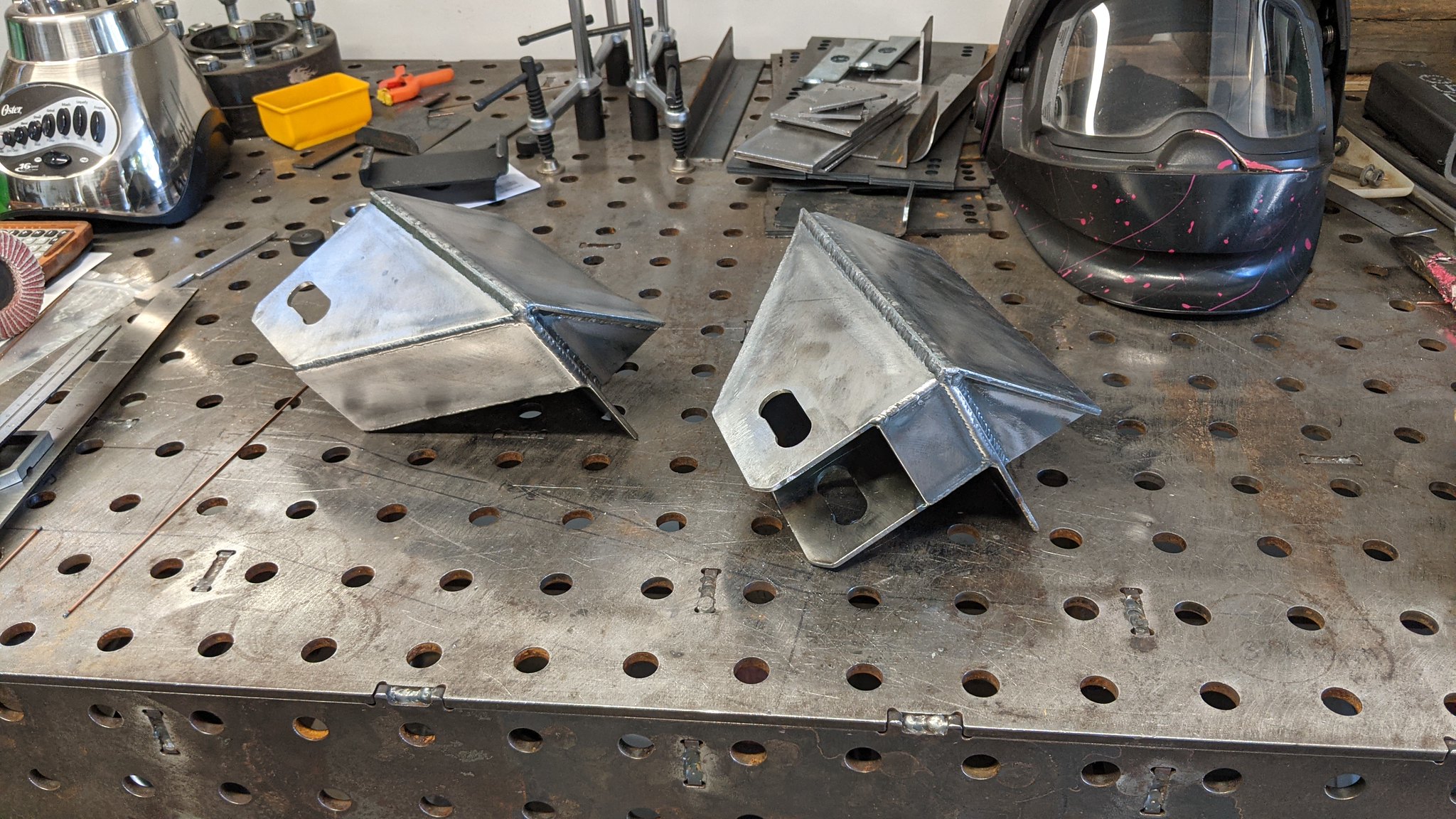
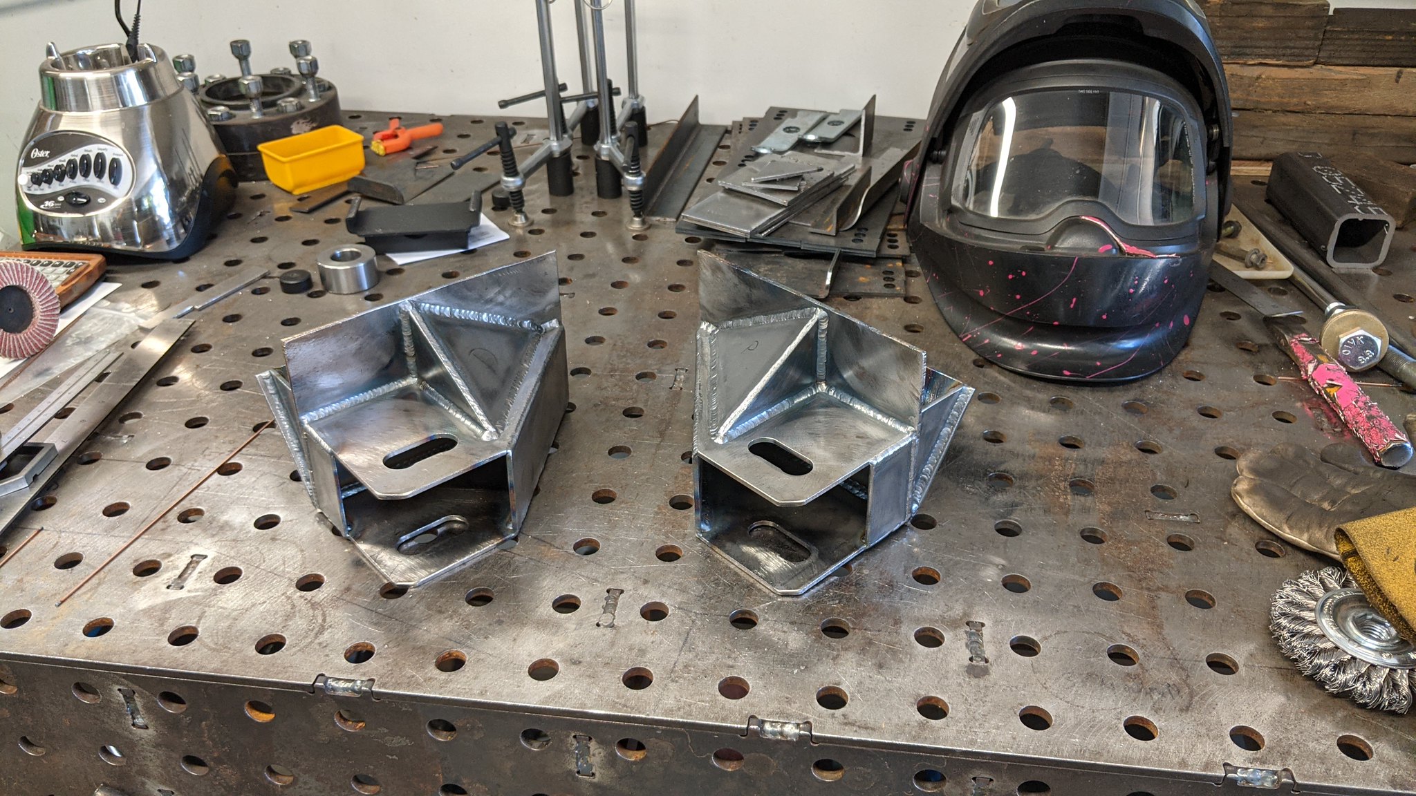
After the the test fit for the radius arms was complete, I made a couple adjustments for a little more strength and TIG welded everything together. I am not the worlds best TIG welder, so its certainly no weld porn.


51461690824_b546539563_k.jpg

51460197832_08a616e43c_k.jpg


With them all welded up, I got them tacked in really firmly so I can eventually put some weight on the truck and see if everything landed where I wanted.

51460197522_2b32522578_k.jpg

51461910725_5e5af4b49c_k.jpg


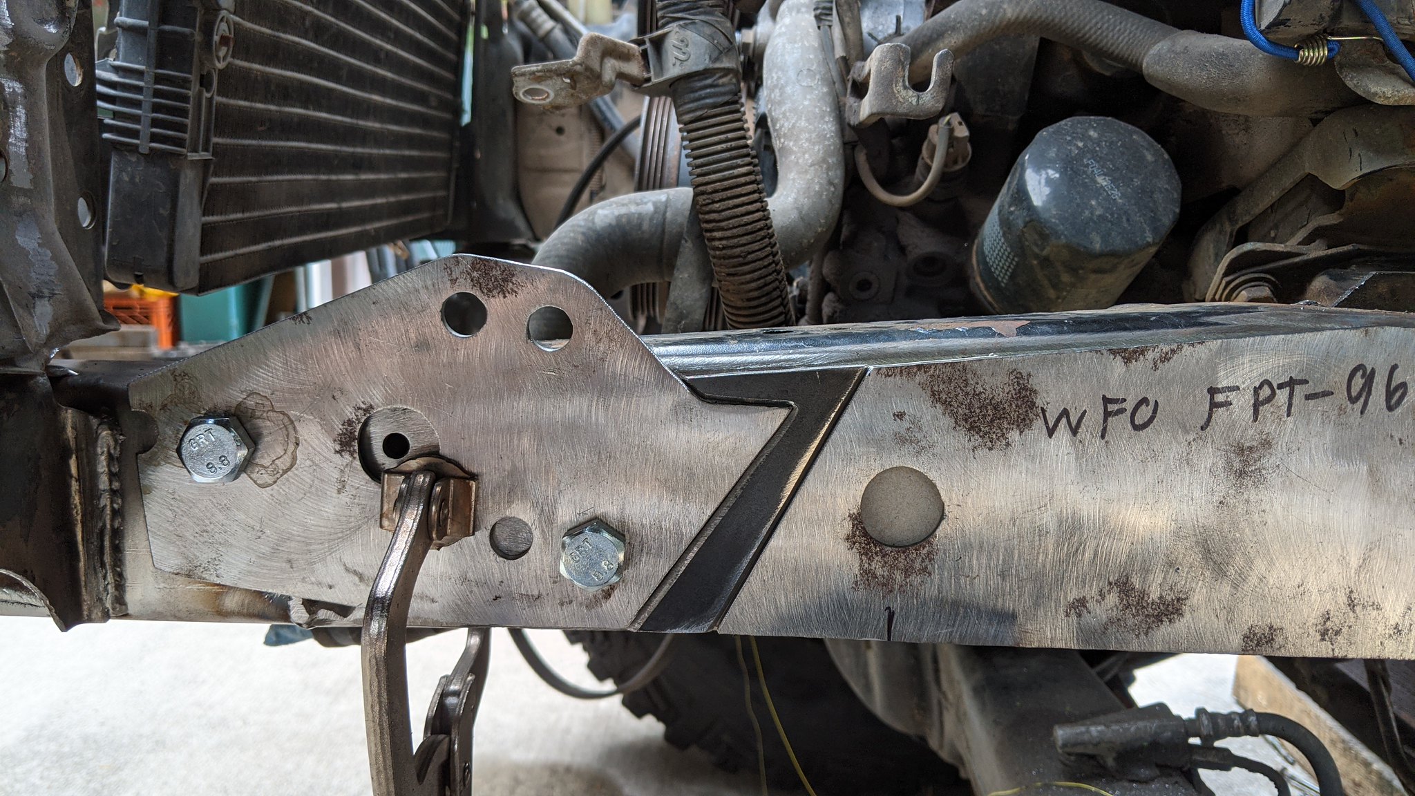
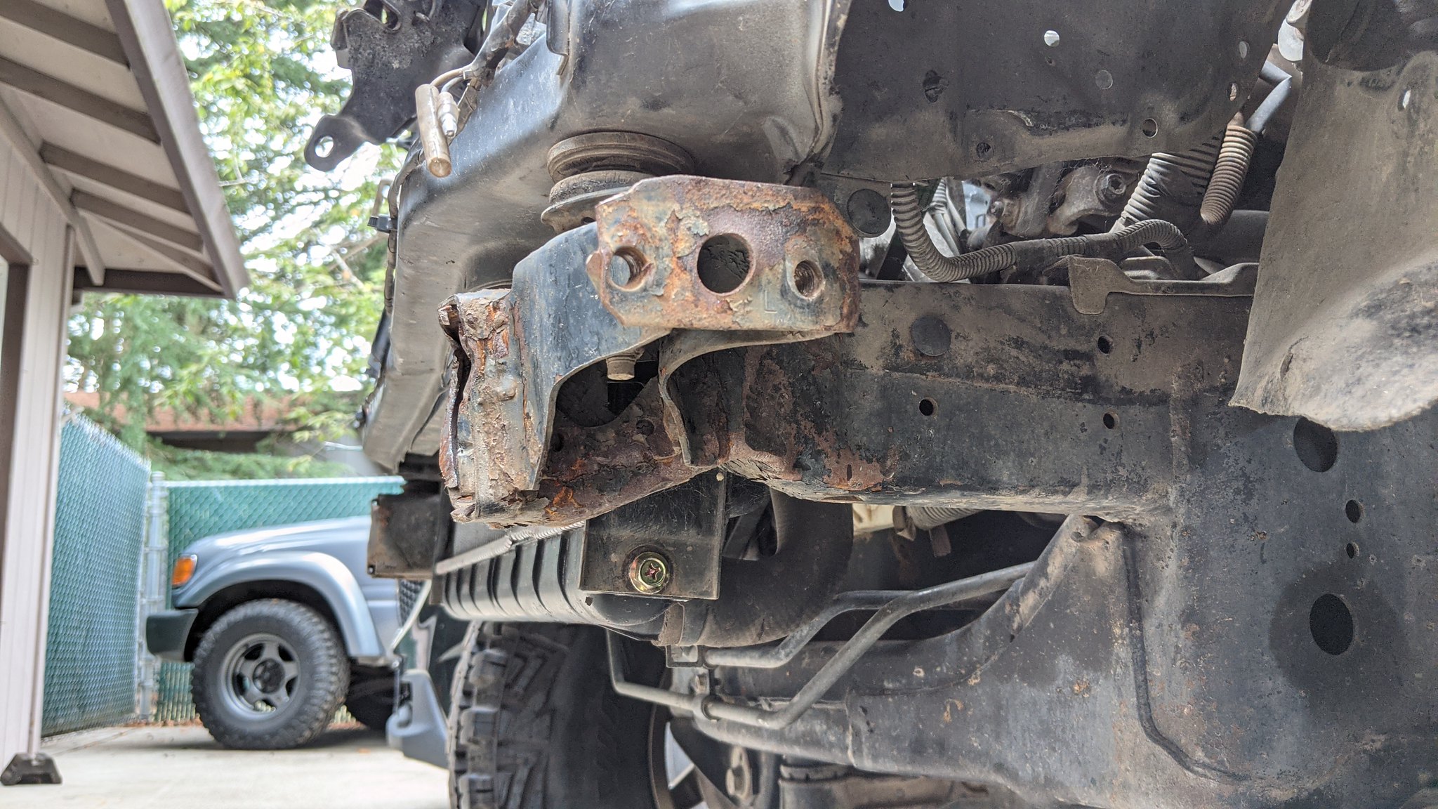
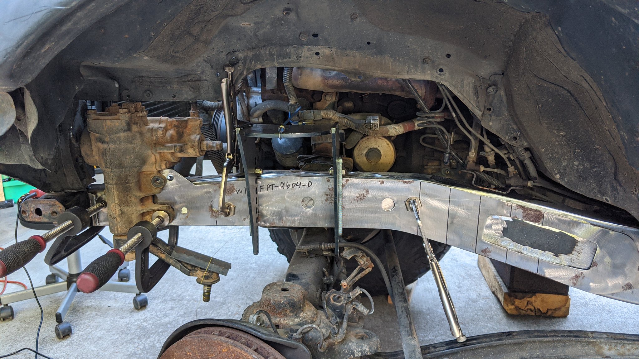
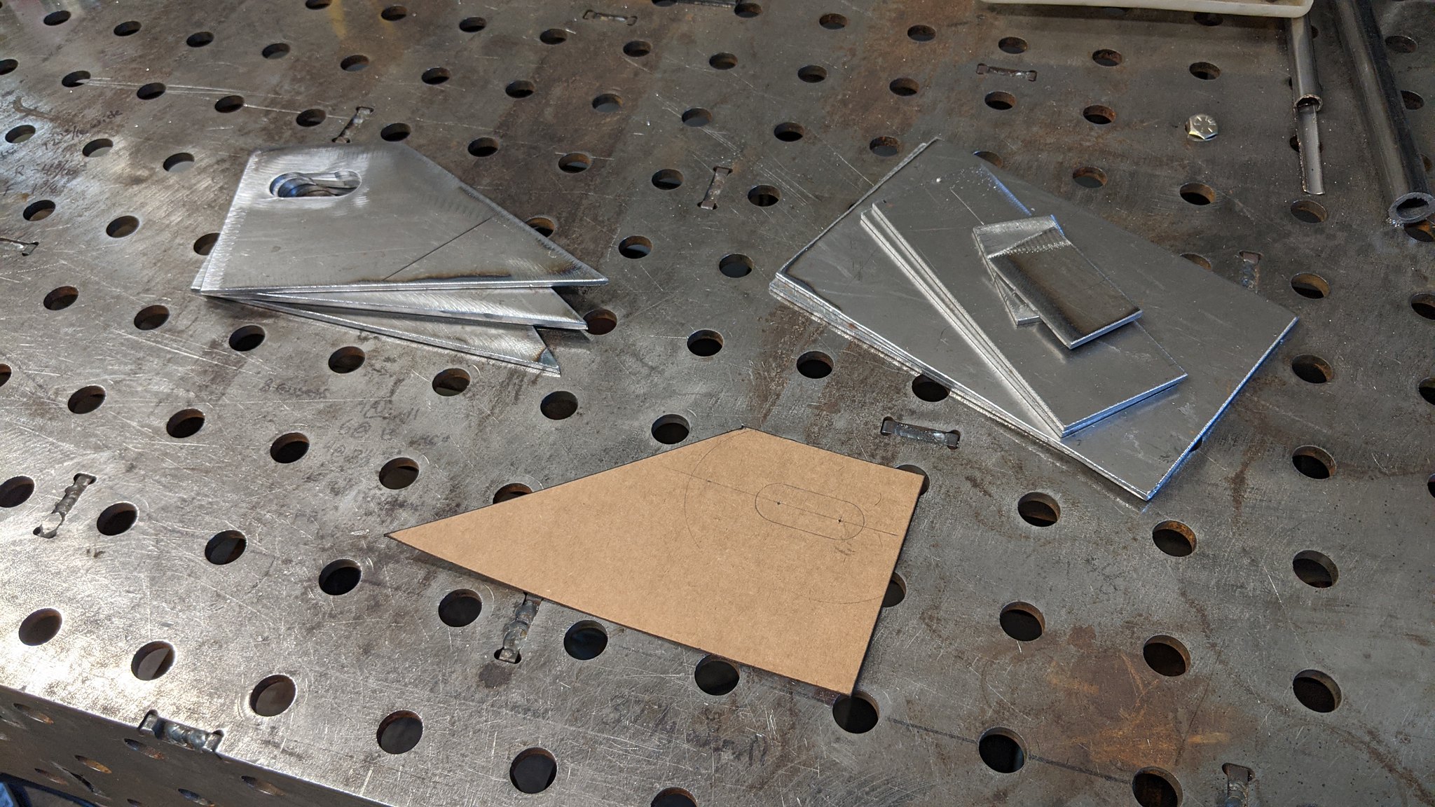
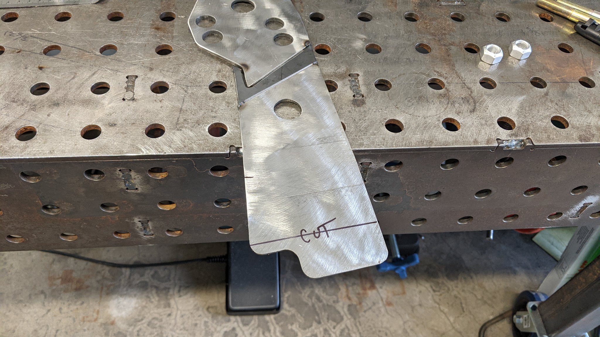
Next order of business was to get the steering box mounted. This proved to be a very time consuming process. Since I knew I planned on modifying the chassis plates to set the box in a better spot for my truck, I needed to set the steering before getting the plates tacked on and working on anything else such as coils mounts and panhard mount. The box got clamped to the bare frame(not pictured) and I and I marked the holes, then drilled the frame for the sleeves. Once the chassis was drilled, I cut the chassis plate and clamped everything on, so I could make a template for a filler piece.

51461205543_317f298a73_k.jpg


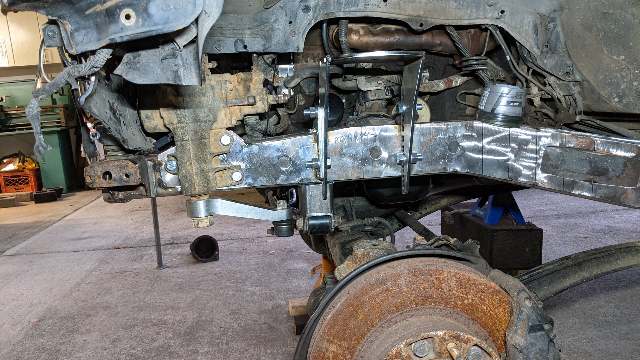
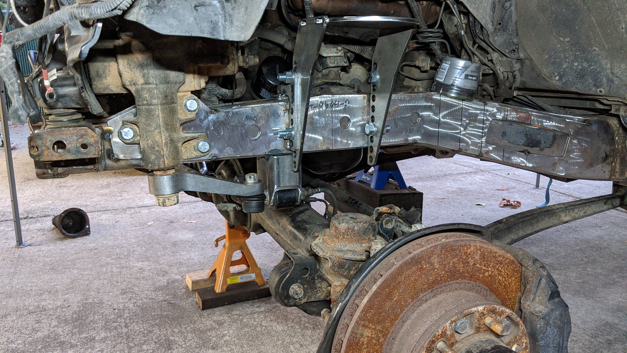
With the holes drilled, the plate cut, and template made, I cut 2 filler pieces. I clamped both sides together before cutting anything, so I could duplicate the filler plate. Once the filler was made, I TIG welded everything together and ground it flush so you cant even tell it was cut. You'll see that in later photos.


51460961996_782a352716_k.jpg


With the outside plate finished, It was time to move onto getting the sleeves for the steering box properly installed. This is where I have some criticisms of the kit I purchased. I got the kit from WFO because it looked closest to what I was doing. I knew there was a chance I would have to modify it, but that isn't where my gripe was. First of all, I would like to start by saying that I am probably unnecessarily OCD about some details. First of which, the hardware included is 1/2" fine thread grade 8 fasteners. Quality stuff, but I don't like mixing metric and standard hardware. It seems lazy and cheap in my opinion. Grant it, the easy solution is to run a 1/2" drill through the 3 holes on the steering box and move on with my life.... but that's not how I roll.

Second, and this one is truly just lame to me... is the zinc coated spacer sleeves. Anyone who welds/fabricates for a living knows that stuff needs to be removed for a good weld. More importantly, the fumes aren't good for you. A simple solution would be 3/4", .120 wall DOM or HREW cut to length. That's essentially what these sleeves are. Initially I was going to machine some proper sleeves, but said screw it and ground the zinc off in the places I needed to weld.

So this morning before getting started, I went to my local hardware store to grab some generic 12mm fasteners so I could fit everything up for now. Later I will source better fasteners after everything is blown apart for final paint and re assembly.

Rant off:

51461909920_3587e35872_k.jpg


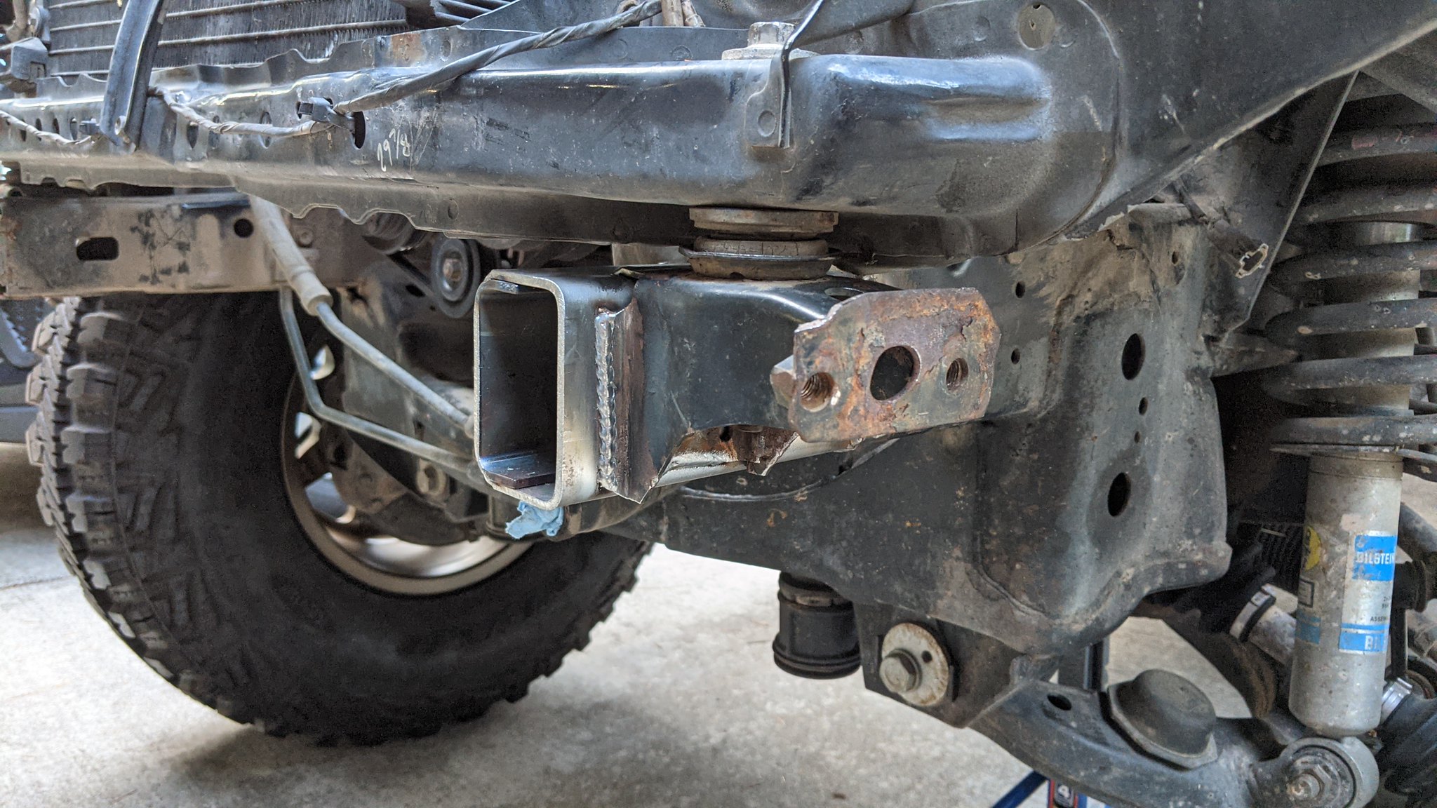
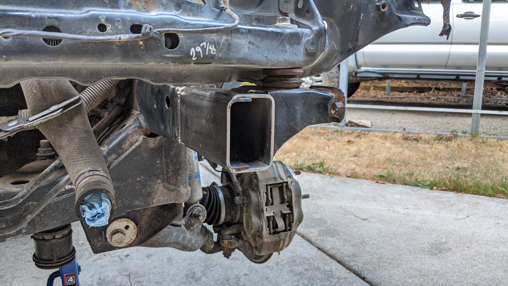
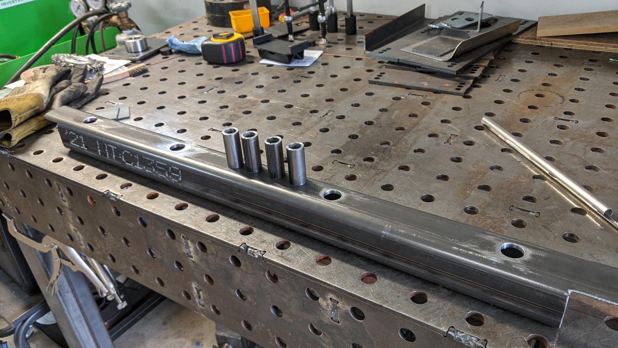
It was time to move onto getting the sleeves tacked on, square to the outside of the frame. It was more simple to clamp everything together using only the outside plate, and tighten the bolts to ensure the sleeves were sitting square on the chassis plates. After this, I took the chassis plate off, and welded the outside edge to the bare frame(I pre beveled everything to allow for weld), then ground it flush for the plates to sit nicely on the chassis.


51460878189_879ed65f24_k.jpg


With the sleeves set, it was time to move onto the inside plate. First thing I noticed is there needed to be a bend closer to the engine mount. I don't like just clamping it out. That introduces stress to the frame and that's unnecessary.

51461205098_dcd201cdea_k.jpg


So I put a little bend in it so it fits better. I also cut a little of the end, because it was interfering with the engine mount. It would have actually been worse if I didn't modify it already. So I suppose those are 2 more criticisms for the WFO kit.

51460153951_5a7af8a0e4_k.jpg

51460881749_464ed008af_k.jpg


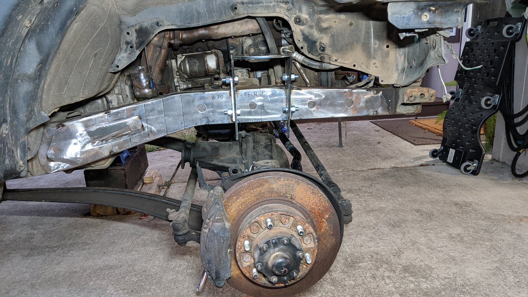
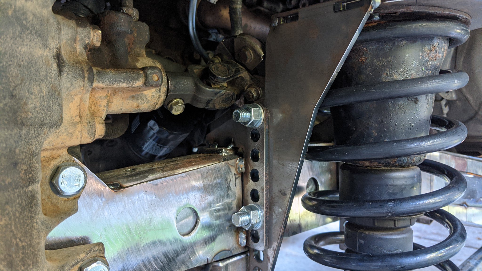
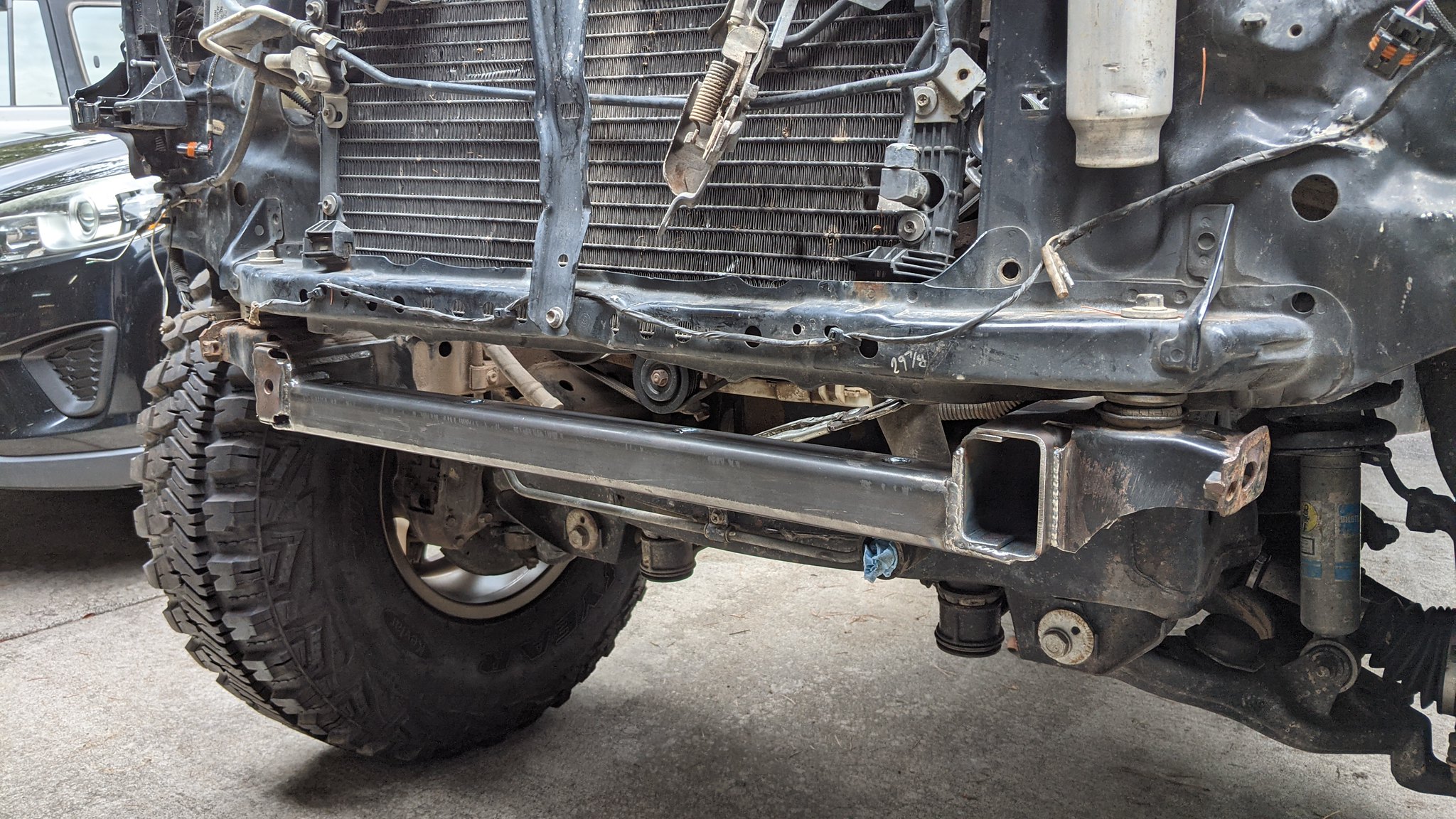
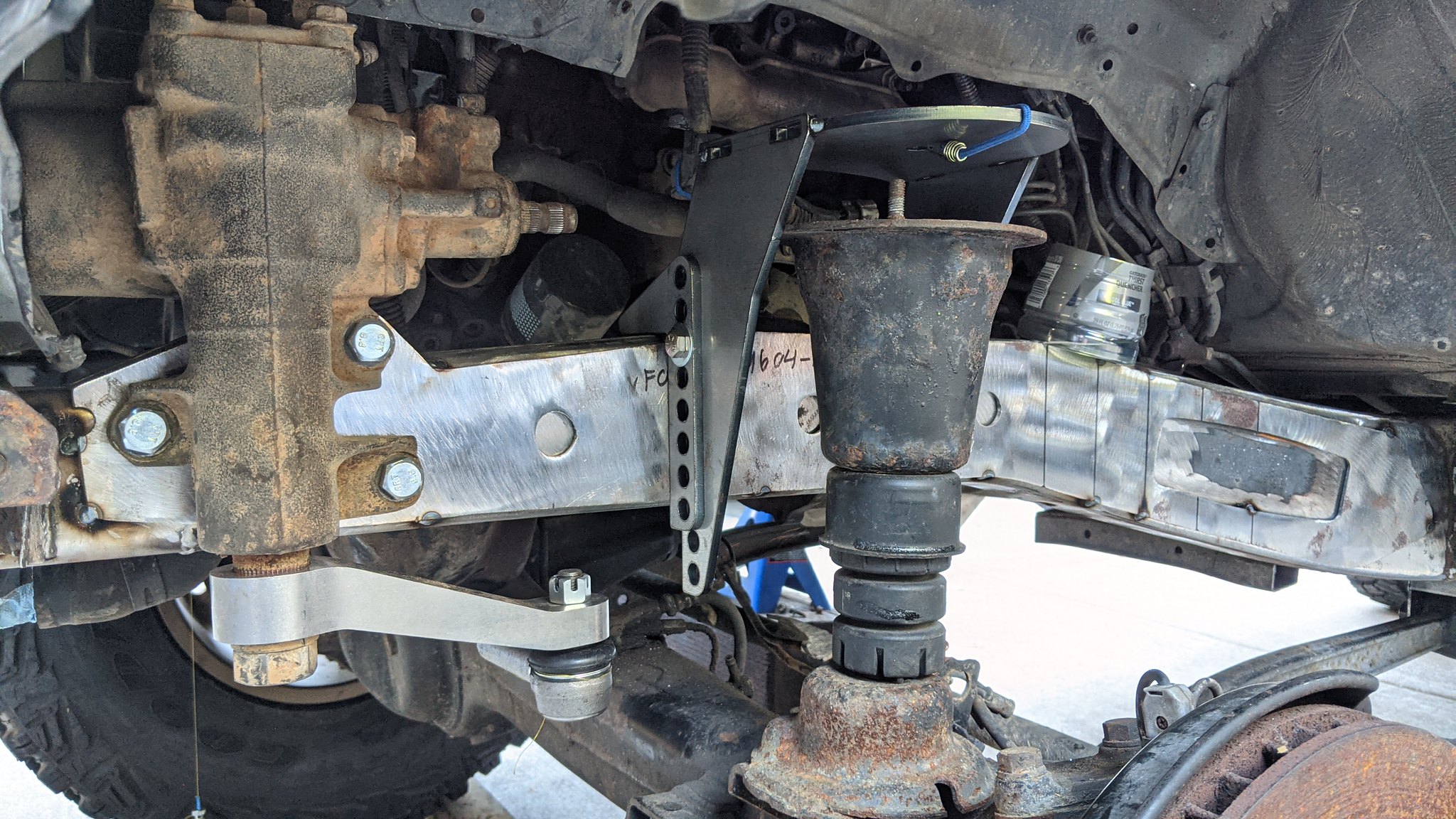
With the extra bend, and the plate all welded up and ground flat, I had it fitting nicely. I did end up adding another small bend at the front of the chassis because of the small gap due to the replacement chunk of frame I made. So there is a small bend in the plate at the bottom of the photo and now that end sits nice and flat against the chassis.

51460874594_eae8b231c9_k.jpg


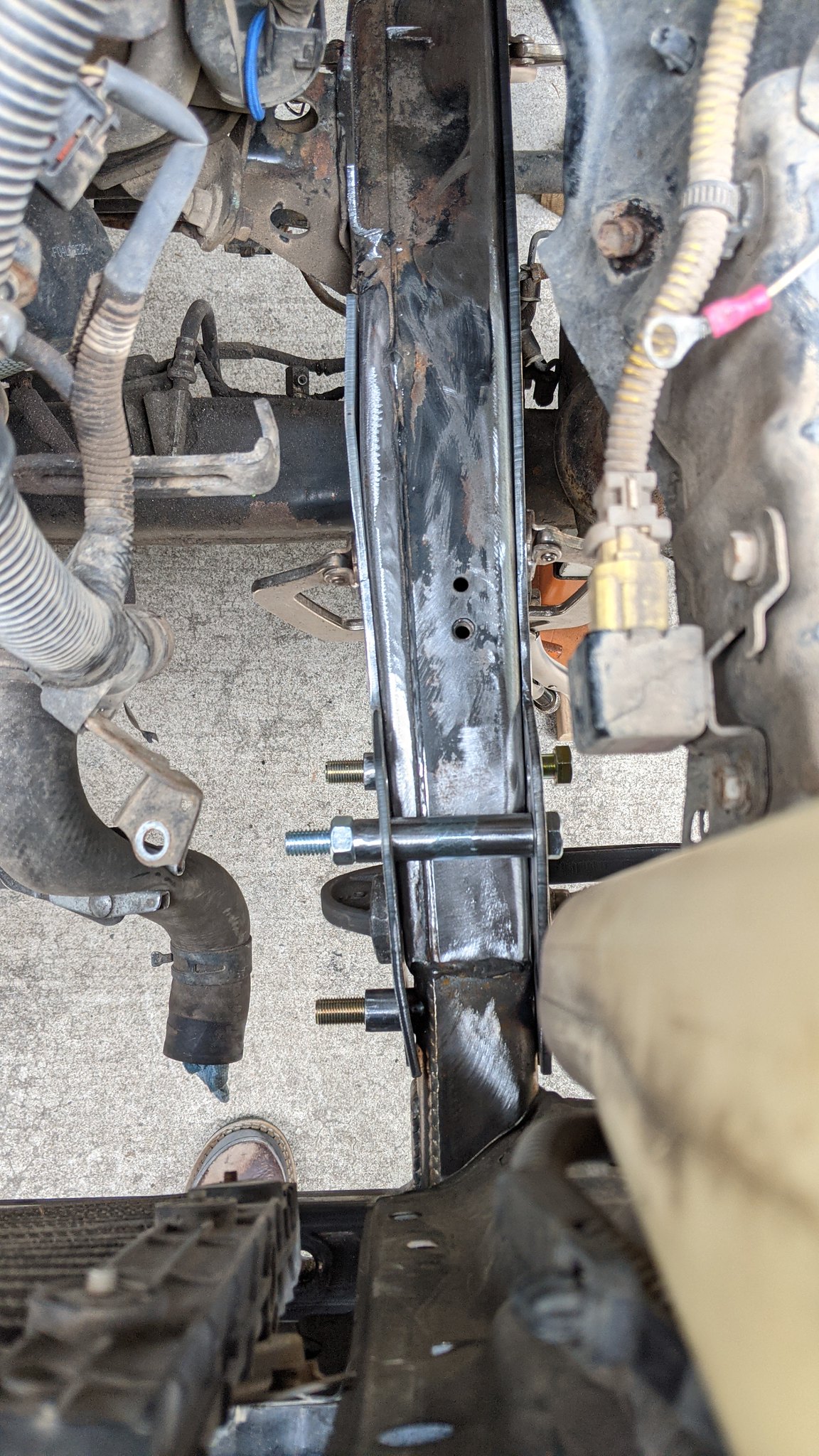
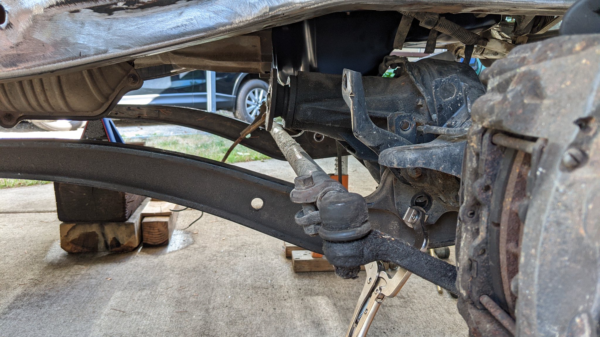
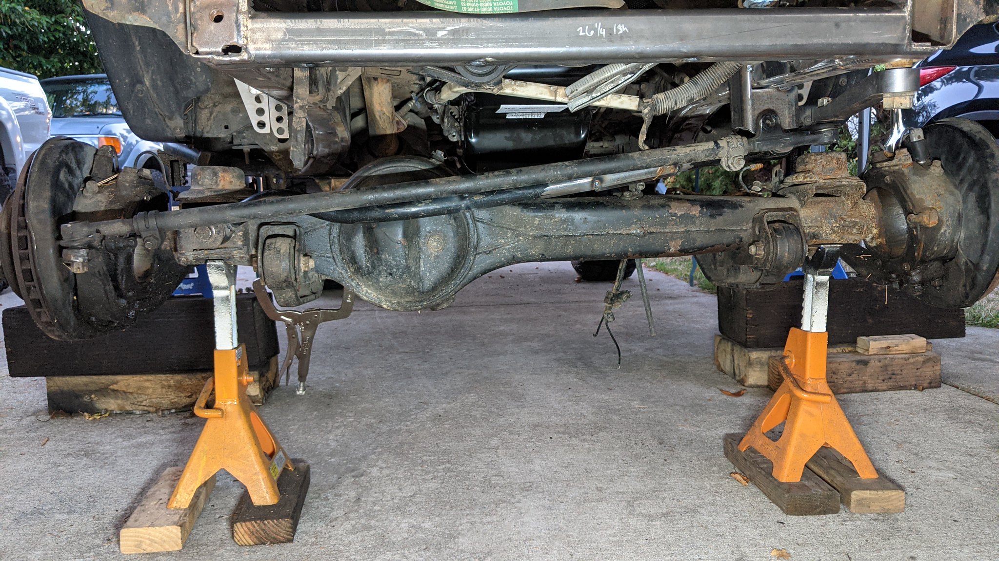
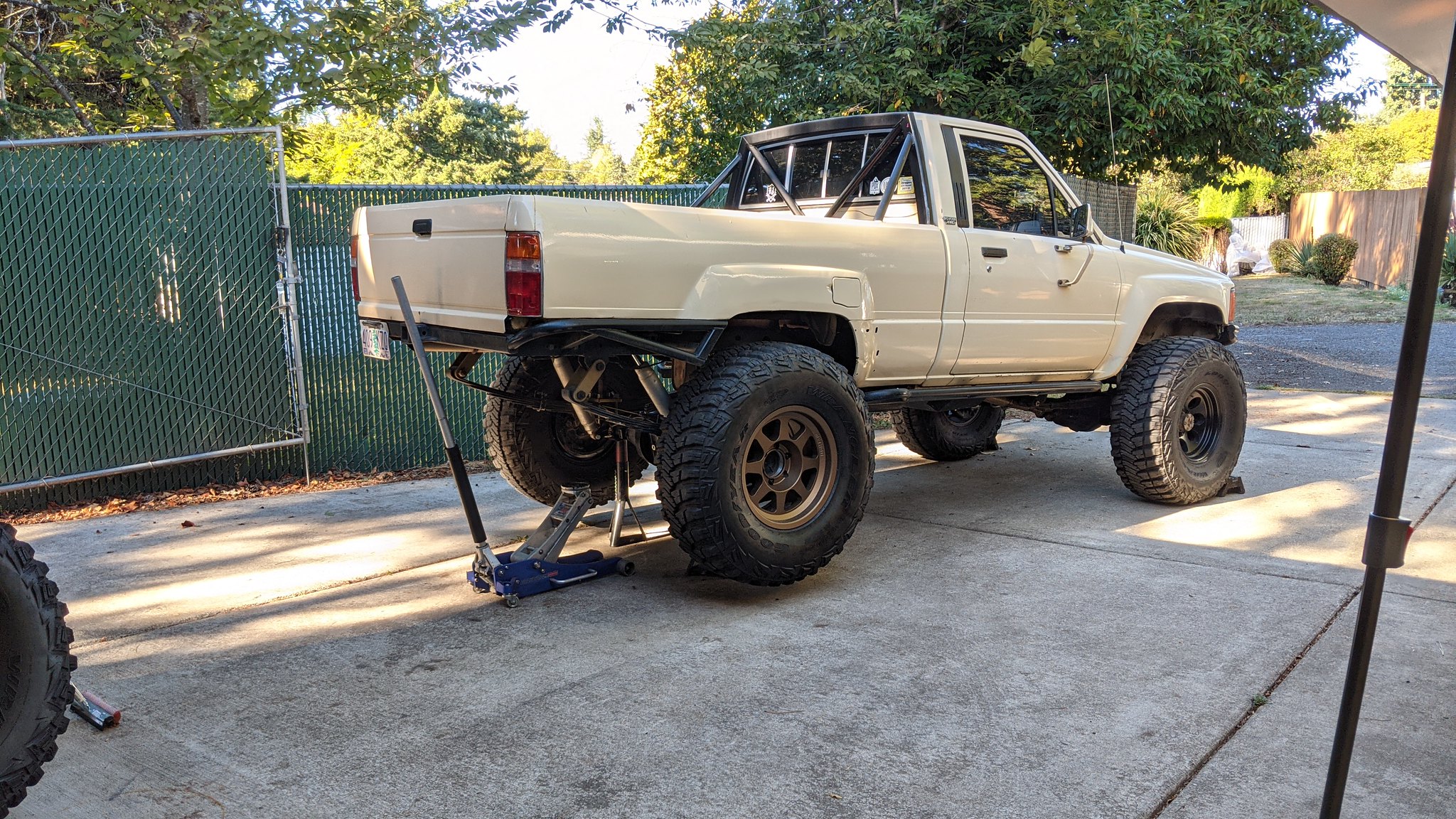
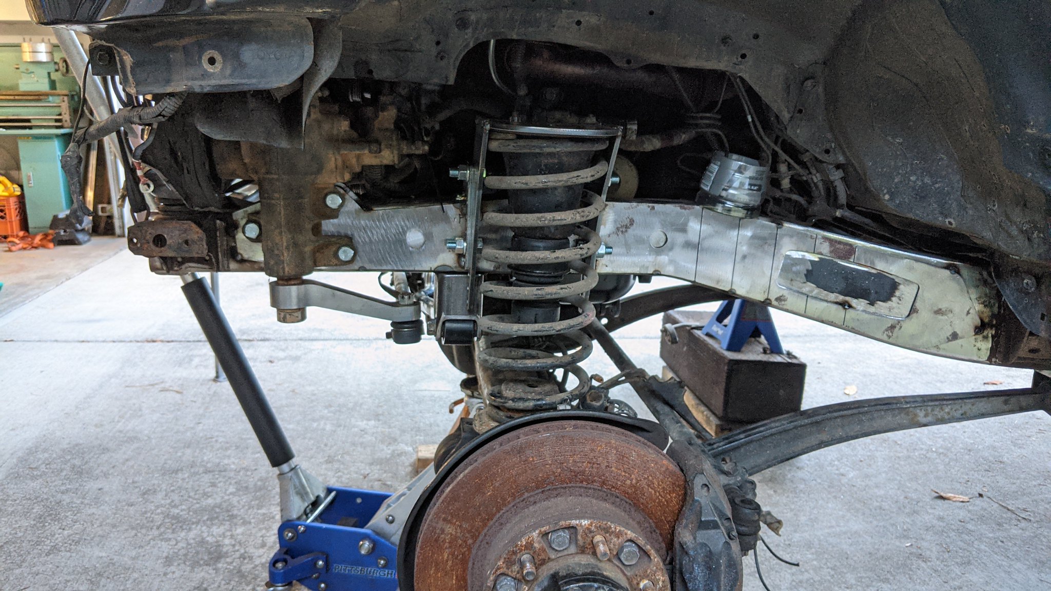
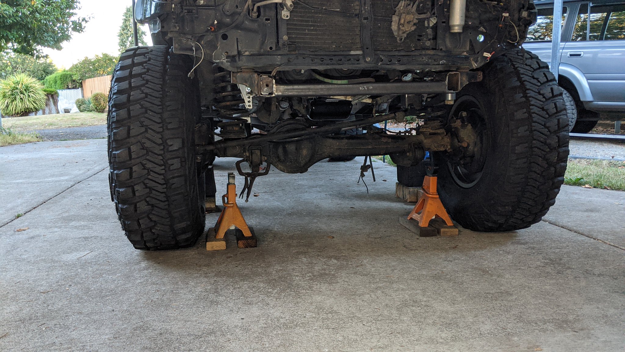
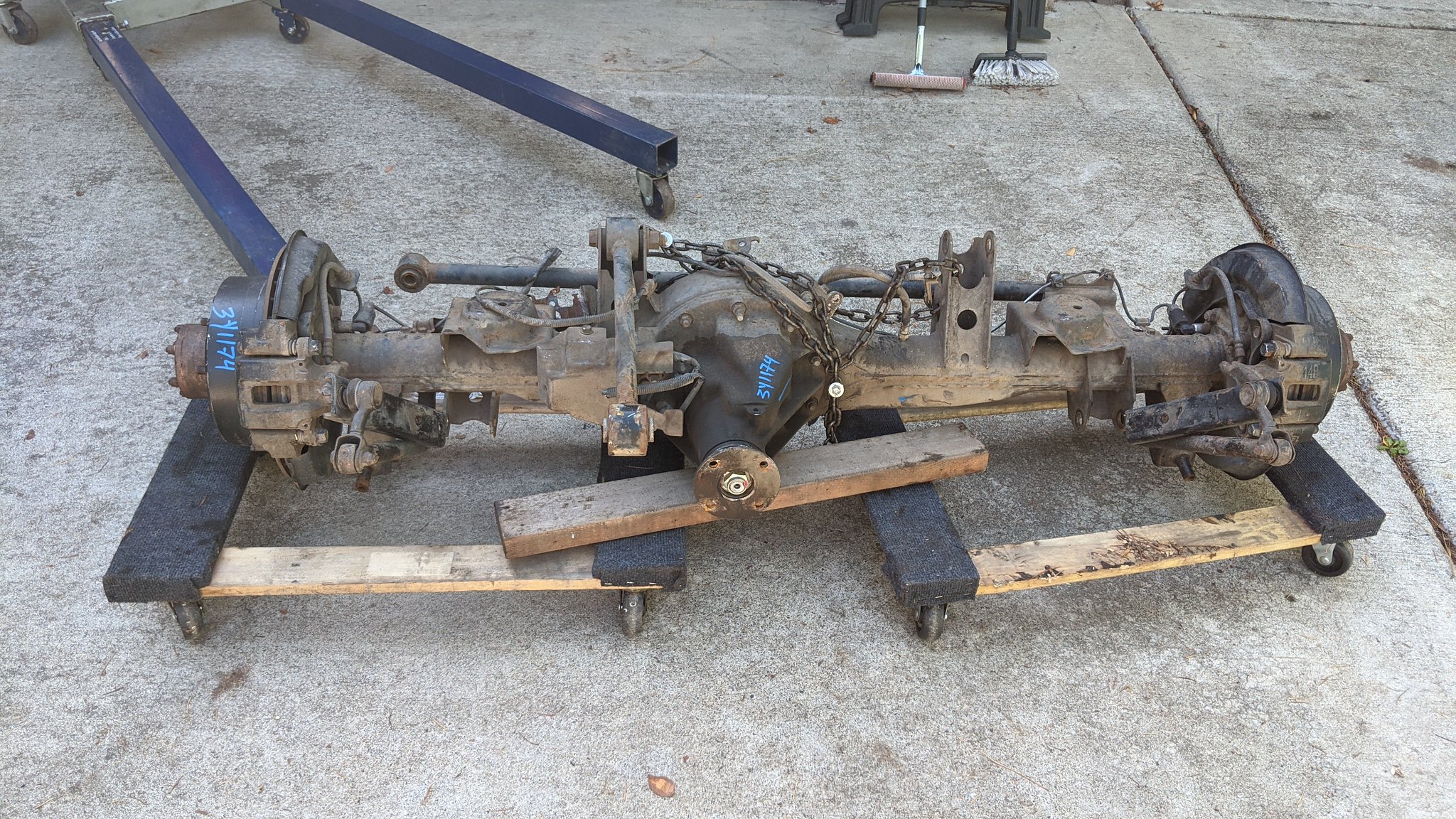
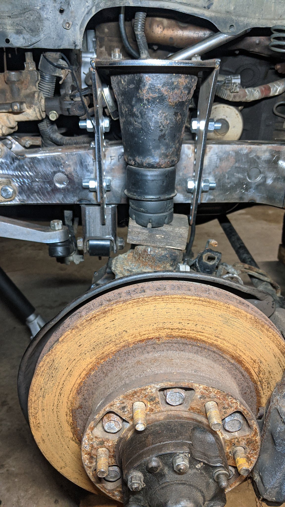
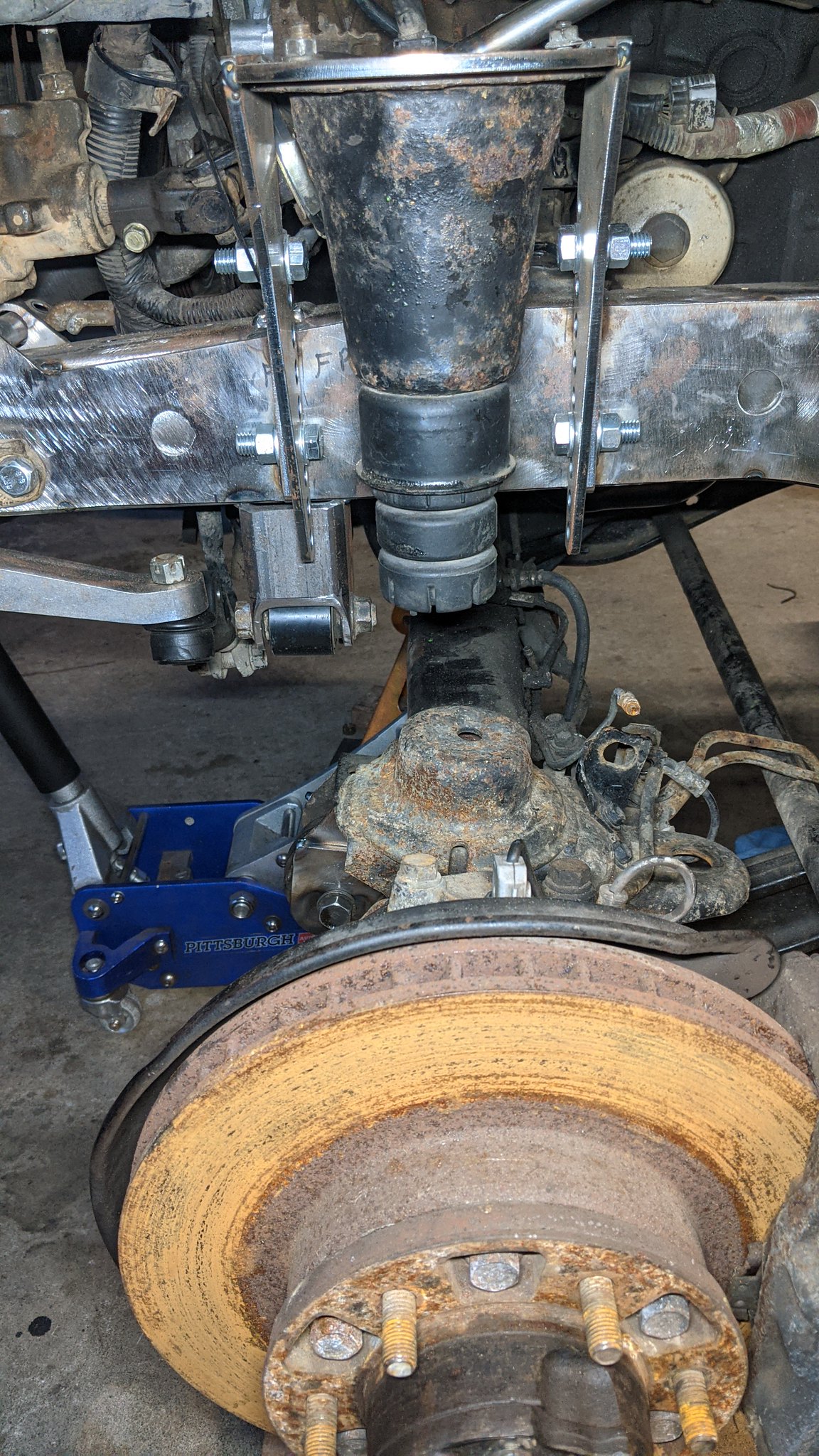
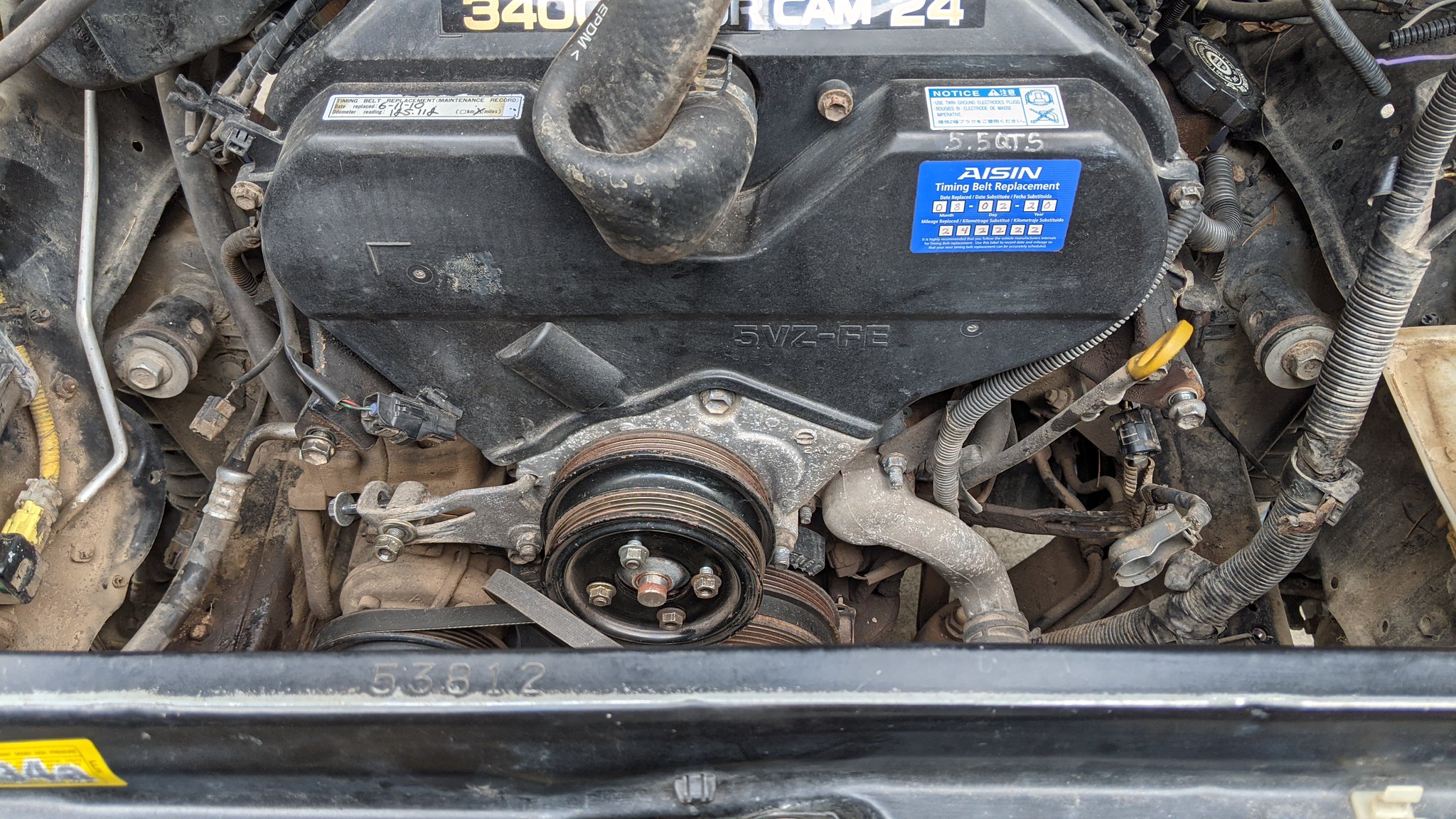
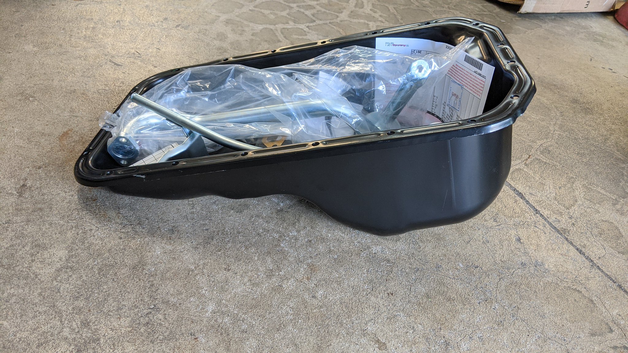
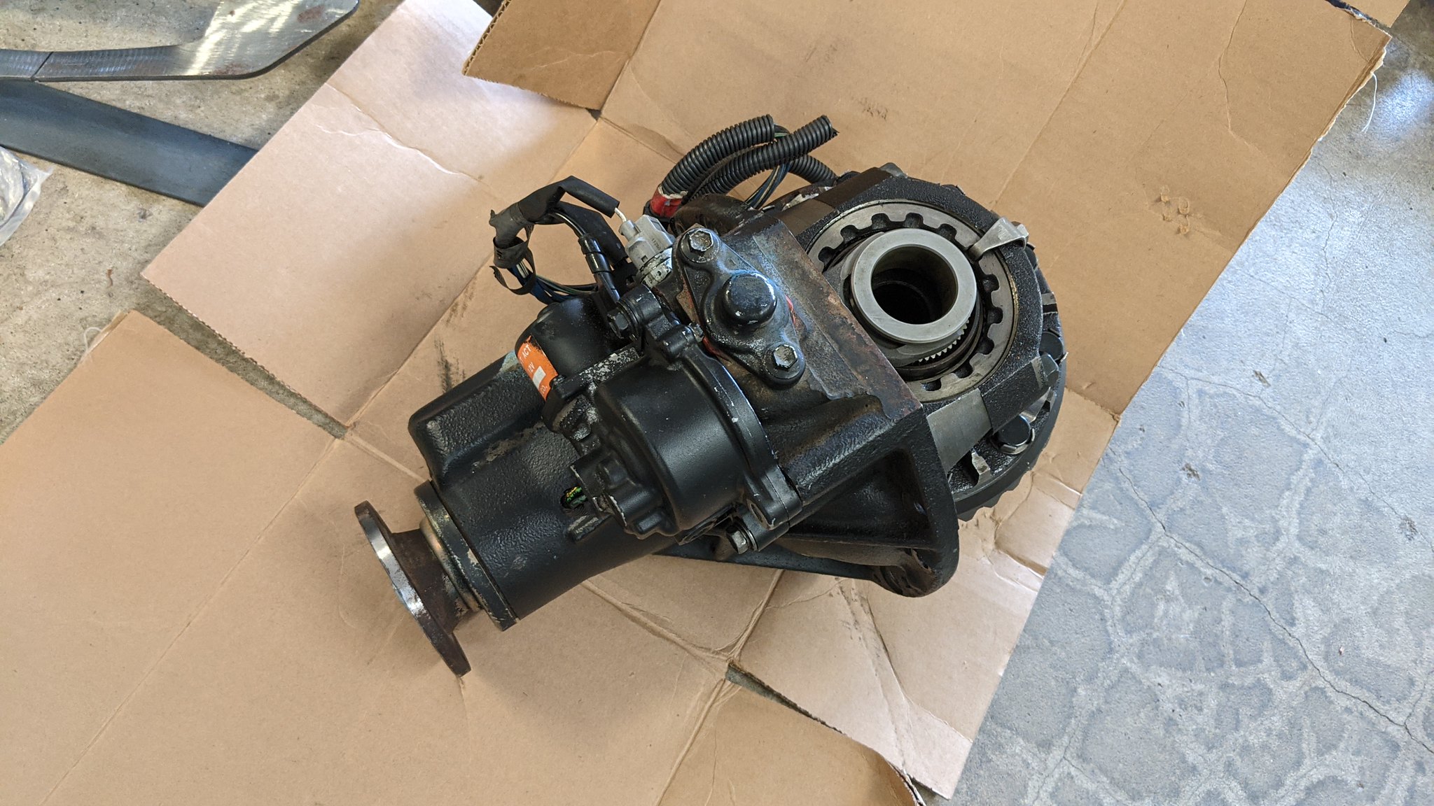
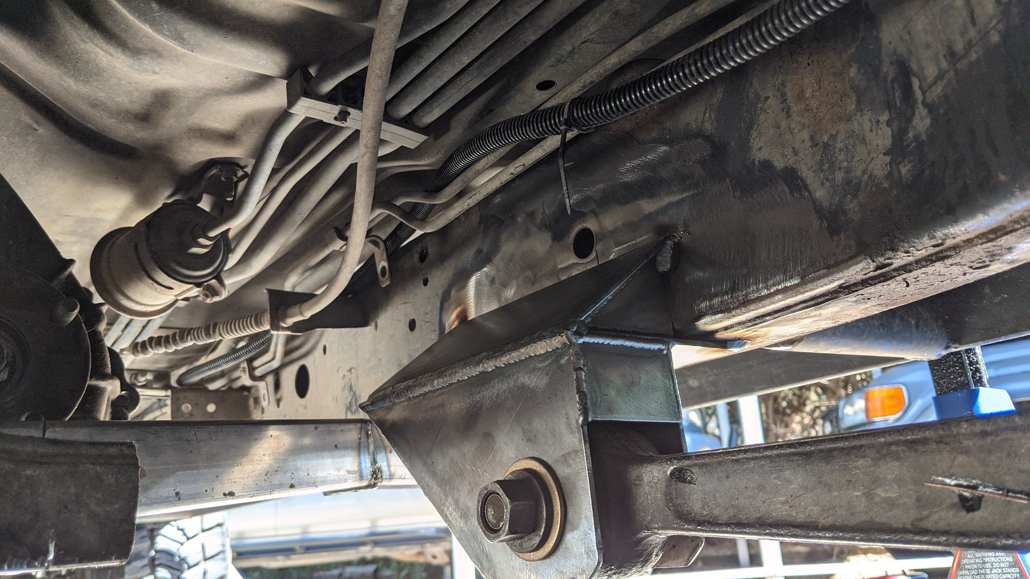
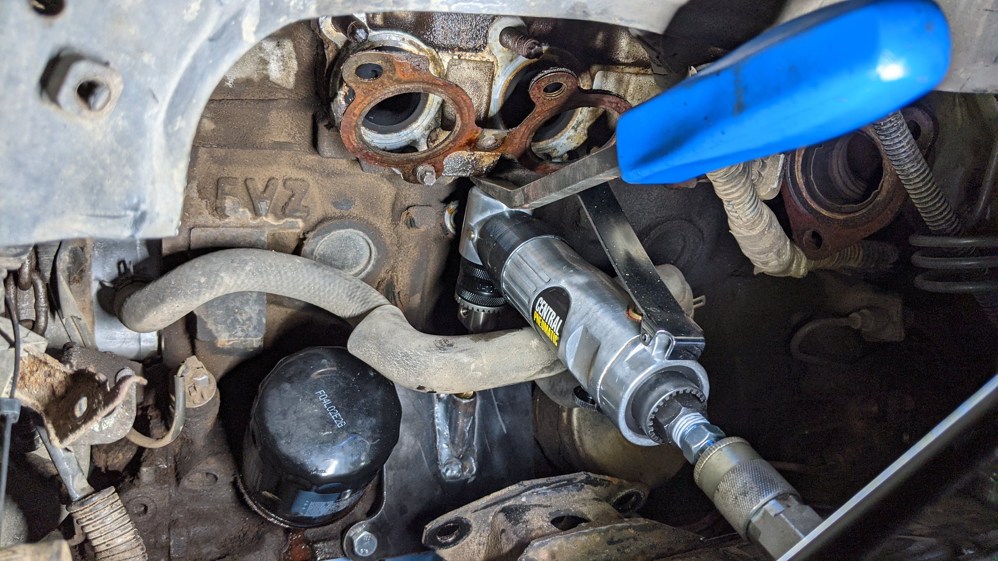
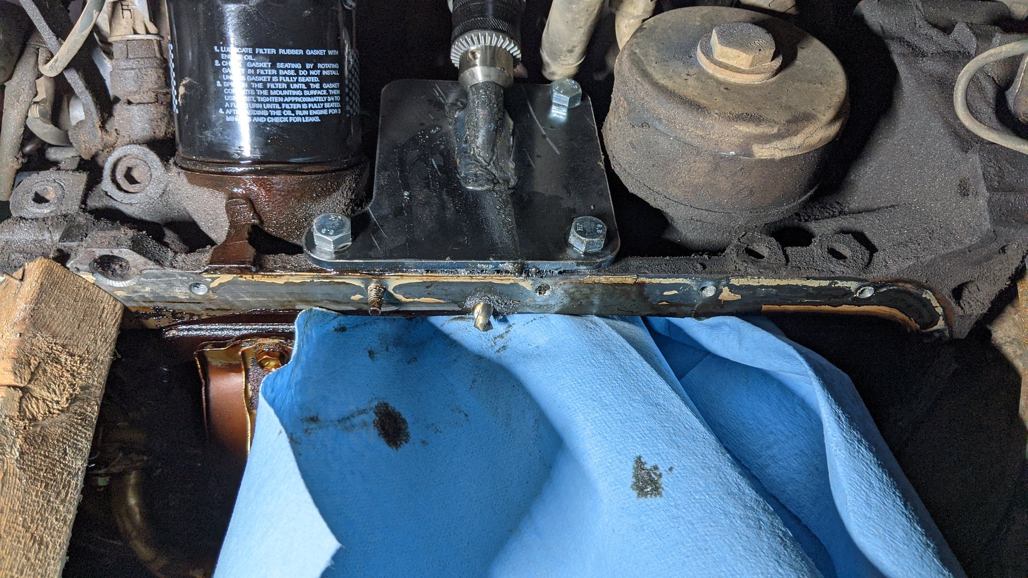
After putting together and taking things apart several times, I finally had the plates tacked on, and the steering box mounted temporarily. You can now see that he filler piece I made is un noticeable. I then re attached my string to see what the steering angles will look like, and I am reasonably happy. I think the truck will need to go up an inch or 2 , but it gives me a really close idea on where things will land. Then I tacked together a coil mount to start eye balling things. I cant really go any further now until I pull the axle out and swap the oil pan. The IFS pan is in the way of me making a panhard mount and getting a temp panhard bar in place to start fine tuning the side to side, as well as setting in the coil mounts. So that is a project for this next weekend.

51460871569_6278ce892c_k.jpg

51461089540_7a73d08c0c_k.jpg

51459373262_a3f5652ba5_k.jpg
 
Sep 19, 2021 at 7:29 PM

Small Sunday evening update.

Not a whole lot to report this evening. I took all of this coming week off, so I wasn't planning on working on it much due to rain, but am still a bit bummed by the silly road block I hit.

Yesterday, the wife and I went to a local favorite wrecking yard of ours to look for some parts for a friend, and a steering shaft. I fortunately got a complete one off a 3rd gen 4x4 pickup which will be necessary for adapting the steering column to the mini-truck box.

51495323340_ca0bbce302_k.jpg


I also received the drill guide for the new dip stick tube from Off Road Solutions this week.


51495106354_b4e35d4ab2_k.jpg


With the drill guide in hand, I decided to work on getting the oil pan swap out of my hair. I first had to drag the axle out from under the truck. From there I got the oil draining while I worked on removing the drivers side exhaust manifold. It was a little time consuming, but luckily all the fasteners came off without anything breaking. Afterwards I dropped the oil pan, and removed the dip stick tube. From there, I supported the drivers side of the engine VIA the alternator bracket while I took the engine mount out.

51494617763_cc0c4582b8_k.jpg


With everything out of the way, I took a very quick moment to scrape off the bigger portion of 17 years worth of caked on crud. Generally, I get really out of hand and clean everything to make it look new again. I knew I was limited on what I could actually do without spending a ton of time I couldn't afford to spare, so it was time to exercise some self control.

You can see marked in pink, the spot in the casting where a hole may have been drilled.

51494617598_968c3f1908_k.jpg


Once I bolted the fixture on, I quickly realized that I needed a right angle drill. At this point, it was about 4:35 PM and my local Hobofreight was closing at 5. So I ran 10 minutes down the road and purchased a drill. Unfortunately getting a late start today, and frankly not being that motivated bit me in the ass. Once I got home, I discovered that the particular drill I got was too fat to fit. I was debating on the one I got, and just a cheap air drill. I chose incorrectly.

51495102699_75ecf719ba_k.jpg


After bringing much shame to my family for such a mistake, I had to find a block of wood to support the engine for the night. Luckily, with having the week off, I should hopefully make a large amount of progress. Tomorrow morning I will go exchange the drill for one that should fit better.

51494393806_e570581593_k.jpg
 
Sep 20, 2021 at 9:00 PM

Well, I made a little headway this evening. Today turned out to be a day full of chores so I can be free hopefully the rest of the week.

This morning I went and exchanged the electric right angle drill, for this air drill that actually fits. So much hassle to drill 1 flippin' hole :sadviolin:

51499012579_f380d8857b_k.jpg


With a shop towel blocking the windage tray, I began drilling. As soon as I pulled the trigger and started drilling, I knew right away there would be a better way to apply pressure. So I grabbed one of my pry bars to assist, and maaaan did it make life easier. It still took a while because my air system is pretty underwhelming.

51499012499_bd2f33ee72_k.jpg


After what seemed like an eternity, we made it through.

51499012304_ac0ea1c4ef_k.jpg

51498517863_aaac9c50f5_k.jpg


Here's where my evenings road block happens.

The kit and instructions from Off Road Solutions said to use a letter U drill(luckily I have a complete letter, number, fraction drill index up to 1/2"). It said to use a 3/8"(.375") drill if a letter U isn't available. A letter U is .368" which sounds perfect. Generally from my experience in the field, drilling without a pilot you can expect the hole to be a couple thousandths over sized. So I figured if it grew by about .005", I would be golden.

The union measures .3775". The hole after drilling measured....... .386":( 
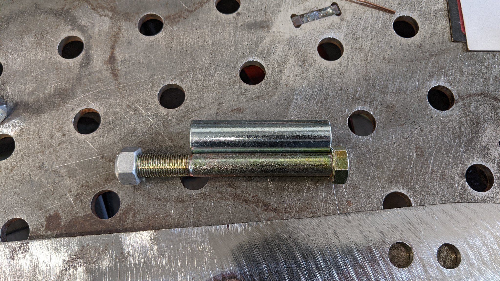
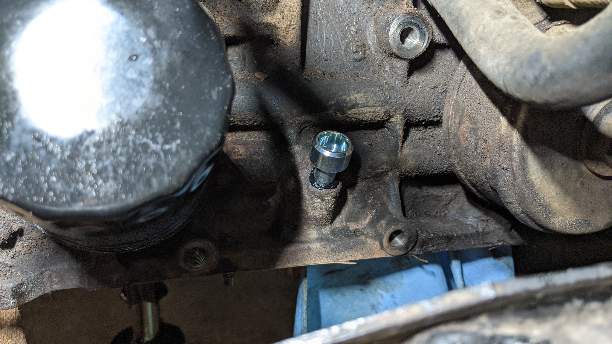
So now I have a .009" over sized hole for what I am to understand is a press fit application. My suspicion is, since the sleeve for the drilling fixture is probably a tad larger than .375", It walked on me(It certainly felt like it was) and that caused the hole to grow by almost .020". Tomorrow I will take some measurements of the drill and fixture to see what potentially caused this.

About all I could see trying, was coating the crap out of the union with Toyota 103 FIPG, and putting it in. I decided that I want to let it cure before installing the engine mounts. That way I can see if I am happy with it, or just say screw it and JB weld it in.

So I decided to just re-install all the exhaust with fresh OEM seals, and call it a night.

With any luck, tomorrow I will have the oil pan finished up(minus the final FIPG seal),engine back on the engine mounts, and the axle rolled back in.

51498295201_f714edcdc2_k.jpg
 
Sep 21, 2021 at 9:23 PM

Update time:


Today I made a fair amount of good progress, but not in the way that I thought. First thing I did was mark the oil pan to start cutting, then realized the caster being off might effect what I do. So I pulled our bone stock 80 onto relatively flat ground for some baseline measurements. It seems the truck has about a half a degree of rake, an about 3* of caster. I am shooting for about 4* or so of caster.

51505465546_cb7703047b_k.jpg

51505692168_826a2ee2f7_k.jpg

51504659482_1f738c0986_k.jpg


I ended up measuring about 0* of caster on my truck, and decided to take out the rear radius arm bolts and roll the pinion down. Initially I landed at about 3* of caster but that's not the end of my caster adjustments today.

51504659062_9a7c960893_k.jpg


At some point during my process I noticed the axle was shifted to the drivers side a little less than an inch. This lead me down a path of lots of measuring and adjusting. During which, I ended up seeing that I really needed to lift the whole truck about an inch to achieve the 4" of up travel I am shooting for.

51506395935_abd47e0aa6_k.jpg


At this point I decided to shift my focus from the oil pan modifications, to getting the axle where I wanted it, truck sitting at the new ride height, and go from there. So first thing I did was remove the windshield wash reservoir, and tack on the pass side plate.

51506395080_10c18e4635_k.jpg


With that done, I got my cherry picker out and lifted the front end up so I could lift the jack stands under the sliders by 1 click. Then I jacked up the rear and found a good/ghetto way to get the back sitting how I want. This gives me a very slight rake, and now I have gained about an inch up front.

51505464676_c5156d5312_k.jpg


After a lot of time getting things set where I am reasonably confident they will be, I see I have more room at the oil pan. It now sits with about 2.5* of caster, and I hopefully will be able to get it to 4*.

The rest of my evening was spent measuring to set the coil mounts, and getting a panhard mount figured out. I decided that I need the panhard mounted to keep the axle center. Then I can jack the pass side up and see when/if things will collide. I keep visualizing things moving up front as if it was a leaf sprung rig. But the panhard should keep the axle from swaying into the oil pan as badly as if it was on leafs.

With any luck, tomorrow I will have a panhard mount made and tacked in, and the coil mounts tacked in. I'm really hoping I can actually set on its own weight in the next day or 2, to see how much the springs compress.

51504658982_68a1b07930_k.jpg
 
Sep 23, 2021 at 11:26 PM

Well, today was a productive one. First thing this morning while running some errands, I stopped for a little material for the panhard mount. I also stopped for some cheap-o hardware to mock up the coil mounts.

When I got back home I began taking some more measurements. I decided to get both coil mounts fit up to help confirm my measurements for the axle being center. Somehow, the drivers side coil mount sits about 3/16" higher than the passenger side. But, the whole truck has a degree lean to the passenger side, so trying to make everything level to the truck is time consuming and probably had a little room for error.

This fab table isn't the nicest one I have used in my career, but it sure is handy as hell to have at home

51510384755_5e8a626f42_k.jpg


With both sides coil mounts firmly tacked in, I moved onto the panhard mount. Last evening I decided it would be easiest to use a 2-1/2 x 3-1/2", .250" wall rectangle tube to work from. The width of the panhard bushing sleeve was about 1.963", so it gave me a tad more than .030" wiggle room which seems perfect.

This didn't actually save much time doing it this way, but it saved a fair amount of labor. Its pretty plain looking, but it should be pretty solid.

51509684363_cd126ddd2b_k.jpg


With that mount made, It got tacked pretty heavily in. The panhard got a small pie-wedge cut in one place to bend a little , then sleeved to length to use temporarily. I grabbed the stock 80 drag link and it appears to be really close in length, so I put it in for the sake of mock up.

Everything seems to have landed in a place where I am pretty happy. The panhard is nearly perfectly matching the drag link for angle. I would say that the axle side could come up about 10mm to be absolutely perfect. The frame side is already as low as I could afford. As it sits, it will crash into the flat piece of steel right above the front, drivers side radius arm bushing at about 3.5" of up travel. That will probably get modified to accommodate for my 4" up travel goal.

Its difficult to see in the pictures, but there is a small 3/16" spacer under the drivers front, top portion of the coil mount. The frame dives right there so I needed it to be level to the rest of the frame. Oddly, the passenger side sat level without the spacer. I set them to match the same angle of the overall frame length(my driveway is at about a 1.5* slope)

All in all, I am really happy with the progress today. It's a lot more visual progress than the last several updates. I am getting pretty close to setting it on some coils to see how it sits. Hopefully tomorrow I will have that milestone

51509684123_f91536c1f9_k.jpg

51510384015_e6873f04b5_k.jpg

51509456531_1e0297a5a1_k.jpg

51509456511_0b5f472103_k.jpg
 
Sep 24, 2021 at 7:10 PM

Today I hit a hard earned milestone!

This morning before I went to the gym, I needed to swing by my local welding shop for an aluminum carbide burr. I had been considering picking up another welding hood that was a little lighter. So I treated myself. My neck has a little harder time at angles after my accident in this truck. Also, not having to look through the extra layer of the grindshield is nice for welding small parts. This new hood also has the more modern lens with the colors being more true which is really handy. I have 2 of those Speedglas hoods and love them. But it was time for another in the collection to help for other types of welding. It will probably get a dope ass pink/blue paint job before too long :D

51513044236_b658b0b859_k.jpg


After my workout, I blew the pine needles and cobwebs off ol' faithful to use as a poor mans lathe. Since the wheels have a lip that interferes with the front hub, I needed to remove that. So I bolted on the 2 front wheels for now, and let the truck idle while I evenly ground the lip of with a combo of the carbide burr and a flap wheel. I certainly died a little inside doing it this way, considering I used to machine parts up to 14 feet in diameter on my old vertical lathe at my last shop. But, I don't have those resources anymore unfortunately.

The first wheel turned out a little more rough than I wanted, but luckily it wont be seen. The 2nd wheel was much better. I'll do the other 3 wheels some other time when I am not racing the weather to get the truck rolled into the garage.

51513757049_a3f76bdc8e_k.jpg

51513972545_d43a69e875_k.jpg

51512241967_2a56235e26_k.jpg


With the 2 front wheels modified, I moved onto the coil mounts. I had to mark and drill the upper mounts for the center section that holds the bump stops. I got those mounted and finally set the truck on its own weight for the first time in a while. I set my upper mounts at the overall compressed length that our stock 80 is. It sits about an inch too high, so I will lift the upper mounts 1 hole which is 3/4". The front bumper, winch, a complete front end, and all the fluids should have it sit where I want.

Tomorrow I will drop the truck a little, then probably move onto getting the steering shaft in so it can be steered with the steering wheel.

51512240267_c01dabe6d0_k.jpg

51513968915_5d15769b21_k.jpg

51512238777_f73d9a2dd9_k.jpg
 
Sep 25, 2021 at 6:45 PM

Not a huge update this evening, but an update none the less.

Today amounted to figuring out some things critical to proceeding with welding stuff into place.

First order of business was to pull the coils and see what happens with the pinion when I simulate articulation to the pass side. I was pleasantly surprised at it not hitting the oil pan. The pinion rolled up too as you can tell by the bushing sliding down at the clamp. So there should be even more clearance in real life.

Not having to modify the oil pan is a nice bonus at this point.

51517884010_5317c7dda0_k.jpg

51516968306_f09176fba8_k.jpg

51516164142_4e0350aab5_k.jpg


With that sorted, I raised the coil mounts 1 set of holes and set the truck back down. It seem to be exactly where I am hoping it will sit. I'm not a huge fan of how far forward the axle sits. Especially since it think it looks silly. But that's just how it has to be unfortunately.

51516163997_185daa9474_k.jpg

51516163992_bd61d2f73e_k.jpg


From there I moved onto see where I landed for caster. I was pretty bummed that I ended up with only .5 degree of caster. So I decided to fiddle with that some to have a game plan. At first, I thought pulling the rear bolts on the axle and rolling the pinion down was the best way to keep the tie rod out of the radius arms. But then I realized I had it backwards. So I re-installed the rear bolts, pulled the front and then adjusted from there. It gave me way more adjustability.

It put me at about 4.5-5 degrees of caster which is way better. It gives me some wiggle room to maybe go up an inch if needed, an still have good caster.

I am going to look into caster correction plates to make sure nothing exists already before making my own parts. I want to keep the rear bolts in the factory spot, and just have new holes in front as seen in this picture.

51516163837_b7efb32213_k.jpg


After that was sorted, I started looking again at the radius arm mounts on the frame. It seems as though I needed to force the axle a fair amount to the passenger side for it to be center. I didn't want everything being under a lot of stress, and have bushings wear out prematurely.

I believe I identified the culprit. The drivers side radius arm mount seems to be tweaked some, causing it to force the axle to the drivers side without a panhard. So I am going to cut those tacks and make a minor adjustment, then see if it is better.

I figure putting a little more effort into these details will make everything go together and come apart much easier. Before I do any final welding, I want to be sure I am happy with everything.

I feel like I can slightly see the light at the end of the tunnel for this first checkpoint. The goal was for it to sit on its own weight and be movable before steady fall rain. If I can accomplish the below check list within the next couple weeks, I would be pretty satisfied. From there, I will clean and re-organize my garage and tuck it in there for a while.

-Permanently set caster.
-Make adjustments to radius arm mounts so they're not under tension
-Weld out everything
-Get a steering shaft in between steering column and box
-Complete the install of the oil pan


The rest of this work can be done in my garage. The main reason I did it out in the driveway, is because of all the mess involved with cutting everything out is easier to clean outside. With the majority of the big fab work coming to an end, I will be able to comfortably work on it over the winter in the garage.
 
Oct 3, 2021 at 8:44 PM

Update time!

Well, Although I reached the goal I set myself, I unfortunately didn't hit it with as many details buttoned up as I would have liked. The original goal was to have it sitting on an axle and movable by Fall. Technically I made that checkpoint today.

Getting the truck in the garage has sort of become a priority with all the dew in the morning air and rain. Even with it covered with an easy-up, I was getting a little surface rust developing on the bare steel. With this next coming week and weekend booked, I figured it was time to utilize the remaining sunshine and get it rolling.

Life has gotten in the way lately which has put me behind more so than I would like. That's how it goes though.

During my evenings this week I cut out the radius arm mounts and corrected some of the problems that was putting some stuff in a bind. The drivers side mount was at a very slight angle. They both were mounted a tiny bit wider than the axle side. So I built in some shims and got them re installed, helping everything go together much easier. I didn't take any photos of this because it would have looked identical to the previous photos haha.

I started off this weekend by wanting to make my caster correction parts and have the caster set. I got part way through that and haven't finished. But I at least have a design nailed down and the parts are about 50% complete.

Saturday morning we ran to our favorite local wrecking yard and scored this complete 80 series rear axle with elocker for a pretty damn good price. This is supposed to go under the rear of our 80 when it gets lifted and 37's stuffed under it. However I don't know that I want mix-matched lockers on that(ARB in front if this goes in back). So it might get sold off for a quick profit ORRR.... I'm considering swapping it under the rear of the Tacoma :D. I figured the benefits would be the full float, disc brakes, and a little more beef for down the road if I decide to do a 1uz swap(which I am considering for way down the road)

51548234968_42fe3f1705_k.jpg


With that unplanned trip out of the way, I set out to get a steering shaft in. I ended up fighting this for a little bit because I didn't realize the steering shaft I bought wouldn't mate up to my steering column. So I Hodge podged this together as a temporary setup to help moving the truck around. Making this temp shaft was in a way helpful, because it helped me decide how I am going to tackle the permanent one.

51548915760_dcb8e9b248_k.jpg


With that put in. I had to clearance the front vertical plate for the coil mount to clear the rag joint. It ended up still catching it when we moved the truck, so I will need to trim a little more off. I do plan on utilizing a stock rag joint at this point.

51547994401_9d4b16964f_k.jpg

51548915205_e42913eda0_k.jpg


With everything put together enough to proceed with moving it, I threw the coils in and the wheels/tires back on. The wife and I pushed it and flipped it around, and rolled it into the garage.

While I am bummed I am not a little further along(seems to have been the tone so far), I am still happy to have it at its first checkpoint. I'll take a short break on the project before getting back to work. The wifes car needs some work, and our landcruiser needs some maintenance before I dive into the rest of her build.

51548721944_f184582be6_k.jpg
 
Nov 13, 2021 at 10:45 PM

Well, the poor ol' girl has sat for over a month and I've felt guilty, so it was time to put a little time in on her.

The other day, I got back to work on the caster correction. I made these tabs and TIG welded on some washers that happened to be the same thickness as the stock brackets.

51673602923_d97ac9d4eb_k.jpg


After rotating the axle some I figured where I wanted to set it, and marked where to cut. Then it was all tacked on. I'll leave them tacked on for now until I take all my measurements before final welding everything up

51673602758_764b06e18b_k.jpg

51674038539_d75c4d540c_k.jpg


Last night I started messing with everything without the coils in. I was able to figure out that the bump stops compress about 1.25" with even distribution of weight. So I will probably plan for around 1.75" of compression and fine tune from there.

51678974180_e69037bfa0_k.jpg


From there I was able to see that the lower coil mount wasn't lining up very well, and was tilted by about 6 degrees. Since the OD of the coils is barely smaller than the inside dimensions of the upper coil mount, I want to ensure at ride height everything jives smoothly together. With this much misalignment in the coil, the coil is running on the mount up top.

51677288207_26a15f9411_k.jpg

51678341993_f0539cca8e_k.jpg


This basically meant more work that I wasn't planning on, but I feel is necessary. I decided to cut the lower coil mounts off and relocate them to line up better. This was fairly simple actually. I simply made a wedge to set the proper angle, and slide both mounts forward 1/2".

Everything is fit up for now. I realized during this process that I had been putting faith in my analog angle finder and its a bit sticky. My digital angle finder seems to be more consistent, and I have discovered a few adjustments that I need to make still. Luckily, I am waiting to final weld anything until I am absolutely happy with here everything is lading.

I'll be making a couple tweaks to the upper coil mounts, then fine tuning in the wheel base with my trammel points. Once that is set, I should be pretty damn close to welding everything up and moving onto other things.

51678974100_40a966b8e0_k.jpg

51678761484_16b3a88e71_k.jpg


Before tacking on the lower coil mount, I thought it would be beneficial to weld in 12mm nuts on the bottom side. That way I could machine some spacer pucks to fine tune in my up travel limits.

51678761509_f783fecb33_k.jpg


And where I left off tonight. It looks much better than the stock location. This has put a little wind back into my sail. My life is pretty busy so I won't be able to work on it as much as I would like. However, I am going to try and get something notable done each week, so I can actually make progress and post about once a week here and on my IG handle.

51678761489_d5aea620b0_k.jpg
 

Forum statistics

Threads
185,888
Messages
2,879,474
Members
225,497
Latest member
WonaWarrior
Top