Mate I suggest you just get a set of Little Giant steps and rework them to suit. They are a little spendy but nothing compared to trying to make your own. The best part is that the handle folds down and they are just 3 steps. Mine mount inside the door and I just put them out when needed. Missus thinks they are about the best modification we have made.
Link to steps
Bevan, I believe you have solved the step problem in one move! :clapping::beer:
It looks like the 2-Step model floor to 2nd step measurement is 17-3/4", according to one
Amazon reviewer, which should be just about right for my rig. Plus, these steps look like they would be just about right to reach a bag awning mounted on the side or just above the rain gutter, which is something I would not be able to do with a mounted set.
I do like the idea of self supporting steps though, in case of mud or uneven ground. But, the 2-Step model is less than a hundred bucks on Amazon, so I can live with that.
")
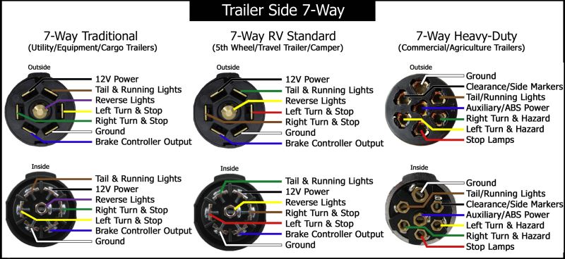
Also on your tail lights. Maybe I am missing something but doesn't the standard 7 pin from a ford run the indicators separate to brake lights. The conversion for all the trailers I have had over here is done at the tow vehicle. And is just for the 4 pin setup. So why don't you just run a new 7 core straight to the back of the rig and wire it in. Preferable with a descent double insulated cable instead of the flat ribbon and corrugated tube that most trailers have. Like this stuff.
Nope, The 7 Pin connector doesn't have a separate wire for the brake lights, since in a two wire system it's the same filament in the bulb. It has a right and a left turn indicator wire, and it uses these same wires for the brake lights, but doesn't pulse the signal through the flasher relay.
John is correct about the brake and turn being combined on my truck. Here is what I have...
This is a photo of the connector on my truck, which has since been replaced with a new but exactly the same piece.


I ran into this a few years ago mounting trailer lights on a temporary bumper, due to the OEM refrigerated box being removed. The issue stemmed from vehicle wiring that did not match up with the wiring in the trailer lights.
The Upgraded Heavy Duty Modulite Circuit Protected Vehicle Wiring Harness # 119190KIT may solve your problem.
Check out
https://www.etrailer.com/p-119190KIT.html
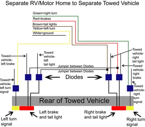
This kit uses a powered converter with circuit protection to safeguard your vehicle and the module. It also includes everything necessary to hardwire it to your vehicle. Be sure to use the included tester to make sure you have the correct wires before splicing. The colors on the trailer harness are as follows below.
Green = right turn
Brown = tail lights
Red = brake light
Yellow = left turn
White = ground
Black = 12 volt battery lead
DzlToy, I'll study that converter tomorrow when I can call them and ask questions if I need to.
I think what I may do is build a small mock-up out of plywood and 2x4's so I can mount all of the lights in their respective locations and wire them up for testing by actually plugging them into my truck, before mounting anything on the ambulance module itself.
Thanks guys for all the help...