preliminary electrical drawing for scrutiney

bansil

Adventurer
I hope this is the right section

I am posting this so I can "see" it from a different light :)

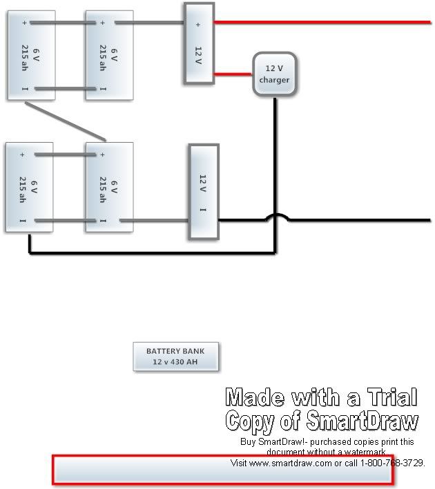
Biggest goal is to keep the fridge going come hell or high water
The inverters will be plug and plug so if one goes bad it's as simple as unplug and plug into another one

No transfer switch since this is our bus and others will not be using it (we can plug and unplug as we see fit; also it will be built in stages so we can use it as we build)

So going down the road the only inverter on will be for the fridge (the others can be turned on if needed)

When stopped if we choose we can unplug the inverters (to stop back feed and incase accidently turned on)) and plug in either shore or generator power
This will then allow all "inverter breakers" as well as ac and water heater to have power

The plugs mounted on/in the box will be male so that there wont be a live end when connected to power also the plug ins will have flip down doors so prying fingers can't test the breakers

My plan is to have all circuits grounded the way they where if extension cords where used (mmmm that doesn't make since :?)

Generator is not grounded to anything so it’s like using a big extension cord only with circuit breakers

Invertors are not grounded once again like using an extension cord

Circuit breaker box will be isolated from vehicle ground and all outlets will also be isolated from vehicles shell and tied to the box so that all circuits and box are "a unit")

Should the electrical boxes be grounded also like a house with a short wire from receptacle?

The inverters will just tie in the same way inside the box

Will this work?

In theory(mine :D ) we should be able to test shore pole to insure proper grounding and then we plug in and the shore takes over grounding...is that right?

Or will I start popping the camp ground fuse?

Remember this is just the start so any ideas or wisdom will be listened to

BUSELECT3-1.jpg


I know there is a lot of redundancy built into it, I am using a lot of acquired stuff from other projects and this will be built in stages so we can use the vehicle this summer like a steel tent and add “stuff” as time permits and more creature comforts are needed

I just want to keep the neutrals and grounds separate right to keep from turning the shell into an electricutioners dream ride, I have read so many stories of people leaning against a vehicle and getting shocked

Sorry so long thank you for looking
 

old_man

Adventurer
What are you using to charge the batteries besides the solar? With that much power, it will take a long time.
 

bansil

Adventurer
I plan to use the alt while driving(190 amp)using a solinoid to isolate when turned off and a battery charger when hooked to generator or shore power

I am just confused when looking at chargers right now:Wow1: I'm not really sure what I want or need

I see mention of 3 stage and 4 stage chargers just not sure "how much" charging I need,I know the trickle chargers are not what I need and some are fairly big and I don't want to charge to quick.

So I have been searching here for threads to read, I know I want a "smart" one that will charge,float and equalize

Any ideas that won't break the bank?
 

cnynrat

Expedition Leader
What batteries are you thinking about using?

This is probably a pet peeve of mine, but my experiences with running batteries in parallel has lead me to want to avoid that configuration whenever possible. It's typically done to gain capacity, but my experience is the capacity gain is often not realized.

Depending on the space available for batteries, I think you are often better off to use a physically larger battery with more capacity. So, in your system, it it were me I'd think about 2 larger 6v batteries in series, rather than the two banks of 2 that you have in your drawing.

Obviously, space constraints may dictate that you've got to compromise.
 

bansil

Adventurer
so is this right?

BATTERYBANK.jpg


I was reading on battery tenders web site and came up with the above.

So +/- is connected so it will charge.

Now If I connect the 12 V + from alt to the same spot as the charger that leaves me with no chassis ground to complete the circuit

So If I connect a chassis ground so the alt will charge batteries will that mess up anything else?

Should I also put a solinoid on the negative side so both +/- connect once engine is started?

Thanks
 

bansil

Adventurer
What batteries are you thinking about using?

This is probably a pet peeve of mine, but my experiences with running batteries in parallel has lead me to want to avoid that configuration whenever possible. It's typically done to gain capacity, but my experience is the capacity gain is often not realized.

Depending on the space available for batteries, I think you are often better off to use a physically larger battery with more capacity. So, in your system, it it were me I'd think about 2 larger 6v batteries in series, rather than the two banks of 2 that you have in your drawing.

Obviously, space constraints may dictate that you've got to compromise.
When you say larger what is your ref. point?

My wife can get me 6V 215ah batteries for $75 w/no core; so that seemed like a good way to go


and space wise I have basically 24in x 48in x 14 in space to play with
 

dwh

Tail-End Charlie
Just sipping my first cup of joe, and still half asleep, but here's a few thoughts (I'll probably elaborate later if I remember)...


[EDIT: Woops! Should have finished that first cup of joe before starting to type. This SHOULD say "any standard double pole double throw contactor". Fixed. Also link fixed to the correct type of contactor.]

Use a transfer switch. It doesn't have to be a fancy one from Iota or someplace - any old 30a rated double pole double throw switch will do. You can even rig an "automatic" transfer switch using any standard 30a double pole double throw contactor with a 120v coil:

http://www.alliedelec.com/search/productdetail.aspx?SKU=70185520

Cheap and easy to rig and then worry free after that.


An alternator/voltage regulator setup IS a trickle charger. Doesn't matter if you have a 190a alternator, or a 190,000a alternator; the voltage regulator will hold the "12v bus" voltage to a certain level, and however many amps the battery will allow to flow at that voltage is how many amps will go into the battery. Period. Depending on the resistance of the wiring and the battery, that'll generally be anywhere from 5a to 30a; and will taper off as the battery's voltage (and resistance) rises. Once the battery reaches a "surface charge" equal to the 12v bus voltage, there will be almost nothing flowing - even though the battery may only be at 80% charged.

There are special "battery charging" voltage regulators that will vary the output of the alternator to do a multi-stage battery charge. Without it, you've just got a trickle charger under the hood. Good enough to replenish a couple of amp*hours used to start the engine, not good at all for recharging a house bank.


A lot of times, people have problems with paralleled batteries, due to rigging it in such a way that the load/charge is not properly balanced through the battery bank. Here's a good page that explains how to do it right - and why:

http://www.smartgauge.co.uk/batt_con.html


(That's just a general comment - I have not actually looked at your diagrams yet. For all I know, you might be doing it right already.)


In general, in high voltage electrical wiring ("high voltage" in the electrical code sense - i.e., anything over 50v), neutral and ground are kept separate throughout the system, and only tied together at ONE point, and that's usually done in the main electrical panel and NOT done in sub-panels. If your rig is going to be plugged into a shore power system which already has neutral bonded to ground back at the main panel, then you DON'T bond neutral to ground in the sub-panel (or anywhere else) on your rig.

Also, a lot of inverters (and small generators) use what is called a "floating neutral" and when using one of those, you never tie the neutral to ground. Basically, with a floating neutral setup, there is no "hot and neutral" - what there is, is a pair of 60v hots which, when combined supply 120v. [EDIT: Sort of a smaller version of what happens when you combine a pair of 120v hots to get 240v in the panel at home.] You DON'T want to tie one of those hots to the frame or chassis or you risk creating a 60v potential which could lead to people getting bit.


For battery charging a house bank of flooded lead-acid batteries, the general rule of thumb for charger size is 5%-15% of the bank's total capacity. So if you've got a 400ah bank, then you'd need a charger sized between 20a-60a.

For charging off a generator, you would want to go to the bigger charger, to minimize generator run time (as long as the generator is large enough to handle the load of the bigger charger). Also, in terms of kilowatts per gallon of fuel, most generators are more efficient when loaded to at least 50% of their rated load.


You definitely DO want a good multi-stage charger. There is a problem with a lot of "3-stage" chargers, where they can get stuck in the absorb stage if there are loads running from the battery bank during charging. For that reason, you would want to use a charger which has a way of preventing that from happening and overcharging your batteries. An Iota charger with their IQ/4 control module added would be one of the best ways to charge a bank of flooded batteries. With the IQ/4 module, it will drop out of absorb after 8 hours regardless.

Without the IQ/4, the Iota is a "2-stage" charger, which has no absorb stage (only bulk and float stages). I would say for flooded batteries, you would want the IQ/4 mainly because it will bulk the bank up to 14.8v, which is perfect for flooded batteries. I agree with HandyBob about pumping up FLOODED batteries to 14.8v.

If you are sizing your charger up near the max of what the generator can handle - such as if you had a Honda eu2000i rated at 1600wC/2000wS, then keep in mind that most chargers don't have a very good power factor. Iotas for instance have a pf of .6. So if you'll be using a 1600w gen like the Honda, you should probably stick with a 45a or less charger. In general, the 1600w Honda *can* run a 55a charger...but it's marginal and if you go up in altitude, the power of generator's engine will drop off, and you might find that it runs the 55a charger just fine at the beach, but won't run it in the mountains.


That's enough for now...need another cup of joe.
 
Last edited:

cnynrat

Expedition Leader
You have a lot of space to play with.

It looks like your current configuration is sized for a theoretical capacity of 430 AH. In my experience you won't actually achieve that, but I assume that is your design goal.

Here's an option that would fit in your space. I am using Lifeline batteries as a reference because they are very high quality, they are local to me, and I've used them before in my camper and my trailer. They are not cheap however. There are other quality sources for AGM deep cycle batteries out there (Deka, Odyssey are two that come to mind).

You could get 400 AH capacity by using 2 6v GPL-L 16T batteries in series. These are each about 12"x7"x16". Note that they can be installed in any orientation, so you could lay two of them on their side for an approximate volume of 14" w x 16" l x 12" h. If it were me, I think I would take the 400 AH that I know I'd get from this configuration over the 430 AH that I might get out of the configuration you are considering.

This is going to run a lot more than the $300 you are going to spend for the batteries you can get through your wife's contact. So, if the cost is a constraint this may not be an option.
 

bansil

Adventurer
Those are nice batteries alittle $$ for me right now tho'

We will be using this project as it's built so we can see what we really need etc and still be able to enjoy it,instead of it sitting in the back yard for 2yrs while we build what we "think" we need.

My idea is to have nice "plug and play" system that can be upgraded down the road.

example:
All the electrical will be run in conduit(we like that look) and will allow for wire to be pulled as we expand.

So for starters we need the batteries to power our inverter for the fridge,not the best way to do it, but it does works for us now

everything else can be like regular camping

For the near future 3days every month(wishful thinking) and maybe a 1 week trip are our "glamping" plans

120 V Kitchen loads at first will be maybe a crockpot or water htr for tea

120 V bedroom may be a small tv/dvd player (probably a laptop tho for real now)

If she wants AC fine a window unit with a generator will work

A shore power hookup right now might just be an extension cord plugged in for the battery charger at the house and to power the fridge

This may not be a $$ glamourous rig,but we will be out enjoying the country:victory:
 

dwh

Tail-End Charlie
so is this right?

BATTERYBANK2.jpg

Eh..?

I take it that those two 12v doohickeys are bus bars?


I've edited your pic. Look at the power flow path:

The positive comes in to the right upper battery, then jumps to the left upper battery positive and then flows down to the left upper battery negative and then into the second (lower) series string. Then, it does the same thing on the lower two batteries only in reverse. In the lower string, the right side battery is in the path, but the left isn't.

What you have done there, is to cut two batteries out out of the power flow path. They'll act as tacked-on subsidiary helper batteries to the other batteries, but because they are not directly in the power flow path, the two batteries directly in the path will end up doing all the work.


Charging will do the same thing except the flow of the negative will turn left instead of turning right. Still, the lower left battery will be cut out of the power flow path.


As for the question about the isolator - the hot from the isolator should go to the positive bus bar, and then ground the negative bus bar to the chassis of the vehicle.


If you've got your bank wiring correct and balanced, then you should be able to just connect everything to the bus bars - batteries, solar charge controller, shore power charger, the wire from the isolation solenoid, fuse block, inverters - everything.
 
Last edited:

dwh

Tail-End Charlie
I appreciate all you do here as well as alot of folks...thank you for reading material:ylsmoke:

I see this as a the charger you talk about
http://www.amazon.com/DLS-55-AUTOMA...+AMP+Charger/Converter/Power+Supply+(12-volts


and the generator is 3300watt running

more solar will be added as time and $$ permits


Yup, that's the one. Only thing is - it doesn't do equalize. After 7 days at float, it will trigger what they call a "boost", which is really just running through the bulk and absorb stages again before dropping back to float. Of course, that requires that it be plugged in all the time. Otherwise, it will reset the 7 day timer every time you unplug it.

Still, the Iota with IQ/4 is extremely popular with the solar crowd who tend to run large banks of flooded batteries.

Also, by regularly pumping up the batteries to 14.8v, you shouldn't need EQ very often, if at all.


EDIT: But keep an eye on your water use. You will use more.
 
Last edited:

dwh

Tail-End Charlie
So, how to rig the batteries? Make two series strings, and parallel the strings at the bus bars. To keep everything balanced, make CERTAIN that the wire lengths on both strings are IDENTICAL.

Here's a cheeze-whiz diagram:

bank.jpg
 

bansil

Adventurer
I like cheez wiz...or did as a kid

Yes the 12V thingies are bus bars

I had it like your cheez wiz pic at first because it made the most scence

until I went looking at battery chargers and visited battery tenders web site FAQ area and saw that setup on the "hooking up" battery charger page
http://batterytender.com/resources/connecting-batteries-chargers.htm

and then that made scence

Would the "juice" not flow internally in the battery between +/- posts?

I am just trying to get a good grasp on this,because I have done this wrong in the past...it worked but not good or efficent

Thanks to post's here I now understand the importance of balance and using big enough wire etc.

So all 6 cables need to be the same; say with-in 1/4-1/2 inch?

Thank you again for all the Neewbe help
 

dwh

Tail-End Charlie
Would the "juice" not flow internally in the battery between +/- posts?

The power flow will follow the path of least resistance. That's almost always going to be the wire. It will have to flow through two of the batteries, because there is no other path.

Then there will also be a secondary flow to and from the primary batteries to the secondary batteries. That will be less than the primary flow, so the primary batteries will end up doing more work and wear out sooner.
 

Forum statistics

Threads
186,192
Messages
2,883,169
Members
226,050
Latest member
Breezy78
Top