Dead topic, I know. However, just to add information - the receiver itself is generally the weak point in this system.
Wait.. it's not shear or tension, but a bending load. Can you calculate the amount of bending force a bolt can take?
Not really. It's not a linear problem since the load on the bolt is not evenly distributed. The only way to do it properly would be a finite element analysis.
I think FEA would be overkill - that's like trying to kill a fly with a 12ga shotgun full of birdshot. It doesn't seem like winkosmosis is asking for an answer to four significant digits - just a lower bound, and that's trivially easy to get. Assume the bolt is simply supported and the load is concentrated as a point load in the center.
It really is a combo of all of them, but it is mostly bending.
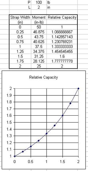
You can treat it like it is a simply supported beam and do a partially distributed load analysis on it, but first you need to know what the peak loading is and have an average width for the loop, while under load, where it goes around the pin...
Honestly, still overkill. A lower bound will do, and a concentrated point load gives you the lower bound solution. Assuming the strap distributes the load over a more broad length of the bolt will only give you a higher failure load, and as you said will be much harder to quantify. It also introduces assumptions which change with each pull if your strap is off center or inserted even the slightest bit differently. A point load lower bound is the true lower bound, you're not going to get a lower failure load as a factor of real world loading conditions. If I'm out working with this equipment, I don't really want to know what load my pin will fail at if it slips left and right. I want to know the lowest possible load which could conceivably cause failure.
I ran the numbers based on DaveInDenver's yield strength values of 92ksi for Gr5 and 130ksi for Gr8. You begin to get yield at the extreme fibers of the bolt at approximately 4400 lbf for Gr5 and 6200 lbf for Gr8. Those numbers are very low. However, that is a reasonable answer for winkosmosis' question - specifically, those are the lowest pulling forces which could permanently bend the bolt.
If you estimate the maximum load of the bolt by assuming it fully plastic, a state it may not even reach before failure due to the comparatively narrow yield range of higher strength steel (particularly Gr8), you get 7500 lbf and 10,600 lbf. Potentially adequate in a pinch, however those bolts will most likely have to be cut out after use as mentioned above, because as they say, "They won't look like they used to." Personally I wouldn't count on more than the 4400 lbf and 6200 lbf mentioned in the last paragraph.
Pulling on one frame rail of a ladder-frame truck? I saw a P38 Range Rover destroyed by doing that.
Depends on what else you do with the vehicle when you're building it. I relocated my gas tank up 9" and plated my rear frame rails together with a 37"x25"x1/4" skid plate also intended to function as a shear transfer diaphragm, so in my case I wouldn't worry about loading a single frame rail. Most ordinary vehicles have a very weak frame once you start talking about extraction, as you said. The weakest point in a hitch receiver recovery is often the receiver itself, however.
... I had two bolt-on D rings (like the type bolted/welded to trailers) positioned just outside of the frame rails on the bumper of my YJ years back, and actually deformed the bumper by using a chain Y to which I attached a ComeAlong when pulling out shrubs. The bumper was OEM, 3/16" bent sheet (formed into a C channel). ComeAlongs don't generate all that much force...using one point would have been a better idea by far, even for pulling shrubs!...
C channel is exceptionally weak compared to a tube, and 3/16" is thin. You would probably have had the same trouble with a single attachment to the same bumper.
For some reason I missed the bridle part of that. If the receiver is mounted to a cross bar between the frame rails that is strong enough to take the strain, then I'd just use a receiver hitch. The ones on the Discovery, for example, are bolted to a crossmember. The Class III hitch I had on my Wrangler was uber strong and tied to the frame as well. I just haven't seen any cheesy Class III receivers, personally. Most tend to be really stout.
Of course, there's always the guy who bolts a 2" receiver to the underside of a bumper and thinks it's strong. :Wow1:
Interpretation of "stout" may vary. Michaelgroves is correct. The Class IV/V receiver on my tow rig is rated (to tow, I know someone else confused this earlier with pulling capacity) for 14,000 lb without WD hitch, 15,000 lb with. It is manufactured from 2.5" square 1/4" wall A500B tube, with a yield strength of 46,000 psi. This is typical for most heavy duty receivers. My frame width is 37". The end plates attaching to the frame are 5/16", which is not stiff enough to cause fully fixed boundary conditions at the end, so again assuming a simply supported condition is most reasonable. That heavy duty receiver will begin to yield during a pull at only 7600 lbf, and will fail at 9500 lb. You can easily exceed that force with a winch, let alone a strap recovery. It's stronger than a Gr8 or Gr5 bolt in bending through the receiver tube, but not by much. Either way, you're not going to manage a 10k pull with that setup without mangling the receiver and the bolt.
Personally, I will use nothing but the hitch pin in the tube in a pinch, if that is absolutely all I have. However, I generally always carry a
12,000 lbf rated, forged receiver mounted hook for all my strap work. Personally, I hate kinetic recoveries, and I'm not worried about the 12K rating, since the receiver itself will fail before the hook in all but my wheeling rig (I built a considerably more stout receiver for the wheeling rig, along with other frame reinforcement already mentioned, since I enjoy doing recovery). If I need more force on the wheeling rig, I have a pair of 1" shackles that attach to 1" thick end plates for my rear crossmember/receiver, each end of which bolts to two feet worth of frame using six 5/8" Gr8 bolts in shear. I'm in the process of building a matching front end, unfortunately I had to put the project on hold while finishing something else. Not all of the bolts are installed in the photo below, and you can't see the additional reinforcement for the receiver tube under the winch plate (which is not yet welded in this photo) either. However, it gets the idea across. You can also see the location of the 1/4 skidplate/frame reinforcement below, it has a rubber pad resting on it in the photo.

This is the sort of strength and frame reinforcement you're talking about when you start dealing with 10-20K forces. This rear end was designed for 36,000 lbf, with up to 18,000 lbf at either shackle. Even so, the limit for the receiver tube is still approximately 12,000 lbf based on the strength of the 4x6 crossmember. Note that these numbers, unlike the failure loads discussed above, also have a factor of safety built in and are working loads.
If you don't want to start plating your frame, there is no point talking about larger recovery forces. A receiver crossbar will generally fail long before a well maintained strap, unless you're doing kinetic recovery, which throws in a bunch of new variables. Most recoveries are performed at well under 10,000 pounds of force, and usually in the 3,000 to 5,000 range. At that range even a Gr5 bolt will usually work, but personally I'd rather use an insert so I don't have to worry about cutting a bent bolt out later.
") One is part of my recovery kit, where ever the kit goes, it goes. As for the cost, I built mine literally from scrap steel. The shackle came with Patch, so my investment is time only.
One is part of my recovery kit, where ever the kit goes, it goes. As for the cost, I built mine literally from scrap steel. The shackle came with Patch, so my investment is time only.

")