Sprinter 4WD Conversion Idea, GMT-800 IFS.

luthj

Engineer In Residence
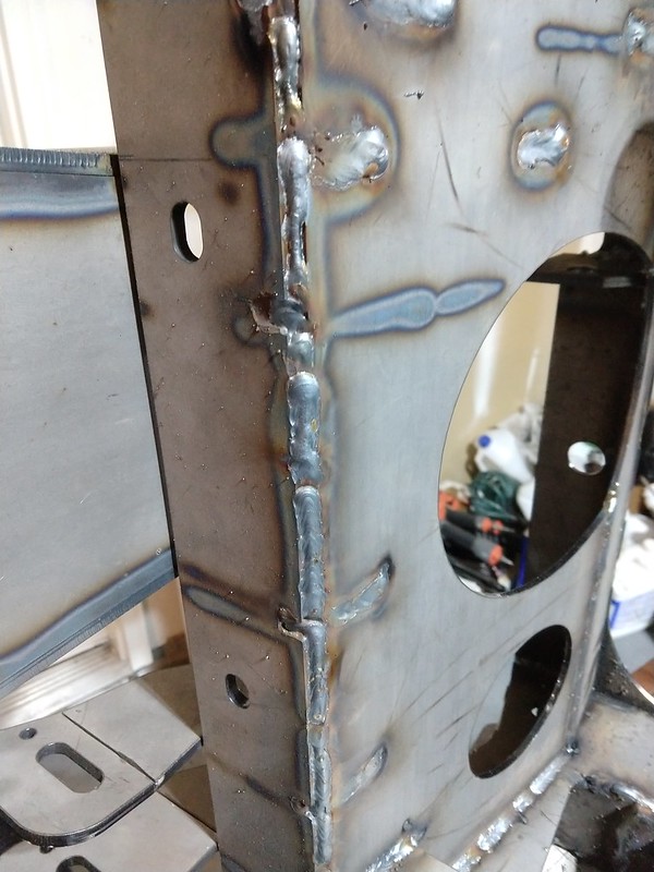
Still chugging along whenever I have a free hour. I noticed another minor issue. One of the alignment slots was missing, so I tacked in one of the uprights in the wrong place! Ooops.. Easy enough to fix. I had to break out the tape measure though.


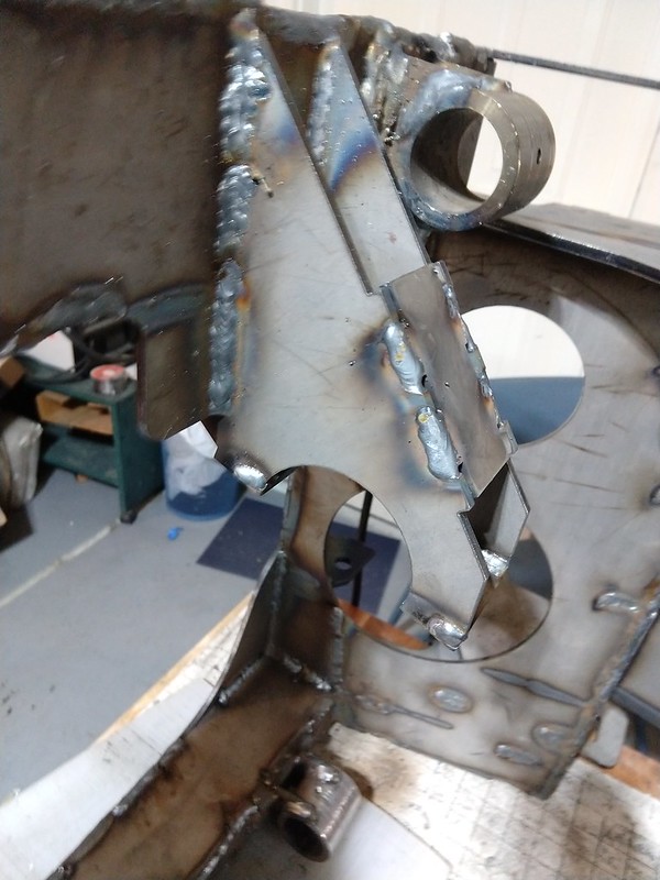
For some reason this tab didn't line up right. Its fine in the model, so not sure what happened.


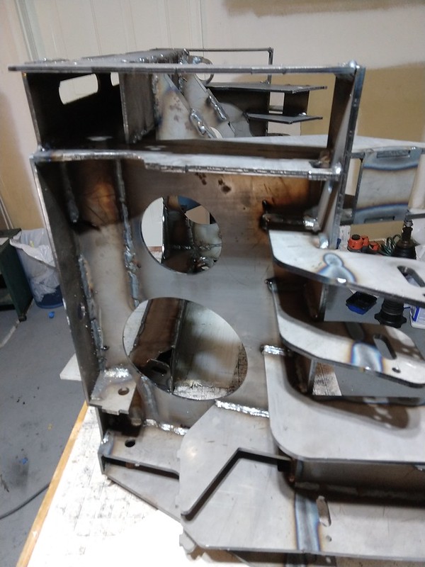
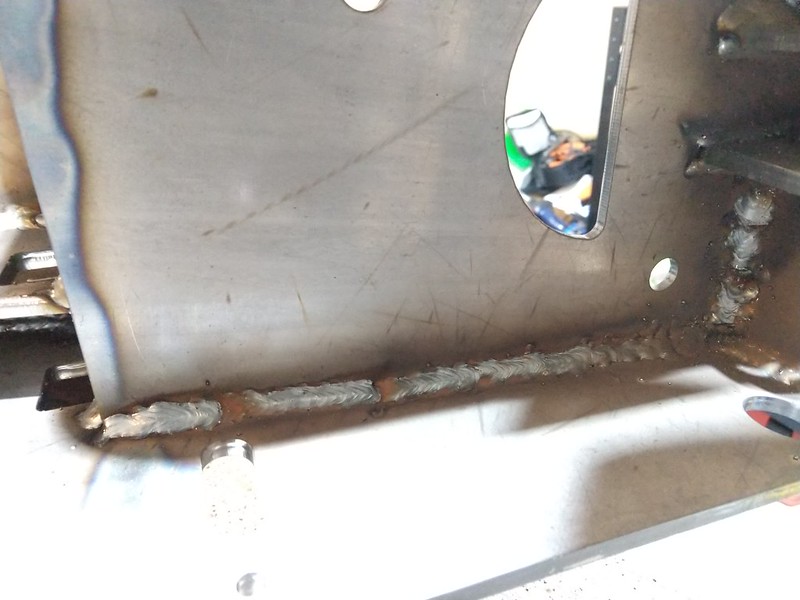
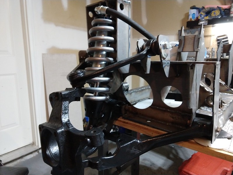
Getting close to completing the welds and closing the PS up.


luthj

Engineer In Residence
Just washers to hold it open while the welds cool. I got the PS diff brackets tacked in. So I should be ready to start welding everything wholesale. Going to take a while, as I need to shift the orientation to make the welds in position. Otherwise my crappy welding skills will come into play!
 

luthj

Engineer In Residence
Everything but the outer vertical plates is welded on. Maybe a few more hours of burning.


Did a little fitting with the rack. Looks like I will need to get the BFH out, as the mounts moved a bit when i tacked them (about 1/4" total). It going to need a few shims to get the angle perfect, but should be easy enough. The diff can be fitted with the frame installed, but the rack has to go in first, and one of the tie rods has to be removed. A pain, but no other options.


The casting boss for the lower mount was interfering a bit here so it got notched out a bit.


luthj

Engineer In Residence
Oops. I forgot to order one part, missed it on my spreadsheet. I will probably use one of the mail order companies for expediency. I can continue with the assembly and welding, just can finish without them.

1575134963635.png
 
Last edited:

luthj

Engineer In Residence
Fiddled with the inductance and feed rate. Definitely getting better puddle spread.

I am going to start bolting stuff on to see if the suspension actually suspends. Fingers crossed....


luthj

Engineer In Residence
My gut is 50/50 on the lower shock bracket strength wise. There is a slight thrust angle, out of the plane. So there may be some risk of fatigue 10 years down the line. I will need to evaluate once the suspension is loaded for slight movement. Worst case I get new ones cut medium carbon steel.
 

shade

Well-known member
Oops. I forgot to order one part, missed it on my spreadsheet. I will probably use one of the mail order companies for expediency. I can continue with the assembly and welding, just can finish without them.

View attachment 553824

Yeah, that looks kind of important. :)

Low and behold. The parts doth fit. (hallelujah chorus plays).


How close is the UCA to the spring? It's hard to tell from the photo. I remember that being one of the critical interference points when you were deciding between 2" and 2.5" shocks.
 

luthj

Engineer In Residence
That's great. Have you checked ABS sensor wiring yet? As much travel as you've added, you may have to adjust that cable as well.
I need to make a new harness for the gm sensor anyways, but I need to grab a donor bit from the junkyard.
 

Sharkfox

Observer
Now that this build is getting real, I can't help but wonder if you've considered having some of those parts (angles, channels, pans, etc..) formed versus all tab and slot assemblies. Especially if you plan to reproduce this at some point. I design sheet/plate fab assemblies every day and am always looking for an opportunity to substitute numerous inches of welding and fixturing for a couple quick hits on the break.
Either way, keep up the good work! Great technical and inspirational build.
 

luthj

Engineer In Residence
I gave it a fair bit of thought. If I had access to a press break I would have done that. But the reality is that for a handful of runs, spread over a few years, the extra cost doesn't make sense. Especially since this is DIY. I guess most shops would charge an arm and a leg to setup and break such a small number of varied parts.
 
Last edited:

Forum statistics

Threads
186,070
Messages
2,881,676
Members
225,825
Latest member
JCCB1998
Top