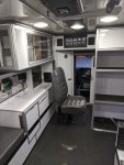
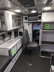
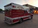
2002 International 4300 Ambulance

qcdstick

Member
I finally pulled the trigger on a medium duty ambulance a month or so ago after years of mulling it over. Reason for going medium duty is I want to use it as a tow rig to pull a 28'-34' enclosed race trailer. My plans for it are pretty minimalist compared to a lot of the stuff on here, I only plan on minor modifications. I will add shore/generator power 110v Air Conditioning, some type of fridge/cooler, a microwave or cooktop, and a queen size bed. This (combined with the existing 110v shore power system) should be enough for me to register it as an RV and suit my wife and I's needs for weekends at the race track. The rest of the cabinets inside and out will likely be used as is and i don't see a good reason to need to change them. Plumbing / shower / toilet isn't a concern since those tend to be readily available at the track, no true off grid camping is planned. Might also use it as a tailgating rig during football season.

I've already gotten the graphics stripped. Some buffing of the paint will be required, I'm hoping to not have to re-paint (although the box is corroding in quite a few places) as I don't really mind the colors as is. Want to try and find a new end cap for the light bar, but otherwise things are in pretty good shape.

2019-11-22 14.18.22.jpg

Specs:
2002 International 4300 LP
DT466 230hp / 620 ft lb
185k miles / 11,800 hours
Allison MD 3060 Trans
8k front / 12k rear
Air ride
Air Brakes
1000w Fleet Power Inverter / Charger (FP 1000-12)
LED interior lights in the module
Newish batteries, and newer tires all around (although as it turns out the fronts are out of round and I may replace them).

I bought it from the fire dept who ordered it new and they were able to provide a full maintenance history as well as all original the documentation and manuals. I have a digital 100+ page Medtec Part Manual, as well as a 267 page Electrical manual in PDF format I can make available if someone needs it. The department seemed to be still putting money in it (namely tires, batteries, and kingpins) through June of 2018. It went on reserve status with minimal use starting in November 2018 when the replacement unit went in service.

2019-11-01 20.00.07.jpg


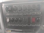
Has analog switch gear, and this relay panel seems great for troubleshooting. Everything is lableld with indicator lights on both the input and output side indicating if a given circuit is active. The big electrical manual seems to cover a newer digital system as well, thankfully they specified this one.
2019-09-24 17.57.20-1.jpg


2019-09-24 18.04.20.jpg


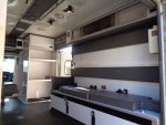
Walk through from cab to module

2019-09-24 19.02.08.jpg

One of the things I really liked about this unit is that there is no rear cabinet on the passenger side so the squad bench is long enough for a queen sized mattress as is. I haven't seen many units configured this way, and I'm a tall dude so any unit with that rear cabinet would require it to be removed.
16220_1_22.jpg


2019-09-24 19.03.36.jpg
 
Last edited:
qcdstick

Member
I bought a little window AC unit (Frigidaire FFRA0511R1E) 5000 BTU, supposedly has a easy start and came recommended for running off a small generator. I was able to run it off my friend's 2000w Yamaha inverter generator with the generator in eco mode. It ramps up noticeably when the compressor kicks on, then quiets back down. He has to couple two of those generators to run his 11,000 BTU rooftop AC, so being able to run off a single small quiet generator is a big win.

I haven't decided on a location yet. I have two primary options I'm considering right now.

2019-09-24 18.09.41.jpg


Option A
Mount it under the countertop, with the back of the unit inside the exterior cabinet behind. That way I can crack the door when the AC is running (or build some active ventilation for that cabinet to be able to leave the door closed in bad weather) but the AC unit itself remains protected from the elements inside the cabinet when not in use. There is a small flip forward door in that location that I believe used to be for a small garbage can for sharps that is otherwise useless to me. Removing that section of cabinet should give me JUST enough width to mount the AC unit. Big drawback of this spot is the unit will be pretty low to the floor, and the top of the unit at or just below the top of the mattress right at the head of the bed which isn't ideal for cooling performance or noise.

2019-11-02 10.03.18.jpg

Outside view. The box for the existing compartment is visible in the upper right, and would be removed and replaced with supporting structure to support the AC unit. Added bonus that I should be able to pick up power off the inverter right in that same cabinet.

2019-09-24 18.43.26.jpg


Option B
Set it on the top shelf (just below the top cabinet) on the full height shelving unit just inside the side door. The AC unit could sit on the shelf, and I'd have to "wall off" around the unit flush with the front of the shelf. I'd have to add some kind of active ventilation either down the wall between the shelves and the side compartment behind, or into the side compartment itself. This would be a more effective location for cooling, and there is power available in the back wall of the shelving unit, but will require more modification to vent the AC unit properly. Plus, I'd still have to do something with that door on the squad bench as that is about the only space on the ambulance that isn't useful as it sits.

2019-09-24 19.02.08.jpg
 
Last edited:

qcdstick

Member
Needing to troubleshoot a couple things.

Air Dump
There is a switch inside the rear doors on the passenger side labeled "AIR" that doesn't do anything. Plus, I think the unit should dump when the rear doors are opened (not something I want it to do, but it seems the dump system is not working in general). When we removed the license plate assembly, there is actually a 3 position switch hidden in the top of it as well, which I assume may have been for manual control from the outside? If so, that's pretty slick and probably exactly what I would want. I'm envisioning putting a control in the cab, and also at the back (that license plate location is perfect) for lazy mode hooking a trailer. Squat truck, drive under trailer, raise back up. Based on how the suspension leaks down over a few days, i have a solid 6" to play with travel wise. Could be all done from the front with a properly positioned backup camera, but a switch at the rear would be handy too. In any case, now that the license plate bracket is out, I have a mess of wires under the rear that I ASSUME are for suspension dump, just need to reverse engineer how it all works.

Light bars
They don't work for some reason. In fact, the master light/siren switch in general doesn't work the way the cheif said it's supposed to. Some lights work irregardless of the master switch setting, others (like the light bars) not at all, and others switch on/off with the master as they are supposed to. What's extra weird is I know when I test drove it they worked, but not when I picked the unit up. Pulling the switch panel out of the dash, I think someone messed with the wires back there. I could get everything to work by feeding power to the switches, so it's probably a rather simple re-wire. Not sure why someone would have tried to disable it, the cheif said everything should work, and if they WERE trying to disable things they did a crappy job because the flashers, strobes, wigwag, and siren all still work. Oh well. Not that I have any need for them, I just like things to work when they are supposed to work. I'll probably leave them hooked up, but wire a hidden (impossible to accidentally hit) switch somewhere to disable them so the master can't be turned on by mistake.

Batteries
The disconnect switch disconnects the truck, but not ALL of the module (but some?!). As near as I can tell the 3 chassis batteries are the only batteries on the truck (no house batteries). I'll want the battery disconnect to disconnect everything I think, right now the interior lights come on (low setting) when a door is opened and stay on for 10min. The exterior floods come on when a door is opened as well, which is a much larger concern as there are 4 tied to the rear door and they are halogen. I got a lot of the stuff figured out as far as how the relay panel works, and what module in that cabinet is which, but it's been too cold to be outside crawling under the truck tracing the primary battery runs.

Locks
The keys I got don't seem to operate the compartment locks. Or maybe they are just sized (as I've read here can happen). The module door lock in the rear doesn't lock (the side door does). I would prefer to get all of these working so I can store the unit outside and not worry about bad actors. Interestingly, on the dash there is a power lock button that trips relays in the relay cabinet. It doesn't lock any of the doors on the module, but I have to assume at one time it did? Closer inspection revealed wires running into the rear door that have become severed with use. No idea why the side door isn't working, the wires appear to be intact. Will need to open up the door panels somehow and investigate. At a minimum I need to get the rear door manually locking, but electric central locking would be a bonus.
 

Ozrockrat

Expedition Leader
With your locks. Check the mechanisms. The ones on my latest truck were bent purposefully so it could never lock some compartments. A little bit of muscle and they functioned adequately.
 

qcdstick

Member
Got the sharps cabinet removed and did a trial fit of the AC unit in the hole. The width is almost spot on, the AC unit went in with a bit of wiggling. Need to decide on a mounting height, devise a support structure, then fabricate some kind of panel to finish it off above and below the unit. This plan does seem to have legs though!

The cabinets seem to be 1-1/4" of plywood (a 3/4" sheet, plus a 1/2" sheet), talk about overkill!
 

Attachments

  • 2019-12-08 17.35.56.jpg
    2019-12-08 17.35.56.jpg
    226.1 KB · Views: 25

qcdstick

Member
Some updates:

Not much happened over the winter, but this spring I have been getting a lot done and even more things figured out. This COVID-19 thing may have ruined a lot of plans, but it has given me time to crank on some projects! Some of this stuff is probably obvious to most of you, but I had to figure it out as I went, so I'm sharing what I think I've learned for anyone who it may help.

Trailer Hitch and Wiring:
Got the trailer hitch done last fall - post here: https://www.expeditionportal.com/fo...-options-tow-hitch.184258/page-2#post-2706516

Finished trailer wiring and brake controller this week. Went with this universal 7 way kit from E-trailer because I've used it on a car before and it worked very nicely - https://www.etrailer.com/Wiring/Tekonsha/22550.html Basically its a little relay box, which allows you to tap the brake/turn/stop/reverse/etc feeds on the vehicle without placing additional load on the OEM circuits. The power is provided via the controller directly from the battery so the whole thing is pretty much invisible to the vehicle it is installed on and the trailer can't overload the tow vehicle circuits. Also handles duplexing the separate turn / brake lights of most modern vehicles into the combined brake/turn lights a trailer uses.

A note on brake controllers on air brake trucks:
In case anyone else is having to add a brake controller to a newish air brake truck, getting the brake pedal signal to the controller isn't as straightforward as you might think. In the end it all comes down to the computer being able to know that both brake switches (yes, there are two) are working, which is needed for cruise control so that the truck knows it will know when the brake pedal is pressed to disengage cruise to prevent the engine from fighting the braking. Thought it would be as simple as tapping into the pressure switch under the dash, however this truck is new enough it isn't that simple. Older vehicles, you'd have had a constant 12v on one side of the switch, and power would flow through the switch when the brake pedal was pressed, triggering the relay for the brake lights. This one runs it through a computer. The pin on the ECU provides a very low amperage 7.2v signal at rest (measured across the switch wires, 12v to true ground), which drops to 0.7v when the brake pedal is pressed. At a basic level, the switch is pulling the controller pin to ground when it triggers. But there are also redundant switches, each with a resistor so the computer can tell if one is bad, still provides 5v with the ignition off, and some other things going on that make it a pain to mess with. Not enough current on the circuit to even trip a relay coil. Pretty sure a solid state one MIGHT work, but even then you'd need a resistor and some trickery to make it work like it has a 87A normally on pin. Might give that a shot later. Since the ambulance already had dedicated brake wiring (separate from turn signals) at the rear, I just tapped that and ran an extra wire in the loom up to the front and got the trigger that way instead. For anyone else wanting an understanding of how the system works on these trucks (largely this is International, but others may be similar) there is a good explanation here: https://static.nhtsa.gov/odi/tsbs/2013/SB-10040739-2948.pdf If anyone needs help with this in the future, shoot me a PM, I (think) I have a handle on it now.

Air Dump:
This never worked from the day I bought the truck. Turned out to be a simple case of more faulty wiring from bad splice jobs. Starting at the solenoid under the truck and peeling back the wires, there were no less than 6 splices in the first 2' of wire. Simply replacing that section restored normal function where the rear dumps when the 2nd rear door is opened. There is also a momentary switch just inside the rear door that can be used to cancel the air dump. Basically, the primary (right side) rear door triggers the flood lights, and the left side the dump. All this worked as expected once the solenoid wiring was repaired. Having the rear dump is really nice for general work on the truck, and probably camping as well. Easier to get in and out of the vehicle, especially at the rear, plus sitting on the bump stops gets rid of the vehicle sway when someone is moving around inside. This system is again a switched ground, with constant 12v being supplied to the solenoid and the switch on the ground side. This made it easy for me to add a 2nd dump switch in the dash which will allow me to dump it any time I want, not just when the rear doors are open. This will be useful for camping as mentioned, but also for hooking a trailer because I'll be able to dump the rear, back under the trailer, and raise it back up picking up the trailer instead of having to mess with the generally rusty trailer jack. I get about 5.5" drop at the rear bumper. Dump and pickup is a bit slower than expected, probably because each airbag has a auxiliary cylinder T'd into it which means there is that much more air to add / remove. I think they do this to give the "spring" additional capacity for a smoother ride.

Light bars / Siren:
The front / rear light bars turned out to be really simple. The switches in the dash weren't fully wired for some reason. Splitting off the 12v that was going to other switches was all that was needed. The Siren/Horn switch wires were also disconnected. They claimed the vehicle was not decommissioned, but obviously someone started to. All the emergency lighting is set up behind a "Master" switch, so that it only works if the master switch is on. Simple enough, but the interesting thing is that the (i'll call them "slave") switches have 12v power all the time, so the master switching is actually handled in the relay board in the electrical cabinet. Similarly, the switches are illuminated when they are "on", but only when the master is also on. The way the switches are designed, is for the light to be "on" whenever the switch is in the "on" position, and since the switches have constant 12v, you would expect the indicator lights to be illuminated all the time, not just when the master switch is on. But this is not the case, the inidcator lights only come on when the related emergency light is actually working. The key to this is also in the relay board. Rather than the switches having a normal constant ground as a lighted switch normally would, they each have their own individual ground tied back to the relay board. When the master switch is on, the ground to the switches becomes active, thus allowing the indicator light to be illuminated if the slave switch is in the "on" position. Was kind of an "ah HA!" moment when I figured that out. Everything is working now. I'll not use the lights on the road, but I'm not above letting a kid play with them if they want to on private property in the right situation. I keep all the slave switches off and the master off. Still may add a 2nd master kill switch to avoid any possibility of an accidental activation.

The siren had always worked, but not fully. As mentioned above, the "Siren / Horn" switch wasn't properly connected, leaving me to figure out how it was supposed to work. Its designed for the OEM steering wheel horn button to alternately operate the normal vehicle horn (also have air horn on another dedicated button, two actually as the passenger has one also) or trigger the siren different ways depending on the position of the siren selector switch. When in siren mode, it can make the simulated air horn noise, or in a different mode it will cycle between 3 different siren noises and off each time the horn button is pressed. Wiring it incorrectly (as I did trying to figure it out before I realized it was tied to the horn switch) results in strange behavior where toggling the switch makes a different siren noise each time that wont' shut off... Thankfully I was doing this testing in our warehouse after hours! Later I found a manual for a similar siren system that explained all the modes which was a big help. The PA never worked, until it did. Fiddling with the wires must have fixed it. One of the most interesting things I found in the manual is the "Radio" mode on the siren which is designed to pump the two way radio traffic through the siren speakers. I don't have any use for THAT, but maybe I'll tie it into another audio source depending on how it sounds. Always stuff to play with and learn!
 

qcdstick

Member
Batteries / Primary power wiring
This truck just has the 3 12v chassis batteries for everything. They installed a battery disconnect switch, however it only disconnected the OEM vehicle wiring NOT the module. Not sure why you would do it that way, but I'm sure there was a reason. In my case, if I'm hitting the battery disconnect, its because I want EVERYTHING disconnected to avoid draining the batteries. As it was, even with the disconnect switch off, I could still find the batteries flat after a couple weeks of sitting without being plugged in. Thankfully, all that was needed to "fix" it was to move the module primary power wire from one side of the switch to the other. Far simpler than I feared it might be!

Next up was figuring out the timer, and how to keep module power for more than ~5 min without having the vehicle ignition on. Turns out the primary power distribution all happens behind the driver's seat. The galvanized box on the right is the 120v connections, the black box in the upper middle is the timer, not 100% sure what the bits in the middle are but I'm guessing some 20A and 40A breakers, and on the far side of the picture are two large relays.

2020-04-12 13.29.01.jpg

Specifically these two large relays:
2020-04-12 13.29.34.jpg
I guess one wasn't enough, so they wired them in parallel? The coils for each relay are controlled by the black timer box. The box turns on the primary relays when ignition power is supplied from the truck, and they remain on roughly 5min after the ignition is turned off. I'll be wiring up a DPDT switch which will allow me to either manually set the relays on while camping to power the module, or divert control to the timer box in the alternate position. Probably don't NEED a DPDT switch since the relays seem to always trigger together, but since each relay has its own wire from the timer box I'll keep the two independent. Interestingly, the relay board also has SOME 12v power at all times for some functions (low level dome lighting when a door is opened for sure, and I don't know what else) that does not pass through these big relays.
 

qcdstick

Member
Misc things


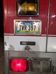
I relocated the license plate bracket. Snowball effect from installing the hitch, which meant installing a new step, which intruded on the factory license plate location. Pulled some lights on the left side to make sure I wasn't going to get myself into trouble, then cut it in on the left side of the truck below the turn signal. Always a bit scary cutting your first hole in a vehicle body. No going back now!

imagejpeg_2.jpg

2020-03-01 18.41.32.jpg


Reasonably pleased with the results. Only thing I don't like about this picture is it highlights the corrosion at the rear! I have my vanity plates on there now as well


Fuel tank was leaking, had rusted through under the straps. I knew this when I bought it, but keeping it below 1/2 tank seemed to eliminate the issue. Well, came out to a 8' puddle of diesel under the truck one day after driving it this winter (went to try and jumpstart one of our big class 8 trucks, turned out to be a bad fuel pump but MAN this thing can provide some juice!). So, new fuel tank got moved to the top of the priority list. Went with an aftermarket aluminum one. Went mostly smooth, the threads could have been better from the factory, and the filler neck was welded in a slightly different location which necessitated modifying my fuel tank cover some. All in all, not the end of the world.

2020-03-16 11.45.35.jpg

2020-04-04 16.55.13.jpg

2020-04-04 16.21.00.jpg


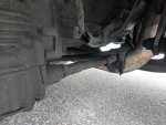
The BIG problem was, while I had the fuel tank off, looking under the truck I notice THIS:

2020-03-22 13.02.59.jpg

Yes. That's the transmission oil lines resting ON THE EXHAUST PIPE not all that far from the turbo! As near as I can tell, some genius decided they were too hot or too close, wrapped them with some heat shield stuff (good). BUT, had trouble packing the new thicker package into the OEM hangar, and replaced it with a much larger aftermarket hanger, which allowed them to sag until they rested on the exhaust pipe. How this didn't burn through the line I don't know. I can only conclude this was somewhat recent, and the few relatively short trips in cooler weather I took weren't enough to finish the job. With the melting, kind of hard to tell what is what, but the lines seem to be "ok" and not leaking right now. Needless to say, I swapped a OEM hangar back to that location, plus added one of my own to help, and got it as high as possible. So far, so good, no leaks or anything, but for sure something I'll be keeping an eye on. The other facepalm moment from this adventure, is when I decided to add another hanger, the natural thing was to use one of the bellhousing to engine bolts. Problem here is, when I was fitting the socket to it by hand, I almost thought I had the wrong size because it gave no resistance to spinning. Well, I DID have the right size, it was just a quarter turn shy of finger tight. Further investigation revealed that there were 6 bolts in a row this way! 2/3 of the bolts were tight, but someone clearly forgot to final torque a section. Apparently, good help is indeed hard to find...

I have more updates, but this is enough for tonight. Working on the bed now, and have some appliances in place. Should be prepping the race car, but since we can't race I guess the tow vehicle will have to do!
 

qcdstick

Member
One thing I've been kicking around since I started looking at ambulances is how to do a bed?! Lots of good ideas on here, but I decided to go a bit different way. Not the most obvious path, but to me at least it makes a ton of sense.

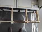
I went through a few iterations in planning, but this is what I ended up actually building for my first go. Goals were maximum flexibility and easy setup without tools. What I ended up doing was running E-track along the top edge of the bench seat, and also on the opposite wall, and using that as my attachment points for supporting my bed. Minimally invasive when you want the full box available, and provides convenient tie down points for anything I may want to haul in there depending on how I'm using the vehicle.

The black E track really came out looking pretty good, there was already a black stripe there anyway, the E track is just thicker.

2020-04-19 19.16.15.jpg

The factory seat cushions are simply velcro'd in place on the bench. So my plan is to extend that bench to the width needed and drop an air mattress on it which is quick and easy to inflate with readily available onboard power. Some other mattress may be sourced and put in eventually, depending how long we plan to leave it set up and what we are doing, but for now an air mattress is quick versatile, and easy.

Twin or Twin XL size:
will use this configuration if traveling alone. Leaves a nice isle and keeps the back useful if you want to leave the bed set up.

2020-04-26 13.05.18.jpg

Queen size
My wife and I like our space, so a big bed was a goal from the start. Initially, I had a design planned with L shaped legs similar to above. But once I realized that would leave me less than 8" space to the opposite wall it made more sense to just clear span it.

2020-04-21 18.12.36.jpg
 

qcdstick

Member
Now, for how it works. Some of the design choices may seem strange at first, however it is completely tool and fastener less, sets up fast, and all packs away in the compartment under the squad bench. Packing it away in there is what dictated a lot of the dimensions, and thus design choices.

Its supported from these E track brackets which are designed for exactly this type of application. Simply pop them in the slots boom boom boom for whatever configuration you want (more on this later). I will be marking the slots with a dab of paint or something to make them easy to identify in the future. Could leave them set in the e track as well, but they will do a number on your shins if you aren't careful!

2020-04-21 17.55.36.jpg


Drop your support beams across into the pockets, boom boom boom
This picture was taken before I trimmed them to the proper height, but you get the idea. I'll also be cutting an arch into the bottom of them because the thickness is overkill as it is, and will gain me more storage space under. Had to go 2x6 just to get the height I needed from the bottom of the pockets to 1/2" below the bench height.

2020-04-21 17.59.31.jpg

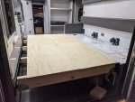
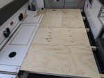
Lastly, drop your 1/2" plywood sections over top, and you are all set!

2020-04-22 12.40.49.jpg


Now, the eagle eyed among you may have noticed that in the prior post, the plywood was oriented one way, and in this picture two of them are turned 90 degrees. I designed it to be able to be set up either way! Each section of plywood is twice as long as it is wide so either orientation works equally well. The next thing you might be wondering is what keeps the plywood from sliding? Just 3/4" of space for each sheet is available on top of the 2x6 where the junction is.

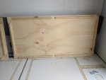
Lets flip one over:

2020-04-26 13.07.49.jpg

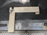
This is what makes it all work. As you can see, I have installed strips of parting stop (1/2" x 3/4") to the bottom side of each sheet. Each sheet is identical, so that you don't have to worry about which goes where in what orientation, just grab it and put it down and it will lock in and be good to go. There is a 3/4" perimeter all the way around, which helps keep each piece in place on top of a shared 2x4. It can't go too far in either direction because its held in by the one on the opposite side. There is also a 1-1/2" gap in the middle to grab a middle beam if installed that way.

There is still a bit more going on though. E track is spaced 2" between slots. If you notice, there are also gaps where a board can slot just inside of the outer perimeter all the way around. So you have a 3/4" lip, 1/2" of parting stop, then a 1-1/2" gap before the stop picks up again. This allows you to space your end supports 2" in from the normal (in this case 1'-8" spacing) so that the plywood overhangs the last support beam, instead of the beam sticking out 3/4" past the end of the plywood. This also allows it to "grab" the end supports much more which helps keep the whole thing more locked in. This allows you to space the joists 1'-8" or 1'-6" apart and be able to situate the plywood in either direction, or even do 1'-4" apart if spanning side to side which lets you add an extra bench or act like a chaise to rest your feet on.

2020-04-26 15.54.13.jpg
 

qcdstick

Member
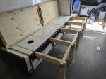
The twin bed L shaped legs can be used in two arrangements. Either installed to extend the existing bench into a twin bed, or installed on the opposite E track to make a 2nd bench on the opposite side with a small isle inbetween. Not really sure when I would use this, as the seating certainly isn't DOT compliant, but options never hurt!

The setup here is only slightly more involved, as I needed to introduce a lateral piece between the legs to introduce stability and lock everything in at the right spacing (so the plywood can't move enough to fall off the center support). This wasn't necessary when spanning clear across because the brackets on the opposite side prevented much movement.

The solution I came up with looks like this
The placement of each component works with the layout on the back of the plywood sections. When they are placed overtop, everything locks in VERY tight, shaking the entire assembly results in under 1/8" movement and feels SOLID which I'm proud of considering its completely fastener-less. That said, some tolerances are a bit TOO tight, so sometimes assembly can be a bit finicky to get everything to align and drop in properly. Nothing a bit of filing can't fix to massage the fit once I identify the regular trouble spots.

2020-04-26 13.07.40.jpg

2020-04-26 13.07.56.jpg


There are two components that make this up, 5 L shape legs and 2 braces. All 5 legs and both braces are identical, so placement doesn't matter. Because of human error, some may end up fitting slightly better in one spot than another but I'll do my best to massage that out. I really want to be able to just grab pieces and slap them down without worry.


The L shape brackets:
There is a pin that drops into a hole on the E Track bracket to keep it from being able to slide out (another thing that wasn't a worry when spanning clear across to the other E track). I just used a wood screw, installed it, then ground and rounded the head off. For these, rather than use a 2x6 and rip the width down, I instead used a 2x4 and built it up where it fits the bottom of the E track bracket. Each L leg also has a notch cut into the top which is used to key into the 2 lateral braces.

2020-04-26 13.08.57.jpg

2020-04-26 13.08.40.jpg


The lateral braces are made out of 1x4 material. Each brace is again identical, but the one is designed to turn 180 degrees from the other so they overlap in the middle. The other two notches are built out 3/4" so they fit tight in the 1-1/2" notches cut in the L legs. I could have cut 3/4" notches in 4 out of the 5 L legs, but due to the different size and placement of notches I'd have ended up with 3 different L leg parts instead of 1. Opted to make them all the same for easy setup and maximum modularity.

Once the 5 L legs are set in the E track brackets, drop the lateral braces in the slots which sets and locks in the spacing between each L bracket.

2020-04-26 13.09.23.jpg


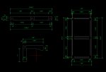
As I built it, some minor simplifications were made to the plan, but you get the idea.

Bed Components CAD.jpg


At the end of the day, setting up the bed is as simple as opening the bench, grabbing and setting E track brackets, dropping in the 5 beams/legs, then setting the plywood on top. The ambulance cushions then get pulled off and put under the bench where the bed components came from. Clean, simple, easy with minimal modification to the ambulance box. Might do something different than an air mattress in the future, perhaps ditching the ambulance cushions entirely and doing a 2 or 3 piece mattress that doubles as a back rest as some others have done.
 

qcdstick

Member
Well, not a lot of recent race pictures since racing is pretty well on hold for the foreseeable future. Don't have engines in either of the cars right now, and I should have been racing this weekend!

My wife and I do vintage road racing in the upper midwest. We run Austin Healey Sprites (aka MG Midget) in the small bore production car class.

My wife and I with our cars a couple years ago:

10953389_10102567598249490_5582154221183541761_o.jpg

A big field of just sprites / midgets (spridgets) at Road America for the 60th anniversary meetup

90180268_10156722327481493_732228878143062016_o.jpg

A few more from Road America

41991991_10105668820839560_329515044909875200_n.jpg

42087326_10156303746695528_3741935414202597376_o.jpg


A couple other random shots I found relatively easily

18319130_10155065350545528_8183866829176685831_o.jpg


18320513_10155065351340528_4938453542510362118_o.jpg
 

qcdstick

Member
Went racing with the rig for the first time last weekend!

Someone snapped a nice picture of the rig through one of the corner stations. Don't mind the trailer, it is as rough as it looks, but I can borrow it for free and it gets the job done getting our 2 cars to the track! Need to prioritize getting one of our own, baby steps.

103771610_2690585984563114_1698089194558358637_o(1).jpg


Also took the opportunity to scale the rig for the first time, with and without the trailer. This is fully loaded with our camping gear, tools, etc.

Truck has a 8k front axle and a 12k rear axle.

Without the trailer:
7,800 lbs front 8,820 lbs rear 16,620 total

With the trailer:
7,060 lbs front 11,240 lbs rear 8,740 lbs on the trailer axles, 27,040 total

So overall it seems the GVWR of the vehicle came in spot on for this application! Tongue weight is a big heaver than needed, came in at over 16% of the total trailer weight which is a tad high. Probably because the cars are light and my toolbox and pit bike sit at the front of the trailer. But, since the vehicle can handle the added weight it does make for great towing. Meeting semi's on 2 lane or being passed by a semi on the interstate didn't upset the rig hardly at all.

The rig struggled on hills, typically losing 5-10mph, but I consider this typical for a vehicle this size. Too soon to be sure MPG calculation came in at 8.3 for the trip taking 2 lane back roads, which was on the high end of what I expected it to be for sure. We went a different way on the return trip, running 63mph on the interstate with lots less stop and go. Not sure where that tank will come in at, so far sample size is very small but time will tell.

Camping in her went very well. Slept in there 3 nights, everyone kept asking how it went sleeping in there, my usual reply was "well, it isn't haunted!". We ran the AC pretty much full time (off shore power). It is not a big unit, and held the inside to just under ambient (but without the humidity) when in direct sunlight, dropped it 10-15 degrees below when we were shaded. Definitely going to want to insulate better, and prioritize finding ways to shade the truck on hot days, but it will work well enough for sleeping regardless which is really our primary need.

Organization wise, most of the exterior compartments were dedicated to spare parts, tools, and other race stuff (oil, gaskets, spares, etc etc). But I did outfit the exterior closet behind the passenger seat for chairs and tents. I put a couple hooks in the ceiling to hang 2 reclining lawn chairs on the left side, there are two 12'x12' EZ up tents on the right side, and 5 folding chairs as well. Nice to have all your shade / seating easily packed into one place!

2020-06-06 13.03.00.jpg


Just to the right of the side door when you enter the module is a unit of heavy duty shelves. We put our coolers stacked there (one per shelf), and on the top shelf 3 5gallon jugs of water. The jugs are designed to lay on their side and screw a spigot into the cap which basically gave us tap water all weekend. We didn't put a lot of thought into the positining, but it ended up working out really great because placed there we could open the side door and fill a glass of water without ever having to go inside the truck! This was the first weekend we didn't blow through two cases of water bottles (racing is thirsty business), and instead only a couple of re-useable jugs of water and re-filling our glasses which saves a LOT of disposable plastic use which is awesome. Frankly, I think the water tasted better too. I didn't get a picture, but next time I'll try to. No big fancy conversion, but it was extremely functional.

Inside cabinet use wasn't terribly notable. But this cabinet was important to us:
2020-06-17 20.24.55.jpg

The bed platform worked perfectly. Our luggage stowed under it drawer style easily. Pull out your bag, grab what you need, shove it back under. Since we are just weekending we didn't use any cabinet space for clothes storage. Mostly it is bedding, food stuffs, plates, supplies, etc.


I will say, sleeping on an air mattress sucks. Need to figure out something better that also still allows us to convert back to a squad bench without having to find a place to store a queen mattress... Thinking some 2 part foam deal that can function as seat / backrest for the bench then detach from the side wall and flip down onto the platform would be the way to go. Figuring out what to use and how to attach it is the hangup right now. Lots of information on making bed platforms, seemingly less so for comfortable sleeping mattress material that can double as a seat (sleeping being the priority).
 

Forum statistics

Threads
187,913
Messages
2,899,961
Members
229,071
Latest member
fireofficer001
Top