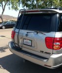
2002 Sequoia Limited 4WD

Sal R.

Active member
xmas201709-173.jpg

summit2018_32-172.jpg

484036

sequoiaNP01.JPG

DSC_2520-171.jpg

2019-12-31 07_47_03-166.jpg

FB_IMG_1596427316499-186.jpg

bear02-190.jpg

bear04.1-207-208.jpg

PXL_20210109_230200337-236-248.jpg
GOAL:
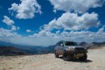
My goal for this daily driver is centered around exploring/camping trips and bumming around the mountains during the winter months. Because of her size, tucked and low slung were a requirement. I did not want to unnecessarily add width and height unless it served a real purpose.

MODIFICATIONS:
Suspension
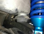
  • Front: 2" Lift
    • Fox Coilovers with remote reservoirs 880-06-420
    • Total Chaos uniball upper control arms with 3/4" bolt upgrade
    • Total Chaos polyurethane steering rack bushings
    • Solo Motorsports boxed spindle
    • Solo Motorsports lower uniball conversion with modified OEM lower control arm
    • Solo Motorsports heim steering
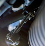
    • WabFab swaybar quick disconnect
    • @plastics_guy Durobump bump stop
  • Rear: 1" Lift
    • Dobinson rear springs C59-345
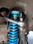
    • King custom shocks with remote reservoir with compression adjuster
    • Firestone Coil-Rite 4124 airbag kit
    • Califabrication upper and lower control arms
    • WabFab Swaybar quick disconnect
Drivetrain
  • CVJ remanufactured CV axles with high angle boots
  • 4.56 Nitro Gears
  • ARB F/R air locker
  • ARB CKMA12 air compressor
  • Rear differential breather
Wheels & Tires
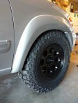
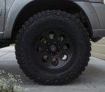
  • Level 8 Trackers 18x9, 0mm offset, 5.0" backspace (tubbed firewall)
  • 295/70R18 Goodyear Wrangler MTR (35s) current
  • 295/70R18 Cooper STT Pro (34s) old
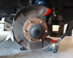
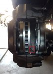
  • 4th Gen T4R 338mm "big" brakes
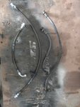
  • Crown Performance F/R sleeved and stainless steel brakelines
  • J.T. Brooks Pro tire deflators
Exterior
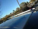
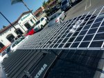
  • Off road Custom Design roof rack
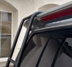
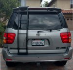
  • Custom rear hatch ladder
  • Rigid Industries 10" SR2 Driving/Hyperspot combo light bar
  • Rigid Industries D2 amber driving light
  • Rigid Industries Dually flood light
  • Rigid Industries D-Series SAE fog lights
  • nilight 5" LED rear flood lights
  • 44" single row driving light
  • 4" alley flood light (Qty. 4)
  • Stubbs Welding Ultimate SKO rock sliders
  • Custom F/R high clearance tube bumpers
  • Plano All Weather tactical gun case - 36"
  • RIGID Pro Tool Top organizer (Qty. 2)
  • NATIKA 720P front & rear night vision camera
  • APlusChoice 7.6x8.2ft side awning
  • Renology 100w solar panel with Wanderer PWM charge controller
  • AntennaMastRus stubby antenna conversion
  • Custom Grille
  • nilight LED rock lights
Interior
  • Pioneer SPH-DA120 HU
  • Alpine MRX-V70 4 +1 Amp
  • Polk fronts speakers
  • Infinity rear speakers
  • 10" Kicker sub woofer with custom enclosure
  • Remote rear/hatch window switch
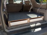
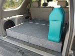
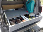
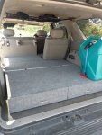
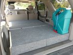
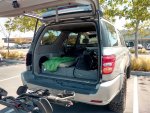
  • Custom cargo box
  • RAM mount
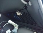
  • Attic cargo net
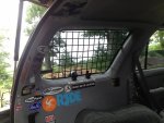
  • Custom rear hatch MOLLE panel
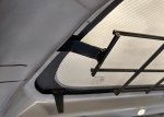
  • Custom window cover/storage panel
  • 6mm red LED ambient interior light
  • 20" white LED light strip cargo light
  • TOGUARD 5" rearview backup camera
Recovery
  • Maxtrax II traction boards
  • Bubba Rope kinetic rope 3/4"x20' 19k lbf break
  • Bubba Rope 7/16", 6"-soft shackle 32k lbf break
  • 3/4" D-Ring Van Beest shackle x4
  • ComeUp Winch Seal Gen2 12.5RS with synthetic line
  • Factor55 Flatlink
  • Hi-Lift 48" X-Treme Jack with Daystar jack handle Keeper
  • Deadman Off-Road anchor
Safety & Comms
  • Custom in-cab barrier net
  • Superwinch line damper (qty. 3)
  • Uniden Pro 520XL CB radio
  • FireStik II - 4ft. antenna
Miscellaneous
  • Waterport mounted with QuickFist clamps
  • ddpai dash cam
  • Trasharoo
  • Derale 13212 power steering cooler
  • Home Depot hidden snorkel
Future
  • Skids
 
Last edited:

Sal R.

Active member
MODIFICATION: Firewall Tubbing

GOAL:

Maximize clearance with minimal lift, run the biggest tires w/out have to modify the fender (since I wanted to keep the fender trim pieces), and keep the car streetable.

PURPOSE:
After installing the King Coilovers, and Total Chaos UCAs, I debated for a long time regarding 35s. Ultimately, I just didn't want the added weight of the tire size, the cost, the modifications to the fender, and sacrifice overall driveability. When I saw the spec sheet for the Cooper STT Pros and having great experiences w/ the ATPs, I was sold. Together w/ the Level 8 Trackers, average unsprung weight was 92 lbs.

I chose the Trackers because, eventually, I'm going to install 13WH brakes (338mm rotor), as opposed to the 13WL tundra kit that's commonly used. Since most 17" wheels have too much offset and results in too much tire poke for my liking, the 18s were it. It had the right specs, and personally, it looks more aesthetically pleasing for the big sequoia. The downside is that this tire size no longer fits in the OEM spare location. Right now, I'm not too fond of the idea of a rear swing out because 1) it adds length, 2) the tire weighs 92 lbs, and 3) I'm only 5' 9".

To do this right, I wanted the tires to clear everything. In order to truly prepare this cow for the trails, I had to tub the firewall to stuff the 295/70R18's.

DURATION: A weekend DIY'ing by myself.

MATERIALS:
Scrap Firewall Metal
Welder

COST: <$10

HOW-TO:
I pulled the shock assembly, bottomed her out, turned the steering wheel lock to lock, checked clearances, and marked where I need to cut.

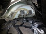
Stuffed and bottomed out:
IMG_20161124_144811226.jpg

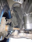
Clearance between tire and spindle:
IMG_20161124_144848279.jpg

**********! Hits the washer resovoir. Need to relocate and/or replace:
IMG_20161124_153231507.jpg

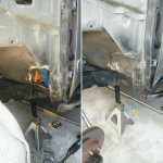
Once I determined where I need to trim, I went to town. I, then, weld patched the hole with some scrap firewall material I picked up from my local MAACO for free, provided I cut the metal myself, sealed the seams with Dynatron 550 seam sealer, then sprayed 3m 03584 Rubberized Undercoating. In addition to the firewall, I used some shears to trim interfering pieces of the fender liner. I'll patch ABS weld those closed too, eventually...
IMG_20180701_211033-307.jpg

The end result is a 34" tire (measured actual) that fully clears the inner fender more than the suspension can cycle, realistically. Based off my OEM height measurements compared against my current height measurements (not taking account wheel diameter), this setup puts my front end ~1.125 over OEM ride height.

Mission acccomplished!

However, I miss calculated. Because the tire is so tall, the fender and trim pieces needed clearance, as well. I thought I was going to be able to get away w/o having to work the fender, but that wasn't the case. The fender opening is more oval, than round. I was not ready to do that, so, my solution was to extend the bumpstops using a stack of appropriately sized washers to limit the suspension uptravel. With a 0.5" extension, I lost approximately 1" of uptravel. This brought my total wheel travel 7.5" inches. Minus the 1" forced limit, this wheel travel is consistent w/ everything I found on the web regarding Kings vs Icon Extended Travel COs. Icon Extended Travel COs full travel was about 9.5", measured actual.

Eventually, I'll probably replace them with Wheeler's Bumpstops, but it's hard to justify $50/stop for a something that just sits there most of the time...
IMG_20170408_104645.jpg

It was during this time that I noticed that the Total Chaos UCA's I had installed was hitting the coil buckets when the suspension cycled upward, which thoroughly pissed me off. For $800, I figured it would be direct bolt-on. I mean seriously? ******? In any case, I took an angle grinder to the coil buckets where there were interference. Afterwards, I sprayed on some 3M to keep the rust at bay. All clear.
IMG_20170324_111732614_HDR.jpg
 
Last edited:

Sal R.

Active member
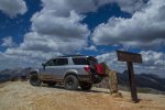
MODIFICATION: Audio Overhaul

GOAL:
Replace the failing JBL 10-speaker system.

PURPOSE:
When I purchased the car, the front speakers were blown and the rears weren't working. I decided to overhaul the system rather than try to fix it. To be honest, the HU was looking dated and needed a face-lift. I had never done an audio overhaul before, but once I laid it all out, it went pretty seamlessly. the12Volt.com is a great resource when I was doing research for this modification.

DURATION: <4 hours

MATERIALS:
Pioneer SPH-DA120 Headunit
Metra Wire Harness Kit 70-8113
Amp Wiring Kit
Speaker Wire
Polk component speaks up front
Infinity Kappa 6-3/4 speakers for rear
10" Kicker Sub
DP Audio Rearview camera
Metra AX-USB 3.5mm/USB extension cable - 27"
6ft Monster HDMI
6ft MicroUSB cable

COST: ~$1.1k

HOW-TO:
This is a fairly extensive install with a lot of trim pieces being removed, so I'll give an overview and stay on the highlights (and I'm pic limited).

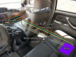
My approach for this install was to remove all JBL-related equipment (HU, front & rear amps, speakers) and re-use existing wiring for power, ignition, remote turn-on, and speaker hookups.

Basically...
  • HU wire harness > Metra wire harness > OEM connector (Ignition, Power, Ground, Amp Remote Turn-On)
  • HU RCA Out -> Amp RCA In
  • Amp Audio Wire Out > OEM Audio Wire Out > F/R Speakers
  • Amp Audio Sub Out > Sub
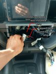
The OEM front amp location in the dash (already removed), as well as, connector I tapped:
2017-04-13 09_22_33.jpg

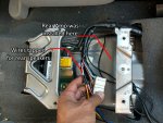
The OEM rear amp location under center console (already removed), as well as, connector I tapped
2017-04-14 16_48_312.jpg

To re-use the OEM speaker wire inputs, I had to know which OEM wire outputs from F/R amps drives the F/R L/R speakers. Searching around, I came across this:
Screenshot_20160413-204522.png

The wires highlighted in the red box are the wires I tapped to output the signal from the new amplifier. With this information in hand, I could move forward with the actual install.

Wire routing schema for audio:
IMG_20170412_1257421832.jpg

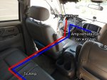
Wire routing schema for amplifier and remote turn-on:
IMG_20170412_1258081482.jpg

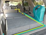
Wire routing schema for sub and rear view camera:
IMG_20170412_1305330572.jpg

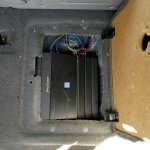
I mounted my new amp in the cubby below the 2nd row seat:
IMG_20170412_133740.jpg

Tapped wire for reverse signal:
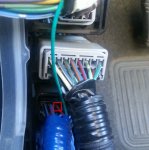
Under the driver's side kick panel, just next to foot rest, there's a plethora of wiring. Pictured below is a red wire w/ black stripe and silver bands.
reverse_lead_tap.jpg

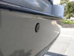
Rearview camera mounted on rear bumper face for maximum visibility:
If you mount a rear view camera like this, be advised to pick your spot carefully. Mount too low and you'll hit the steel rear reinforcement bar.
2017-04-13 12_03_03.jpg

There is a rubber grommet next to the Sub that allows the pass-through of the camera video cable to the outside/underside, as well as, power and ground to power the camera. I tapped the 12V socket next to the sub for power.
2017-04-13 12_04_16.jpg

For illumination, i tapped the green wire behind the dimmer knob.

Other misc mounting HU connections (USB x2, 3.5mm Aux, HDMI, etc.) are all routed down the center to inside the center console cubby to keep the cab clean and unspoiled. The removal of the rear amp created lots of room for clearance for such things. As a general rule, I generally cut into trim pieces that are easy/cheap to replace.
 

Sal R.

Active member
MODIFICATION: Custom Cargo Box

GOAL:
Efficiently utilize a cargo system to neatly organize gear constantly in the car and implement a modular sleeping platform/cargo bed.

PURPOSE:
I tend to carry a fair amount of gear ranging from tools to hiking boots at all times and keeping them totes was less than ideal. Also, the cargo floor was not level and it was not very comfortable to sleep on, even w/ an inflatable sleeping pad. Instead of spending money on a weathertech mat, I decided to build a lined cargo box.

Requirements:
  • Minimum height
  • Modular
  • Removeable
I did not want to diminish the car's function to haul big things, so keeping it low was a priority. Also, I wanted to be able to sit up and not ********** my head on the roofline. Evaluating the gear I carry, the resulting estimated max height of the cargo box ended up being 6.5".

Because I prioritized minimum height for the cargo box, I opted to build a extending platform when the 2nd row seats were in the up position. I could have built it w/ the seats folded down, but to keep it level, the box height would have been 9.25" and that was more than I wanted to sacrifice. Sure the additional space would be nice, but just not for me.

DURATION: 6-8hrs

MATERIALS:
Plywood panels 72"x48" (Qty. 4)
1x6 (Qty. 8)
26" Ball bearing drawer slides (Qty. 4)
Carpeting (as required)
Aluminum trim (Qty. 2)
Piano Hinge (Qty. 2)
Lid Support Hinge (Qty. 2)
T-nut Leg Level (Qty. 8)
Turnbuckles (Qty. 2)

COST: <$180

HOW-TO:
I'm not going into the nitty-gritty details since this is a pretty straighforward construction. My choice of design utilizes two columns of slideout drawers and top-loading cubbys. I chose a completely rectangular design so it makes removing the box easy (unbolt and slide out), as opposed to a shape that contours the interior. The box is bolted down in place using the factory tie downs.

Basic frame in place w/ cubbly lids loosely mocked up:
2016-03-12 17_37_16.jpg

Drawers installed:
2016-03-15 15_06_58.jpg

And finished:
IMG_20170412_130110117.jpg

IMG_20170412_130154447.jpg

Turnbuckles and shelf support:
IMG_20170412_125600093.jpg

I used the tie downs used for baby car seats in the box rear and steel tabs bolted thru the cargo rings for front securing it to body.

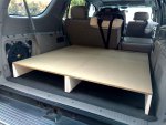
In addtion to the cargo box, I built extending pieces to convert the rear into a hauler/sleeping platform. It utilizes two pieces so it's modular and works w/ the 2nd row 60/40 split depending on the need.
IMG_20170412_130417492.jpg
IMG_20170412_130533057.jpg

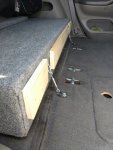
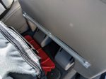
Not to waste a square inch of space, the space under the platform can also be used for storage on trips. The extension platforms are held up using "L" brackets bolted onto the underside of the 2nd row seats.

2018-12-13 12_23_56.jpg

The resulting sleeping platform ended up being 70"x48"x 6.25".
 
Last edited:

Sal R.

Active member
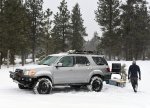
MODIFICATION: Custom Roof Rack

GOAL:

A more usable, modular roof rack system.

PURPOSE:
I always hated that to use the roof rack, you constantly had to move those silly crossbars around to the proper spacing. And it was ALWAYS a PITA, especially if you forget to grease them regularly. Not to mention, there's not enough cross bars to hold multiple pieces of equipment, luggage, etc. if there were different lengths. And I was never comfortable with things resting on my roof.

I considered RhinoRack, FrontRunner, and Gobi systems, but in the end, they all added height, too expensive for what they were, and, personally, not too pleasing to the eye. I love the lines of the 1st gen.

Inspired by fellow tree hugger jimsmola, and T4R wheeler, the.skid.kid, I opted to fabricate a drop in rack that was low profile, cheap (relatively speaking), modular, and cheap (double for emphasis).

DURATION: 8-10 hours

MATERIALS:
1/4" thick aluminum bar stock 96" length (Qty. 2)
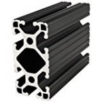
1"x2" 80/20 T-slotted aluminum extrusions 48" long (Qty. 13)
ABS Sheet (ASTM D4673, 1/2" Thickness, 12" Width, 12" Length) (Qty. 2)
Misc bolts

COST: <$450

HOW-TO:
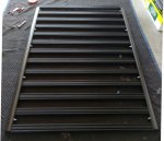
The process is pretty simple. The 1/4" thick aluminum bar would serve as the rails for the 80/20 T-slotted aluminum extrusions. The rails would, then, mount to the OEM roof rack to transfer the load to the roof supports.
IMG_20161203_144210894.jpg

For my design, I wanted the maximum cross bar count to transfer the load front to back of the OEM roof rack. The end result was 13 cross bars, spaced 3" apart. That is 5" on center. This yielded a flat rack 62" long, 47" wide.

41189Q9vkoL._AC_US160_.jpg

The attachment holes on the 80/20 extrusions are 1" on center and are not pre-tapped. I used an M6x1.0 tap to properly thread the extrusion.

Because I wanted the rack to sit within the lines of the OEM rack, I discovered thru measurement that the lowest part of rack would interfere w/ the roofline outer mold line. Two solutions available; 1) mount the drop-in roof rack outside the OEM roof rack lines, or 2) raise the OEM roof rack.

I opted to raise the roof rack using custom made 1/2" thick ABS spacers.
IMG_20170411_191956859.jpg

Steps:
  1. Cut rack rails to desired length (i.e. 62" long)
  2. Measure out cross bar locations (i.e. 3" apart)
  3. Mark crossbar mounting holes on rail 1" apart
  4. Drill and countersink cross bar mounting holes (so the rails can sit flush with OEM rails)
  5. Tap the 80/20 extrusions mounting holes (for 13 cross bars, that's 52 holes)
  6. Assemble drop in roof rack
  7. Line up drop-in rack to OEM rails
  8. Mark mounting holes and drill
  9. Mount to OEM roof rack
  10. Trace/transfer OEM roof rack feet to ABS sheet
  11. Cut ABS sheet
  12. Drill pass thru holes on ABS sheet
  13. Assemble all together and mount (Will need longer OEM roof rack mounting bolts. Home Depot has them)
IMG_20161229_110404484.jpg
IMG_20170411_192013739.jpg
IMG_20180410_124603.jpg
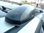
Because of the square nature of the cross bar, it generated a lot of wind noise. I used an old Yakima wind fairing to solve that problem.

Also, I knowingly sacrificed the pop up ability of the sunroof for maximum roof rack length.

I chose a T-slotted extrusion because I wanted to be able to use these drop-in T-nuts:

51vyOS+ZfAL._SX90_.jpg
Using these little (pricey) fasteners, I can have a modular system depending on the season and gear I'm planning to carry. The result is that I'll have a lot of custom fabbed brackets mounted to the rack using these T-nuts.

The minimum clearance of this rack to the roofline OML is ~3/8" at it's lowest point. Analysis has shown that a 200lb point load dead ********** on the center will cause that one bar to deflect no more than 1/8". Based on that, I'm good to go.

So far, 1) I've slept on my roof at my heaviest (190lbs), 2) carried about 300lbs of lumber, 3) carried 2 full size mattresses plus associated box springs.

Not too shabby, me thinks.
 

Sal R.

Active member
MODIFICATION: Rear Window/Hatch Switch

GOAL:

Add functionality to the rear window independent of key in the ignition.

PURPOSE:
I've spent quite a bit of time sleeping in the back of my Sequoia. Whether it was to get away, or for work, the back has been a home away from home. Depending on the season, it can get pretty stuffy or cold at times and it was ALWAYS a pain to grab your keys, crawl over into the cockpit, insert key, roll up/down windows. Especially so when you want to get some rest.

MATERIALS:
DPDT Switch
16-22ga Wire

DURATION: 2-3 hours

COST: <$15

HOW-TO:
I created a write-up here.

I used this switch, just because it was a very nice switch. In reality, you could use any cheapy DPDT switch.

I opted to route my switch in the rear cargo area and mounted easily accessible from my sleeping platform location or outside the vehicle, for convenience. It is located on the trim piece forward of the driver's side rear wheel well. It's just behind the 2nd row passenger seat. That way, it's accessible, but out of the way so that it can't get bumped when I have to haul a ton of...whatever.

IMG_20170331_120343.jpg

IMG_20170411_193243699.jpg

The switch I ordered came in pairs and I had thought to mount one on the passenger side, but that area is taken up by some ECS plumbing.
 

Sal R.

Active member
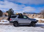
MODIFICATION: Attic Cargo Net
I really liked the idea of keeping lightweight gear up above the headline and out of the way (blankets, jackets, pillows, kids toys, etc.) It freed room in the cab and made use of a space that's often wasted. It features a double flap w/ hook to keep things sandwiched and secure. The second cord helps support my fishing rods.

It's outside the view of the rear view mirror and does not obstruct my view, even when loaded.

IMG_20170411_192119664.jpg

DURATION: <1hr

COST: <$10

HOW-TO:
I had an old cargo net from my old Audi A4 lying around that was the perfect size when stretched taught. Couple that with some bungee cord (purchased by the inch) and hooks from ACE Hardware, this was a bang for the buck storage mod. Use the cord to create a tight frame for the cargo net and use the hooks to mount to the grab handles. Beats paying big $$$ for attic storage found on BlueRidge or similar.
 
Last edited:

Sal R.

Active member
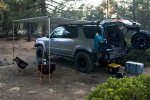
MODIFICATION: Auxilary Power Tray and Relay Bus

GOAL:

Add more accessories and keep the wiring clean.

PURPOSE:
With the air lockers and compressor install, I wanted to keep all the wiring clean with room for growth for the potential addition of aux lighting, CB, winch, etc. After reading numerous threads on aux power trays on TW and T4R, it was time to lay down the skeleton for the wiring schema.

Generally speaking, this is what I came up with:
wiring-general.jpg
The idea was to:
  • Minimize the wiring penetration from the engine compartment to the cockpit.
  • Keep all the load bearing wiring in the engine compartment.
  • Keep only the signal bearing wiring in the cockpit for electical safety.
  • Make it easy to add new switched accessories.
I used relays to accomplish the above requirements.

DURATION: 10-12 hours

MATERIALS:
16ga Steel Sheet Metal
Welder
Blue Sea 12 Circuit Fuse Block
Generic 6-Relay Bus Box
100A Type III Circuit Breaker
4ga Wiring w/ Terminals
16-18ga Wiring w/ Terminals
Female Spade Connectors
Add-A-Circuit Fuse Holder
12-Pin Molex Connector

COST: ~$120

HOW-TO:
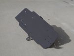
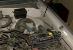
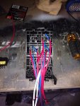
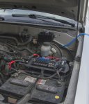
First thing was I made a power tray to hold the 100A circuit breaker, Blue Sea fuse box, and (finally) Alpine amplifier inline fuse. The fuse box is pretty big and there wasn't a whole lot of areas to mount it cleanly.

switchpanel02.JPG

Unfortunately, there is no template. I cut and shaped the 16ga sheet metal in place. Measured and cut the bracket legs in place. The welded tray assembly is mounted on the battery bracket support, inner fender, lower inner fender directly below the brake fluid resovoir, and loosely on top of the factory fuse box.

Power tray and relay bus box mounted and ready for wiring:
switchpanel03.JPG

Wiring schema for the switches:
wiring-switches.jpg

I changed the rear locker "on" schema (vs. ARB's). Originally, the rear locker "on" indicator would not illuminate unless the air compressor was turned "on" first. I did not like this concept because I would not know that the rear locker is set to engage until the air compressor was turned "on." Because my switches are mounted low, the hazard is I'm cruising along, the air compressor is accidentally turned on and the rear switch was, unknowingly, also turned on and the rear locks, unintentionally. As a result, I'd like to know immediately on ignition if the rear lockers are set to engage when the compressor is activated.

For the ignition 12V, I used the low amp heater system fuse. To be safe, I wanted to tap a low amperage (relatively speaking) non-critical system.

Wiring it all up:
Relay bus:
relaybox.jpg

Wiring Blue Sea fuse box:
switchpanel06.JPG

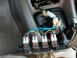
Wires labelled and wiring up center console (on point!):
switchpanel05.JPG

For my switches, I used OTRATTW Contura XIV switches, Lower Independant, Daylight Green/Red combo. I used OEM bezel console, part number: 588440-C010, to hold them.

The switch panel terminates at the Molex connector so the panel can be removed, if necessary. Pretty clean IMO.

Finished!
switchpanel08.JPG
switchpanel04.JPG

Fired it up and it all worked on the first try!

It pays to plan ahead.
 

Sal R.

Active member
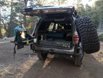
MODIFICATION: Front And Rear Quick Disconnect Swaybar Links

GOAL:
Spend the least amount of time possible messing around w/ the factory swaybar links.

PURPOSE:
I, generally, removed the swaybar link when I'm off-road. I never liked the idea of a loose component free to impact something while the suspension is articulating. Most folks just disconnect and zip tie it, but that just wasn't for me. If you've ever disco'ed the links, then I'd wager that you realize that they can be a pain fidgeting around with a ratched AND and allen wrench. Thanks to jimsmola, this forum, and WabFab, quick disconnects are now available for consumption.

MATERIALS:
WabFab quickdisconnects front & rear

DURATION: 2 hours

COST: $265

HOW-TO:
The install is pretty straight forward. Although, when the links arrived, it did have a lot of excess length, which makes sense, since it allows you to tailor the lengths to your specific ride height. For my application, I opted to set a length just slightly shorter than OEM. I have found that this actually kept my ride tighter and responsive around town and less likely to induce the VSC when taking turns at high speeds.

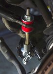
Front:
disco01.JPG

Rear:
disco02.JPG

Remove 2 nuts and pull 6 pins and I'm ready to party.

So, how much time did I actually save w/ the disco's?

Before I started the link install, I timed myself how long it actually took to exit the vehicle, go to the back, grab tools, and get to work.

After the links were dialed it, I timed myself using the same process.

Before: 27mins
After: 6mins.

And I haven't even trimmed off the excess length of the front links yet.

Awesome blossom.
 

Sal R.

Active member
MODIFICATION: T4R 13.3" Big Brake Upgrade

GOAL:
Replace the crappy OEM brakes with rotors and calipers from an 07 T4R Sport Edition that comes w/ 231mm 13WH calipers and (drum roll please) 338mm (13.3") rotors.

PURPOSE:
Pretty self explantory here. The OEM brakes...are ********. And mine were due for an overhaul. I had originally planned on doing the updated calipers for Tundra/Sequoias, but thanks to Scotty of Addicted Off-Road who pioneered this mod (AFAIK), this was a better investment of my time and money.

MATERIALS:
2007 T4R 13WH Brake Calipers
2007 T4R 338mm Brake Rotors
2007 T4R Brake Pads
Brake Fluid

DURATION: 8 hours

COST: $380

HOW-TO:
Scotty had a great, detailed write-up over at Expo. This post just expands on it with pictures. Everyone loves pictures, right?

First and foremost, all the hardware bolts on. The caveat is that you have to clearance the calipers, dust shield, and brake line. And these brakes are BIG. To stuff this, minimum 17" wheel is required and even then, it will depend wheel style, offset, and backspacing to clear the caliper.

My wheel choice yielded <3/4" between the caliper and inner rim and ~1/2" from the wheel spokes.

Before tearing into the brake system, I placed a wheel face down, placed the 338mm rotor into the wheel with caliper location mocked up to check clearances.

I assume you know how to do brake work, so I'm going to skip to the good stuff.

First, let's highlight the differences (aside from the caliper).

Before vs. After
t4rbrakes_07.JPG

Caliper Flange Mount Thickness OEM vs. T4R 13WH
As you can see, the OEM flange is thicker by about 1/8".
t4rbrakes_01.JPG

Rotor Diameter:
The rotor sports the 6x139.7 bolt circle and is of similar dimension to OEM.
t4rbrakes_04.JPG

t4rbrakes_06.JPG

Things you'll need to trim:
Dust shield (red):
t4rbrakes_05.JPG

You'll also have to bend the shield back about 1/8". Otherwise, the rotor will make contact.

T4R Caliper:
After vs. Before (lol)
t4rbrakes_09.JPG

Basically, you need to grind down the "pad" on the T4R caliper flange to sit flush w/ the rest of the flange. It's ~1/16" thick. I accomplished this by using a sharpie to mark the desired depth on the flange and grinded away using an angle grinder until all the shapie markings were gone. I, then, took a file to create a flat mounting surface.
t4rbrakes_11.JPG

Additionally, I had to clearance the inner ears of the caliper to make room for the rotor (red). Compared to OEM, the T4R caliper is offset towards the inside of the sequoia. Grinded off ~<1/8" using a dremel w/ grinder attachment.
t4rbrakes_12.JPG

Took me <10mins per caliper. Just make smooth, light passes. It's easier than it looks/sounds.

Bolted up to check for any more interferences:
Because the mounting flange is thinner than OEM, you'll find that the OEM mounting bolts will stick out past the spindle/steering knuckle mounting point. This is no cause for concern since there is adequate clearance from the rotor.
t4rbrakes_08.JPG

You can reuse the OEM hardline.

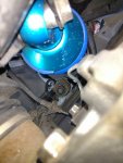
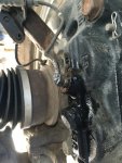
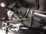
WARNING! The way the brake hardline mounts to the T4R caliper, it comes dangerously close to hitting the coil at full steering lock, even at static ride height. I had to carefully bend and shape the hard line as close to the brake assembly to provide adequate clearance. I would suggest replacing the hardline w/ an aftermarket braided assembly that terminates to a banjo bolt.

For my setup, even with the hard line routed for clearance at static ride height, my COs will make contact w/ the hardline at full stuff with the steering locked. I will be replacing that hardline at a later time. For now, it clears while cruising around town.

All buttoned up:
t4rbrakes_10.JPG

REMINDER: Bleed your brakes, lol.

Can't really give a before/after stopping distance comparison, but I can say this: Getting on the brakes will peel me out of my seat. And it certainly "feels" like it's stopping sooner. I am definitely getting more nose dive and recoil oscillation now.
 
Last edited:
Sal R.

Active member
MODIFICATION: Stainless Steel Braided Brakelines

GOAL:
Improve brake responsiveness and feel using stainless steel braided brakelines and increase clearance between front caliper and coilover suspension.

PURPOSE:
It is well documented that 13WL caliper upgrades that use the factory caliper hardline on 1st gen Tundras/Sequoias have issues clearing some coil/strut assemblies at full steering lock when the suspension is fully compressed. With the 13WH caliper offset inwards coupled with a larger mounting radius, clearance from the strut is further reduced, even at static ride height.

This (view looking up from caliper with steering wheel hard over)...
ss01.jpg

...can easily turn to this...
A7ECB7A5-3B19-42A7-8F60-B46A8BCF823D.jpg

...when the suspension cycles. Naturally, a lower profile solution is required. This led me to Crown Performance, who custom made sleeved stainless steel braided brakelines for 1st Gen Sequoias. Since I was already having the fronts made, I opted to have the rears measured and extended, as well. Crown had a lot of options for sleeving (colors and thickness) to help protect the braided lines. I chose the smoke since it was aesthetic and, more importantly, twice as thick compared to the colored vinyl they also had in stock.

MATERIALS:
Crown Performance Stainless Steel Brakelines, Front & Rear
Brake Fluid

DURATION: 3 hours

COST: $110

HOW-TO:
Remove OEM line and replace w/ the new.
Bleed brakes.

Nothing special or out-of-the-ordinary regarding the brakelines.

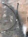
For my requirements, I had requested the front lines extended +2" over stock and terminate to a banjo fitting to reduce the profile of the brakeline where it attaches to the caliper. It is made as a single piece from the frame to the caliper, as opposed to OEM, which comes in two pieces.

Old vs. New
ss03.jpg

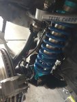
Installed:
ss02.jpg

As you can see it's routed close to the brake assembly away from the coilovers to provide maximum clearance.

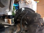
For the rear lines, I opted to keep the factory hardline on the axle to help keep costs down. The new stainless steel brakelines only replace the factory rubber components from the body to the axle housing and the units on the rear calipers.

Old vs. New
ss04.jpg

Installed:
2017-05-26 12_36_43.jpg

2017-05-26 12_36_07.jpg

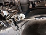
I don't know what possessed toyota to change the mounting schema of the passenger side rear brakeline, but instead of a clip, it's held in place using a bolt and an specialized integrated bracket on the rubber hose itself:
2017-05-26 12_36_16.jpg

So, included with the kit is a bracket with shim stacks and clamp down circlip. Doesn't exactly fit in the OEM location, but it's tight and won't be going anywhere.

The pedal feel is noticeably firm. It's on par w/ my lexus RX350. Getting on the brakes is definitely jarring and more responsive. It is a welcome change. I do not feel I have smash on the brakes just to slow to a stop.
 

Sal R.

Active member
MODIFICATION: Tailgate Molle Panel Storage System

GOAL:
Add an easily-accessible, modular, molle storage system on the hatch tailgate.

PURPOSE:
You would think that with all the ample room in the sequoia and the addition of the cargo box, I'd be content w/ my storage options. Well, you thought wrong, mister. I'm a fan of utilizing space efficiently. While the cargo box was a huge plus, getting to it can be a bit of a pain. I wanted an easy-access solution w/o having to lift the hatch for things like First Aid Kit, air hose, tire deflators, etc. The solution came in the form of a molle system mounted on the tailgate. With the rear window down, which is generally the case when I'm out and about, I could quickly access molle pouches w/ gear in it.

MATERIALS:
Grey Man Tactical Rigid Insert Panels - MOLLE (RIP-M) 15" x 25.75" x2
Misc Nylon spacers 1/4" & 1/2" thick
Misc nuts and bolts

DURATION: 2 hours

COST: $150

HOW-TO:
Grey Man has a lot of options for RIP-M sizes. I opted to get two of the above to fully cover the tailgate. The RIP-M panel is made of a type of polyethylene. Meaning, it's lightweight (@26oz) compared to metal MOLLE panels. Considering that this is being mounted on an overhead door propped up using gas struts, keeping the assembly and all hanging gear weight efficient was key.

The install is simple. I assume you know how to remove the rear panel cover. If not, look a few posts back regarding adding a remote rear window switch.

Steps:
  1. Remove tailgate panel
  2. Layout RIP-M panels and tape them down
  3. Drill holes
  4. Assemble
  5. Put everything back together
When I laid out the MOLLE panels, I chose to mount it as high on the tailgate as possible w/o creating any interferance. The reason for this is to minimize the added moment applied to the rear hatch door as a result of the added weight while in the open position. By minimizing the applied moment, you reduce the risk of the door sagging due to the weight of the stuff planned to be hung on the door.

What is the max weight limit of gear on the door? About 30lbs with the ladder.

IMG_20180730_104413.jpg

I used the nylon spacers to create a space between the rear panel and the RIP-M. 1/4" spacers on the top and outer holes of the RIP-M and the 1/2" spacers in the lower and inner edges of the RIP-M. Without the spacers, you would not be able to slide the MOLLE straps thru the RIP-M while mounted on the rear panel. You could choose a spacing of your own specifications. I like to keep things tight and minimal profile.

IMG_20170613_121737.jpg

So what do I have on my rear panel?
  • ARB OBA air hose
  • ARB tire deflator w/ gauge
  • Hatch window cover
  • Nitrile gloves (lots of them)
  • Survival knife
  • Assorted straps, zip-ties, & bungee cords
  • Misc ratchet tie-downs
  • Umbrella
  • Fuel siphon hose
I do have to "push" to get maximum extension out of the hatch. I'm guessing it's because the struts are OE, tired and needs replacement. I've always had to do that, but moreso after the addition of the MOLLE panel and gear. However, once up, the door stays up.

With the rear window down, accessing the FAK and air kit is a breeze, which was really the main priority of this system.

A place for everything and everything in its place.

Now to figure something out for the rearmost DS/PS windows...
 
Last edited:
Sal R.

Active member
MODIFICATION: Custom Rear Hatch Ladder

GOAL:
Make accessing the roof easier.

PURPOSE:
Nothing spells overland like a rear hatch ladder. But seriously speaking, accessing the roof was a pain. Especially when I have to get up there to add/remove brackets for luggage, snowboard rack, quickfists for shovels, etc. After GOBI customer service failed me, I got my money back and took it upon myself to build a ladder. Seemed simple enough, right? There were other factors other than crappy customer service. I was always concerned w/ the location of the GOBI ladder, fitment w/ the rear wing, and more often than not, it wasn't always plumb. With a custom ladder, I could mount it however I wanted it.

MATERIALS:
1" outer diamter PVC pipes + misc fittings
1" outer diameter tube stock, 17ft.
16ga metal sheet 12"x18"
10ga metal sheet 12"x18"
Misc bolts
Weatherproof double sided tape
Weatherstripping

DURATION: 20 hours

COST: $60

HOW-TO:
Normally, I'd take a lot of pictures, but this time, not so much. Honestly, I didn't think this was going to work, since this is my first real fabrication job and it was a real learning experience. I figured if it didn't work out, I lost out on the cost of some material and labor. I just kinda went along with it and built it in place and reworked things that didn't work.

Rough Steps:
  1. Mockup a ladder using the PVC tubing
  2. Bend steel tubes to match
  3. Bend/Cut sheet metal to make upper and lower attachment brackets
  4. Weld bracket
  5. Drill and tap for attachment hardware
  6. Weld tube to sheet metal brackets
  7. Weld tube steps to ladder
  8. Paint

Here's the initial fitment:
IMG_20170724_080547921_HDR.jpg

IMG_20170724_080727157_HDR.jpg

Initally, the upper mount was a 16ga bracket bent up from the hatch edge to meet the ladder bracket. The bracket is held in place using doube sided tape and it grabbed the edge of the upper hatch door. That didn't work. As you can see in the pic, the 16ga bracket sagged with the weight of the ladder and made contact with the rear wing. The pic was taken a day after I mounted everything up and I had put my weight on it.

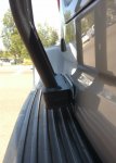
Additionally, I had used the cheapest PVC tubing to mock up the ladder (to keep cost down). This was a mistake. It was not stiff enough to be used as a real template. As a result, my ladder welded together was 1/2" shorter than expected since the steel tube did not flex like the PVC mock up. Instead of using 1x ABS filler spacer on the bottom mount, I had to use 2x. The spacer was built in so I could fine tune the ladder height to suit my preferences. Although I did not expect to use 1" worth of filler just to make the ladder work.

My revised mount mock-up:
IMG_20170729_104809745.jpg

IMG_20170729_104820456.jpg

IMG_20170729_104755370.jpg

I reworked the bracket so that instead of bending upward, it sits flush w/ the hatch outer mold line (OML) still grabbing the edge of the upper door. For now, I'm using threaded stand-offs to figure out how much height I need to properly secure the upper ladder. Once I'm sure that it is right, I'll cut off the existing brackets on the ladder side and weld new brackets that have an extended length downward to meet the hatch bracket on the hatch OML. Instead of a floating type mount I was previously using, the weight of the ladder will rest on the hatch. I want to make sure this time it's right because bending 10ga sheet metal by hand is not fun.

Additionally, the upper bracket is tapered towards the door edge so that the ladder could be mounted as far left as possible. The limiting structure is the rear hatch door hinge. I could have slotted the bracket, but I did not want to sacrifice its ability to hold onto the ladder and the weight.

In hindsight, I should have bent tubes downward to rest on the hatch, but I'll make due with with what I've got since I don't want to pay more money to have tubes bent. Not to mention graft on the new pieces, shape, blend them together, and refinish the whole thing again.

The lower mount is secured to the hatch using clamping method on the lower hatch door edge. The clamping force uses a welded bracket assembly plus some hardware. The lower mount is intended to keep the ladder in place and not meant to take vertical load. All the load is meant to be taken by the upper mounts.
 
Last edited:
Sal R.

Active member
2017-08-003.jpg

Despite all the vigilance and care regarding the maintenance of the lower ball joints, I still fall victim to a failed lower ball joint (LBJ).

IMG_20170803_101247.jpg

These were "OEM" LBJs purchased from eBay, installed 3 months ago, with less than 5k miles on them, zero miles off road. The slug that bolts into the lower control arm completely sheared from the ball joint and housing.

Luckily for me, the ball joint sheared while pulling out of a parking spot and not while driving on the highway. Additionally, luck was still on my side. A shop 2 miles away from where I was stranded could get replacement parts and have me back on the road the same day. All in all, the cow walked away from a potentially catastrophic failure with just a misshapen fender. Lucky, indeed.

In the days prior to this failure, I was getting a very loud audible squeaking/groaning from under the car that was not dependent on the steering. I thought it was my steering rack going. I never thought it could have been the ball joints.

One thing to note. After the installation of these ball joints, the steering was notably stiffer. More resistant to turning than the previous pair.

With the replacements in, my front is quiet again...save except some groans from the Total Chaos upper control arms complaining to be rebuilt.

Lesson: Buy only genuine Toyota parts from Toyota dealers. Don't ignore squeaks from the front end.
 

Sal R.

Active member
MODIFICATION: Rear Window Cover/Molle Storage

GOAL:
Make use of an, otherwise, wasted space.

PURPOSE:
While searching for methods to implement privacy coverings for the windows, I came across this image:
molle mount.jpg

I thought it was a heckuva idea. Seeing as I had a new welder that I wanted to play with, this was the ideal project. I would have liked to use a standard molle spec panel, but they don't exist for Sequoias (big surprise).

MATERIALS:
Display shelf
16ga sheet metal
Self-tapping screws
Paint stripper
Self-etching Primer
Paint

DURATION: 8 hours

COST: $20

HOW-TO:

Steps:
  1. Cut the shelf to appropriate dimensions to fit window recess
  2. Remove all trim pieces (can't get away from that and no way around it)
  3. Cut 16ga sheet metal into 1" strips
  4. Bend strips to contour window support surrounding body to make brackets
  5. Mockup brackets and mount it to the window sheet metal body
  6. Position shelf panel over mocked up brackets and mark the position where the shelf panel will be welded to the bracket
  7. Remove shelf panel
  8. Remove brackets
  9. Weld assembly together
  10. Check fitment by installing using self tapping screws
  11. Remove and re-finish
  12. Notch the trim pieces and put everything back together
This project was meant to be low cost. Most of the build materials I already had from previous projects. To start, I need some wire shelving. Scouring craiglist, I found a deal! A full shelf panel for $10 10 minutes away from where I live.

2017-06-14 16_29_05.jpg

So, I cut the panel to fit and then proceeded to remove the surrounding trim pieces to gain access to the window sheet metal body structure.
2017-07-30 09_51_01.jpg

Once exposed, I cut some strips, bent them to follow the shape of the surrounding window structure and mocked up the best locations for a mounting schema.
2017-07-30 12_27_04.jpg

Once I had the brackets positioned, I overlayed the shelf panel over the bracket extensions, marked where the brackets need to be welded to the panel and welded the assembly together.

The following pic is just after having welded 3 of 4 brackets and checking fitment with the excesses trimmed off.
2017-07-30 13_08_23.jpg

After completing the welded assembly, I cleaned the welds, stripped the paint to the bare metal, and refinished the panel using some self-etching primer and black paint. This part took the longest. I'd guess I spent a good 3-4 hours just stripping and cleaning the panel of all white paint. This was nasty stuff. I still have chemical burns on my arms where the stripper splash on me.

Here are some close up details of the shapes of the brackets...
2017-08-03 09_59_05.jpg

2017-08-03 09_59_11.jpg

After the finished panel was installed, I carefully notched the trim pieces to accept the new storage panel. I took my time with this part (2 hours) removing only the smallest necessary amount to able to remove/install at will.
2017-08-03 15_50_24.jpg

Cheers.
 
Last edited:

Forum statistics

Threads
188,342
Messages
2,905,812
Members
229,959
Latest member
bdpkauai
Top