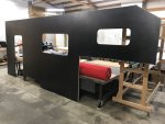
2022 Ford F550 - DIY - Adventure Expedition Vehicle Build Thread

Vance Vanz

Well-known member
The amazing work continues! Sorry if I missed it, how are you cutting the carbon cloth?
Hey Highwest! I hope you are doing well.

As always, thanks for your words of encouragement ?.

I started with these.
https://www.uscomposites.com/cutters.html (Top left of page, Cat No: WISS 101)
They worked well for a bit and then dulled pretty quick. I have tried to sharpen them twice, but I must be doing something wrong, or they must require a special sharpener. I can't get them sharp again, or to cut for a crap. Also, they create a weird pressure point on the top knuckle of my thumb and if I use them long enough, my thumb will start to go numb.

I then moved onto these:
https://www.homedepot.com/p/Wiss-10-in-Offset-Professional-Shear-CW10T/313485237
For the price and the length of time they have stayed sharp, you can't beat them for manual scissors. They also have a comfy/ergonomic grip compared to the ones above. I also use them on cardboard and a ton of other light duty materials.​

I then finally stopped being so cheap, way too late in the game, and bought these.
Why did I wait sooooo long to buy a pair of electric cutters ?☹??. These things are awesome! They cut quickly and amazingly cleanly. I was surprised how cleanly they cut not only carbon fiber cloth, but many other materials. They are my new best friend!​

If anyone is doing any kind of sizable fiberglass or carbon fiber job, PLEASE do yourself a favor and just buy a pair of electric cutters from the get go. I didn't, and I regret it; especially my numb thumb ?.
 

Vance Vanz

Well-known member
All the little details that eat up time.
Yeah Buddy!

Hey Alloy.

These past few days have felt like one huge time suck. Between the vent fan, skylight, AC unit, solar panels, surf board rack, rear ladder.................., I am up to my wazoo in details for the final roof layout. ?o_O it's a bit bonkers at times, especially since I'm also infusing all of the cut outs and any needed wire chases in the layup of my roof panel.
 

Victorian

Approved Vendor : Total Composites
I truly admire the efforts you are putting into this! Please keep us posted about the final weight. I'm very interested to see what difference the CF made.
 

Vance Vanz

Well-known member
Have you considered connecting these 2 mounts together?

View attachment 749265
Hey Alloy,

Yes. Let me answer this in two ways:

As far as connecting them together by welding something in between them, I decided not to for a couple of reasons. #1 EarthRoamer does not and #2 another build that I also modeled my three point subframe after did not. Also, there is the factory welded cross tube that ties the chassis rails together right in front of these.

They do technically get connected together when the camper is bolted to them and I don't mean with just a composite panel of carbon fiber skins and a core material (in my case also 1/2" marine grade plywood). I also have the two bars of flat stock steel laid up in my floor. They span the width of the camper, are placed over two bolts holes on each outrigger and are drilled/tapped.
 
Last edited:

Vance Vanz

Well-known member
I truly admire the efforts you are putting into this! Please keep us posted about the final weight. I'm very interested to see what difference the CF made.
Thanks Andreas :).

I sure hope I don't regret it in the end ?.

I will definitely be posting weights once I accumulate a few more.

I have a weight after the single rear wheel conversion was installed and after the subframe was completed. The third weight will be the addition of just the carbon fiber camper when it is all ready for paint/or it comes back from paint.
 

Alloy

Well-known member
Hey Alloy,

Yes. Let me answer this in two ways:

As far as connecting them together by welding something in between them, I decided not to for a couple of reasons. #1 EarthRoamer does not and #2 another build that I also modeled my three point subframe after did not. Also, there is the factory welded cross tube that ties the chassis rails together right in front of these.

They do technically get connected together when the camper is bolted to them and I don't mean with just a composite panel of carbon fiber skins and a core material (in my case also 1/2" marine grade plywood). I also have the two bars of flat stock steel laid up in my floor. They span the width of the camper, are placed over two bolts holes on each outrigger and are drilled/tapped.

yes I agree......but :) ......there is CYA benift to joining them together to make a solid beam that won't torque the chassis rails or deflect (bend) the flatbar.

How much wheel lift/ chassis twist did you allow for?
 

Vance Vanz

Well-known member
yes I agree......but :) ......there is CYA benift to joining them together to make a solid beam that won't torque the chassis rails or deflect (bend) the flatbar.

How much wheel lift/ chassis twist did you allow for?
Hey Alloy,

Agreed. It is the balance of maintaining flex in in the chassis frame (not wanting to over restrict it for off roading capability) while also ensuring there is no/not too much flex that is passed onto the composite camper. This is the balance I have struck with the overall design.

Iv'e see too many subframe designs that actually restrict the factory chassis too much because they don't want to design a subframe that actually allows for chassis flex.

It has worked for ER for many years and why I also shop and field flex tested everything many times. All that info is in the thread. Everything was tested at max wheel lift/flex both front and rear. The only factor that has not yet been tested is all of the previous testing with the camper on/build complete-at its dry and wet weight.

I'll do one last round of max lift/flex testing when everything is complete. If for some reason there is too much flex, just behind the factory cab/factory welded cross member, I can easily weld a plate to join them together.

I appreciate you looking out for these things and mentioning them.
 

Alloy

Well-known member
Hey Alloy,

Agreed. It is the balance of maintaining flex in in the chassis frame (not wanting to over restrict it for off roading capability) while also ensuring there is no/not too much flex that is passed onto the composite camper. This is the balance I have struck with the overall design.

Iv'e see too many subframe designs that actually restrict the factory chassis too much because they don't want to design a subframe that actually allows for chassis flex.

It has worked for ER for many years and why I also shop and field flex tested everything many times. All that info is in the thread. Everything was tested at max wheel lift/flex both front and rear. The only factor that has not yet been tested is all of the previous testing with the camper on/build complete-at its dry and wet weight.

I'll do one last round of max lift/flex testing when everything is complete. If for some reason there is too much flex, just behind the factory cab/factory welded cross member, I can easily weld a plate to join them together.

I appreciate you looking out for these things and mentioning them.

Chassis flex it good (except when there's an alum cab) but it shouldn't be transferred into the 2 mounts. .......it would be interesting to know if the chassis crossmember prevent (or how much) the front box mounts from moving on the XYZ axis.

The boxed (front) section of the chassis + cab restrict the movement ( to prevent the alum cab from cracking??) so the rear channel section must be doing most of the flexing.
 

Vance Vanz

Well-known member
Hi All,

Happy Thanksgiving! I’m a day late, maybe two, but who’s counting :geek:.

While you were baking a turkey, I was baking my roof panel ?.

It’s crazy to think that it has been a month since my last post. That thing called LIFE happened again and I lost two full weeks on the build. I’m glad to be back on the project and grinding away ?‍♂️.

I’ll pick up where I left off……….

The resin finally showed up, but a week and a half later than quoted. I love it when you pay out the wazoo for shipping and they can’t even get it to you within the conservative time estimates they give you.

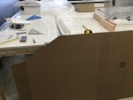
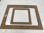
I finalized the roof layout and created the vent fan, AC unit and skylight cut out templates while waiting for the resin. I also checked/laid out the angles, clearances, aesthetics and wind flow of the cab over roof angle to the skylight spoiler and skylight.
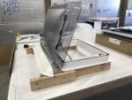
IMG_8076.jpegIMG_8075.jpegIMG_8074.jpeg

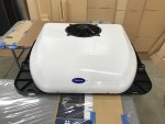
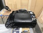
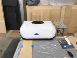
I'll get into more info, details and pics when it is finalized, but I also did some modifications to the A/C unit while creating the cut out template for the roof panel. This 12V A/C unit is one of the most efficient, quietest, lightest and lowest height profiles for its BTUH rating and the price point is almost half the cost of other comparable 12V rooftop units, $2,500 vs $4,500-5,000. This is all GREAT as Mabru got its start in the marine A/C industry and is looking to enter the RV A/C market. BUT, the problem is they still have to refine their design of the installation of this unit and the supply/return grill assembly is big and ugly. They want you to cut SIX separate holes in the roof (supply/return opening, electrical penetration, and four mounting holes) to install this thing, as opposed to having everything come through one 14 x 14 opening like many other rooftop A/C unit manufactures.

I'm going to do custom supply registers in the ceiling headliner and run a common return ceiling (I won't have a visible return grill), so I didn't care about the ugly supply/return grill-I was going to toss it anyway. As far as the six penetrations in the roof, I knew I could re-route the electrical through the supply/return opening and I was hoping I could remount the four main mounting bolts to also come through the supply/return penetration. Unfortunately, I could not remount the four main mounting bolts to sit inside the supply/return opening, so I will have have to drill four holes for the mounting bolts. Not a huge deal, as their gasket takes care of all of this, but the less penetrations the better.

I also decided to do two smaller cutouts in the roof for the supply and return, as opposed to one larger cutout. This left more material, therefor structural support, in my roof and will also make it easier to create/install a custom foam boot that will be needed to separate the supply air from the return air in the head liner/common return ceiling. (You will see a picture of this in the roof panel layup post to come.)

The other quirky thing is the plastic baseplate for the unit sticks out further than the top cover, so I cut it back and shaped it to match the lid. I spoke with the MFG's RV A/C department about all of these modifications and they said they know, they're considering them for the next model.
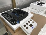
IMG_8095.jpegIMG_8080.jpegIMG_8088.jpegIMG_8094.jpegIMG_8090.jpegIMG_8096.jpeg

These were all little modifications I was willing to do/tolerate given this things specs and price point.
 

Vance Vanz

Well-known member
Resin Infusion – Passenger’s Sidewall Panel – Layup & Infusion

Three layers of CF, core and another three layers of CF. Spray tacked the inserts for the entry door frame. Wrapped the door and window cut outs with two layers of CF.
IMG_8105.jpegIMG_8103.jpegIMG_8108.jpegIMG_8109.jpegIMG_8107.jpeg

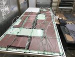
Consumables were the same as the last sidewall panel, just a variation in the spiral supply tubing layout because of the door cut out. I also reduced the number of supply feed lines (previously mentioned as an option on the last sidewall layup).
IMG_8110.jpeg

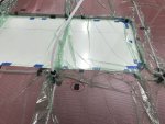
What is this; that pesky little RED CIRCLE?
IMG_8112.jpeg
?Leak!, where ?? Here little leaky, leaky........, where are you little leaky, leaky? ?........, ?.........?! OK little leaky, leaky,....... I'm going to FIIIIIIIIIND YOOOOOU ??!!!!

This is GETTING OLD Leaky, Leaky...........?☹??. This is getting REALLY OLD Leaky Leaky..........??. Time for a break and a snack..................., so I don't kill you Leaky, Leaky ?.

Oh, there you are Leaky, Leaky ??. How did you get nicked with a microscopic hole that only a person with Aerokinetic hearing could find you?

Finally time for infusion ?:
IMG_8113.jpeg
 

Vance Vanz

Well-known member
Resin Infusion – Passenger’s Sidewall Panel – Lay Up (Continued......)

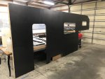
The Final Product - 18'-2 5/8" L x 7'-1" H Sidewall Panel

Peel Ply Side:
IMG_8120.jpegIMG_8121.jpeg

Layup Table Side:
IMG_8123.jpegIMG_8124.jpegIMG_8119.jpeg

Everything came out similar to the finish of the last sidewall panel.

Technical info from the layup for those that are interested:
  • 6 gallons of epoxy was used for the layup
  • Infusion time was about 2 hour and 55 minutes. (Note: At first I had the shop thermostat set at 65, but the resin was at about 60, so the layup was not flowing very well. I cranked the shop heat up to 77 and installed a piece of plastic over the layup table with a space heater under the plastic and everything started flowing as usual. Mental not for next time, don't forget to turn the heat up silly.)
 

Vance Vanz

Well-known member
Pass Through - Initial Thoughts & Layout

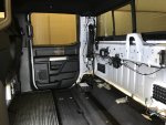
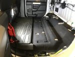
It was time to yank everything out of the crew cab and decide what my final pass through dimensions would be, largely based upon what seat arrangement I decided to go with.
IMG_8137.jpegIMG_8139.jpegIMG_8143.jpeg

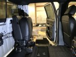
There are basically two seat options for the crew cab, or two that I am considering, two 40 bench seats, or two front bucket seats. The factory 40 bench seat sits on the passenger side and the 60 seat on the driver side. Unfortunately the feet on the passenger side 40 seat would not mount directly to the mounting bolts/studs on the driver side for the 60 seat. So.............., I put the feet from the 60 seat on the 40 seat and three of the four mounting holes lined right up with the factory mounting bolts/studs. That pretty much made up my mind as far as which seats I will go with in the crew cab. Two 40 seats also gives you a wider pass through area than two front bucket seats. Front bucket seats would also require installing all new non factory studs for mounting and the seats would also cost a lot more than 40's.

This was the easy part. Now I will need to buy a used 40 seat and basically use everything off of the new 60 seat, feet, back locking latch, seat belt latch, upholstery, etc to get the used 40 seat looking and functioning exactly like a brand new factory driver's side 40 seat. It will not be easy, but it will be worth it.
IMG_8131.jpegIMG_8135.jpeg

I will also have to remount the factory subwoofer in a custom made box and remount the amp. Pulling the rear sliding window out, hopefully without breaking it, is also going to be a blast. For now I have decided to leave the floor storage box in and integrate the pass through platform into it/with it.

This should give me a pass through that is 18-3/4" wide by 35" tall. I will also be making a custom composite insulated/lockable/removable door for the pass through.

I will share more detailed info and pics as this all progresses. For now, the seats and pass through size where the two most important things to figure out so I can build/finish the front wall on the camper.

If anyone has already done one of these and made it look as if it were factory, I'm all ears for any info, recommendations, pinch points, etc.
 
Last edited:

Vance Vanz

Well-known member
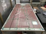
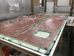
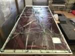
Resin Infusion – Roof Panel – Layup & Infusion

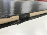
Three layers of CF, foam core and another three layers of CF. I wrapped all of the cut outs with four layers of CF, the 8.85oz biaxial and 5.7oz 2x2 twill from each side of the skin.

Dry fitted and ready for consumables:
IMG_8146.jpeg

Consumables applied and ready for infusion:
IMG_8150.jpegIMG_8151.jpeg

No SNEAKY LEAKY on this one ????!

Infusion complete, cured and ready for messy time:
IMG_8152.jpeg

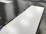
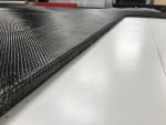
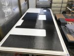
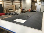
The Final Product - 17'-1/8" L x 7'-6" W Roof Panel

Peel Ply Side:
IMG_8155.jpegIMG_8156.jpeg

Layup Table Side:
IMG_8157.jpegIMG_8158.jpeg

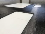
Cut Outs:
IMG_8160.jpegIMG_8161.jpeg

Technical info from the layup for those that are interested:
  • 7.875 gallons of epoxy was used for the layup
  • Infusion time was about 2 hour and 35 minutes.
I'm so used to seeing these panels on the layup table, so they don't look all that big. It isn't until I have to move these things around the shop and see them standing/sitting by themselves that I realize how freaking huge these panels are. This Camper shell is going to be MASSIVE.
 

Forum statistics

Threads
188,026
Messages
2,901,329
Members
229,411
Latest member
IvaBru
Top