4307's Canadian Taco Build

4307

Adventurer
G-Day! :D

I'm 4307 and this is my Canadian flavored Taco. :26_7_2:

The purpose of my build.... " head for the bush! " Overland style.

The project is a Silver, 2004, D-Cab, TRD. Bought it off the lot, new. Actually it was one of three last, new, late 04 D-Cabs available in Canada, before the 05 model change.

I've been lurking in the shadows of Expedition Portal for some time now and occasionally occupy a corner in TTORA land.

I've been driving the truck with stock suspension since day one. I'm a cheap ***. I chose to drive the truck, stock, off road and push it's limits. So far I'm very impressed, errrr! Except for the BFG Rugged trails! They are, what they are! Oh did I mention I was a cheap ***?
Anyway, the real reason it's still stock is budget. I feel more comfortable paying down 3/4's of the payments and keep the Kilometers down to a realistic level until I get the missing parts for the suspension, gears, tires. (sitting @ 55,000km right now).

Before the truck purchase, I've been buying tools, building up a home fab shop (in the basement). Tool shop is my other, other hobby. Now I have the main tools. Its time to build. Building is half the fun for me.

O.K. the cheap *** thing isn't totally true. I'm actually sitting on a pile-O-parts. There's a few goodies in the pile. I'm cheap for not putting them on yet.

ARB bull bar
Donahoe Coilovers
63' Chevy leaf springs ( junkyard specials.... rebuilt them, post to come)
255/ 75R16 Maxxis Bighorns
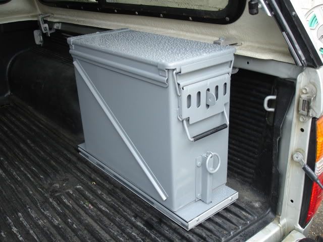
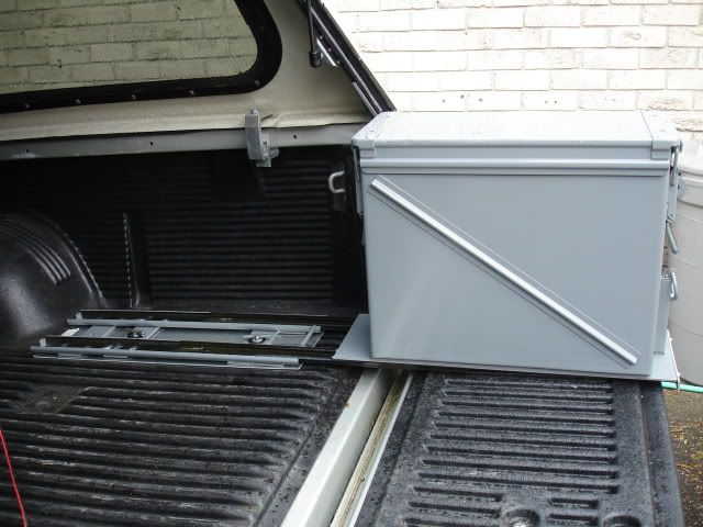
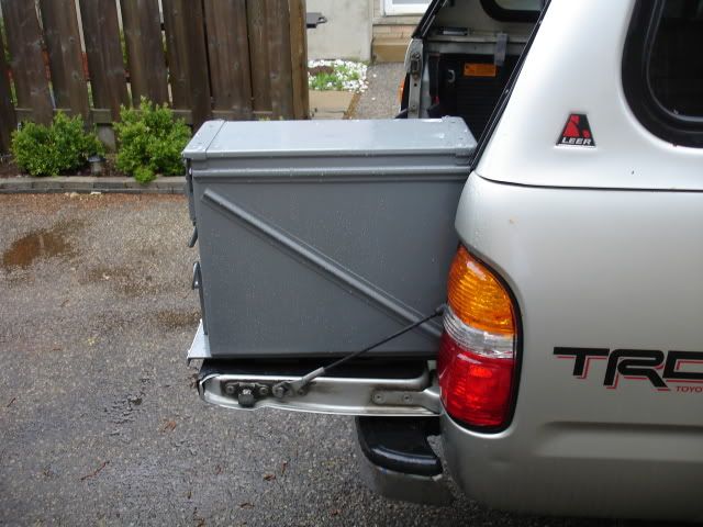
Ammo can on drawer slide.... Page 1, post # 2 - 7
Leer canopy.
Thule roof rack on the Leer cap
Yakima roof rack over the double cab.
Custom rear bumper.... Page 1-3... post # 8 and counting...
Hi-lift jack and shovel
KEW 8000 budget winch ($300 Cdn). Identical to the Mile Marker PE 8000. If it saves my *** a few times it payed for it's self. We'll see how it holds up.
Xantrex Xpower 1200 power inverter.
Blue Sea fuse box
ARB air compressor
8- 5'' rubber sealed tractor lights. Future rock lights.
A couple of 12v remote control modules. hehehe.... this is pretty cool!
Optima Yellow top. (I've been using it quite a bit as a stand alone, recharging on a charger. Great battery it will be installed in the truck, dual battery.)
Sure Power Battery Isolator
12v lights - for the interior of my truck cap and rear roof rack bar.
Uniden PRO 520 XL CB radio (future home... the ash tray)
K 40 antenna
in cab power inverter.
Cheap rear view camera. hmmm.... should be interesting, Cheapness!
Garmin 60c GPS
Mac GPS Pro software - for Garmin controlled moving map software, Ontario maps @ the moment. Running this on a Mac 17'' Powerbook, a little big for wheeling, but great to look at with the help of a co-pilot (Still in negotiations. Oh Dear can you....)

Other pile-o-parts for a distant future project....
Dana 44 front Wagoneer shop ornament.
K- 10 brakes, calipers
O.K. I have half the parts for a SAS project. I don't want to think of that right now, it's not in my current budget.

Anyway. This coming spring my truck will see the bulk of the transformation. I still need some parts.

This summer I was able to do some fabrication. My free time went to fabricating instead of traveling. Thats O.K. there is always next year.

Here is a pic of my truck the day after I bought it....
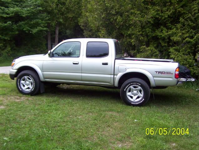
LastNew04DCinCanada.jpg


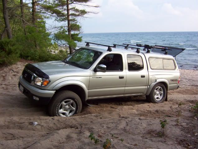
At the beach.....

SAND.jpg


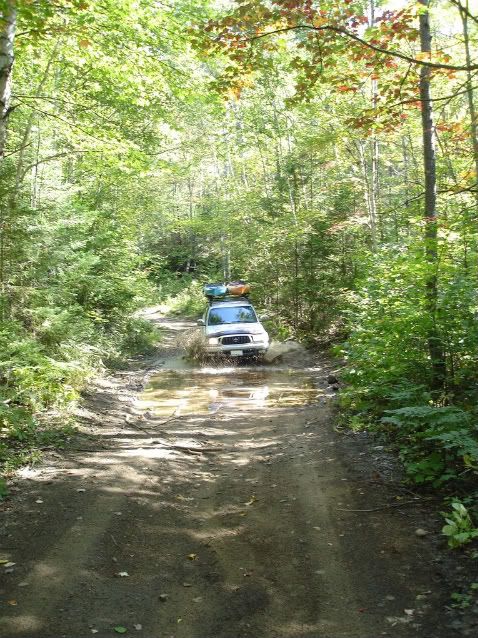
Dorset Ontario....

Sherborne4.jpg


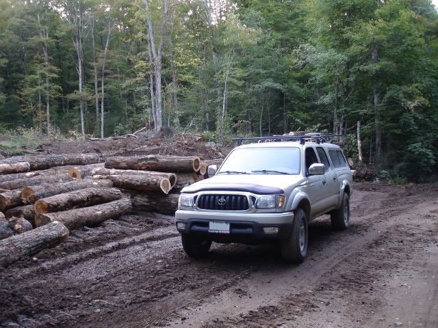
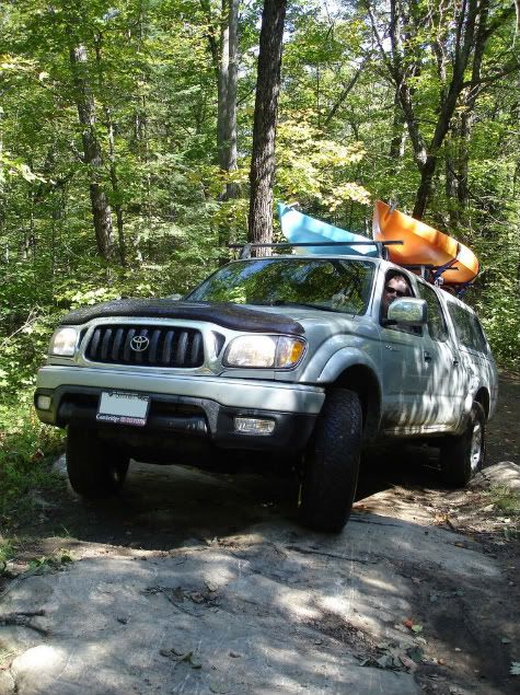
TACO2.jpg


TACO1.jpg


It's still great to get away in a Stock-o Taco.
I can't wait until spring, too glue all this stuff on.
I wish I had a garage, so I can work on the truck during the winter. Oh well. I'll live!


I'll be posting all my builds as mega posts :sombrero: . I hope thats cool with everyone. :D The posts will be step by step format with pics....

Completed projects will have page #'s beside the above mod's list to guide people to the start - finish of the project build, that way the build for particular projects are easier to find. Other wise, it would be a complete pain to flip through every confusing page to find a particular build.
I hope this will make it easier for Expedition portal members.
I will also post my build links from TTORA, so people can view all the questions and comments, good and bad.

If you have questions for me, post in these threads or P.M. me, I'll answer then as soon as I can.
 
Last edited:

4307

Adventurer
Ammo can drawer slide build....

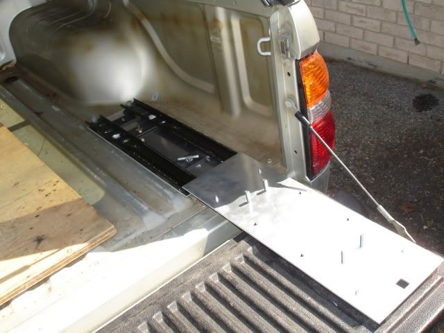
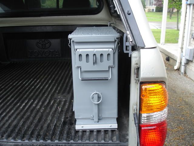
Here's a project I finished.... the ammo can drawer slide.
This was posted a while back in the fabrication section on TTORA forums.

The idea came to me while sitting on the thrown... go figure.

The project was less than $70 including the ammo can.
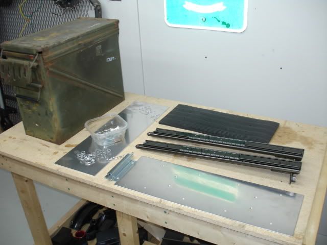
the parts include surplus ammo can, filing cabinet drawer slides, 2 aluminum mounting plates, nuts, bolts, machine screws, magnet, fence latch assembly, loctite, Duplicolor battleship gray paint, primer, workshop foam floor mat, scrap steel.

I was going to simply bolt the ammo can directly to the truck bed, but..... I had to take it to the next level.

The ammo can will hold tools, recovery gear, tire repair kit, roof rack straps and some other junk. I used a plastic tool box for all that gear but the plastic box was cracking. The reason I put the ammo box on slides was.... I hate climbing into the back of the truck to retrieve items I use on a regular basis like roof rack straps this will save my back.

Here's a sequence of the build....

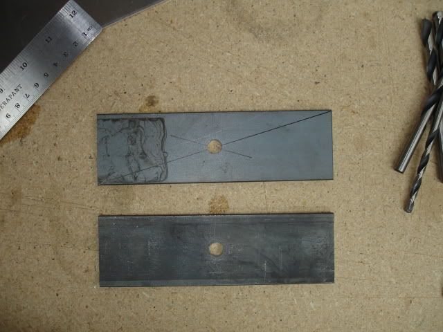
The parts:

DSC02682.jpg


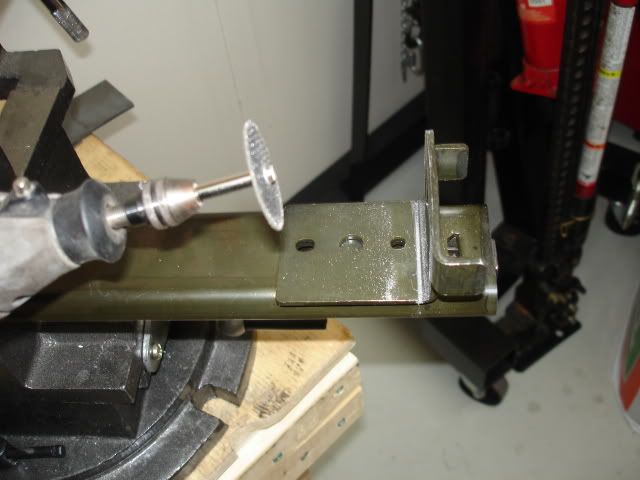
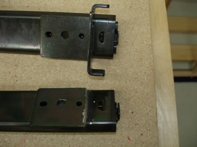
The slides need modification:

DSC02686.jpg


DSC02687.jpg


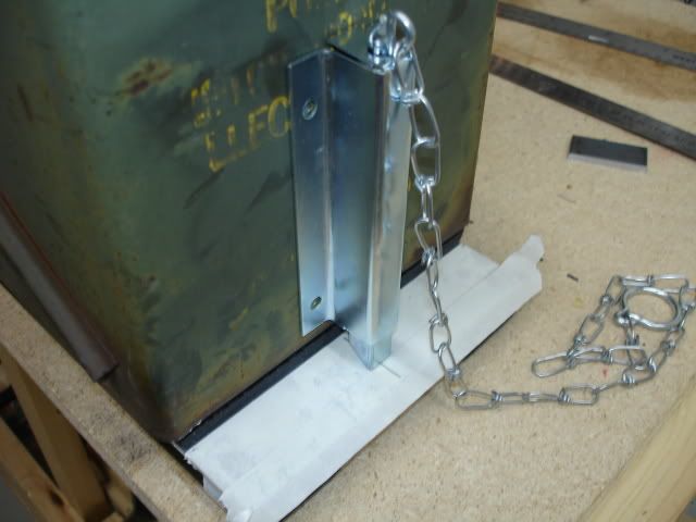
After drilling the holes on the top plate of the slide, I positioned the fence latch in position to figure out how it will work:

DSC02691.jpg


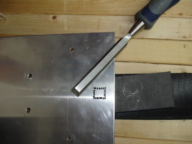
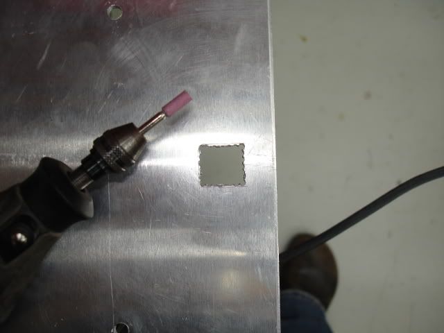
After I was confident the latch position was in the correct place, I drilled perforation holes for the latch hole. I used a chisel to punch out the square hole. The edge of the square hole was cleaned up with the chisel. Aluminum is soft. the chisel worked well and was still sharp after taking the aluminum out:

DSC02696.jpg


DSC02698.jpg


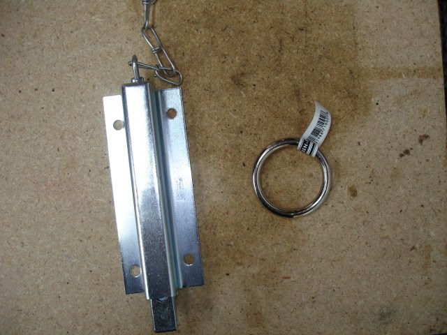
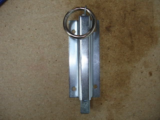
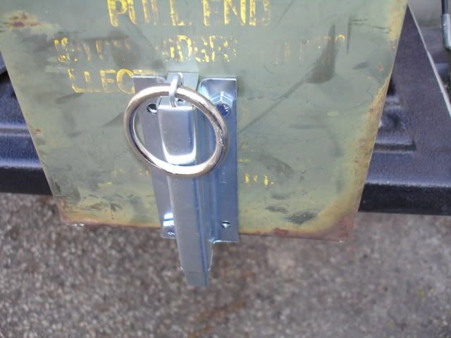
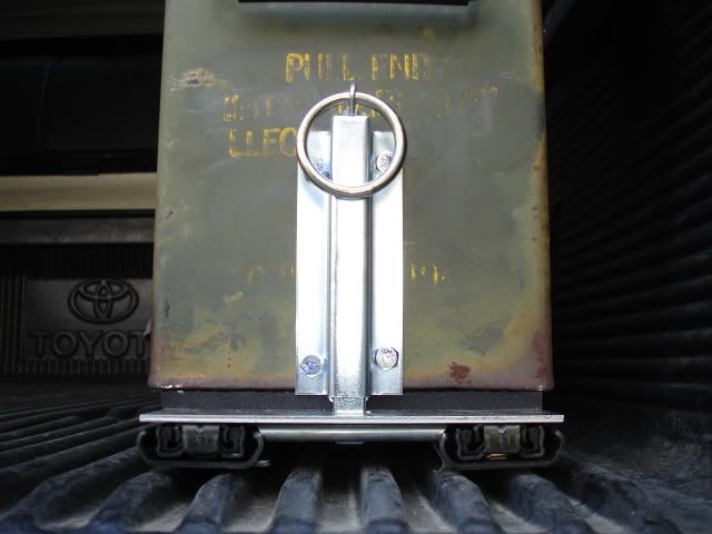
The fence latch assembly came with a chain. I swapped out the chain for a steel ring. Later I added a magnet to keep the ring from banging around. The magnet works really well. I used super glue to secure the magnet. The ring will always return to the "home position".

DSC02702.jpg


DSC02703.jpg


DSC02705.jpg
 

4307

Adventurer
Next, I did a dry fit to make sure I'm on the right track and possibly re-engineer problem spots.
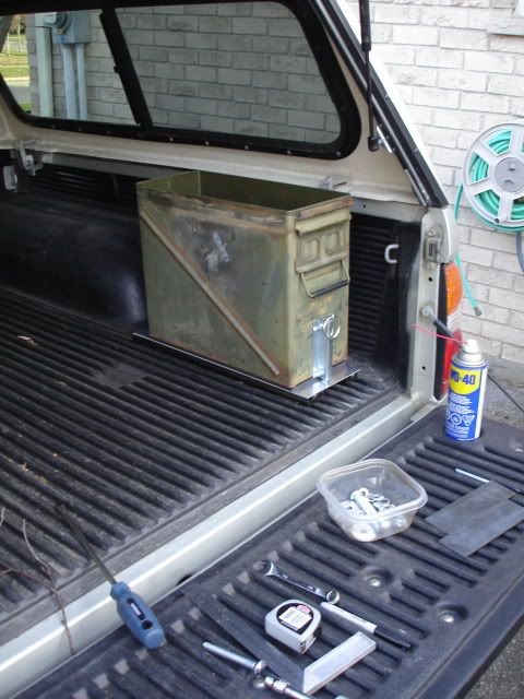
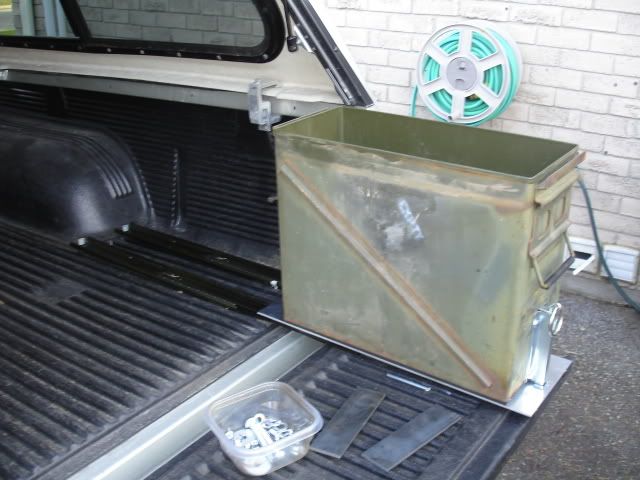
The ammo can in the closed and open position:

DSC02710.jpg


DSC02711.jpg


DSC02712.jpg


DSC02716.jpg
 

4307

Adventurer
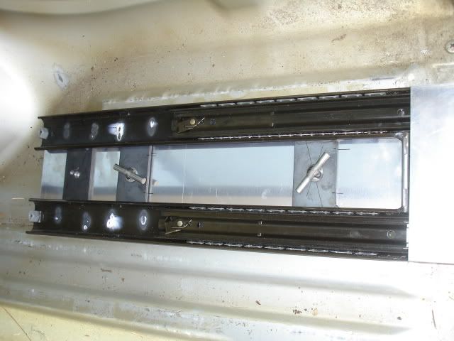
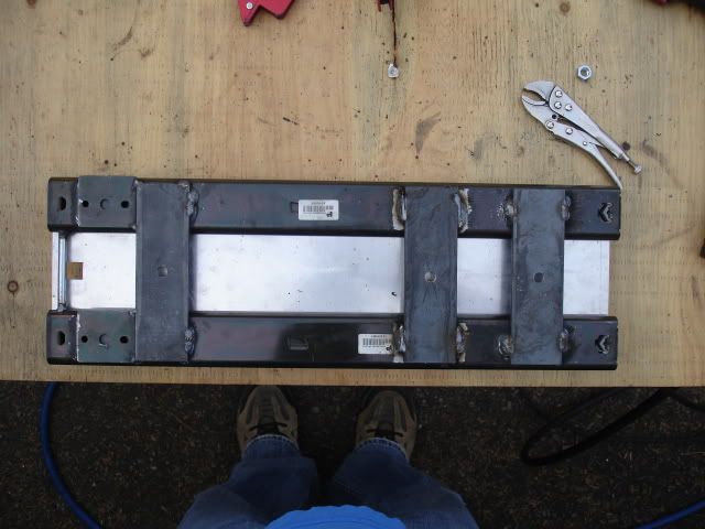
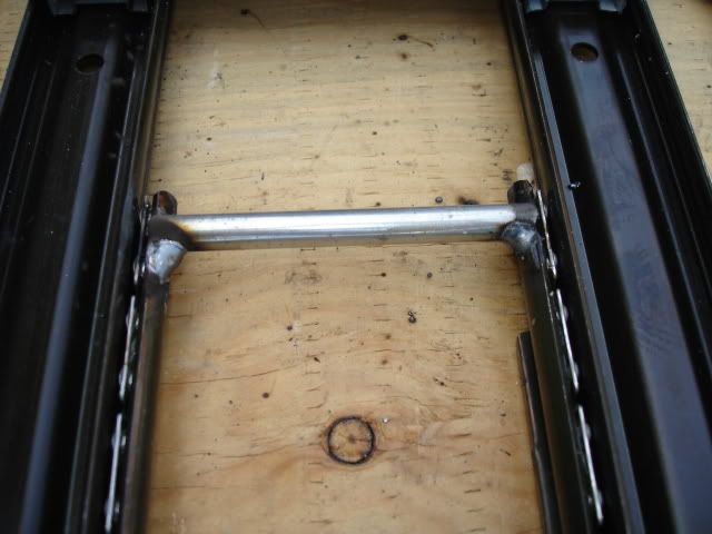
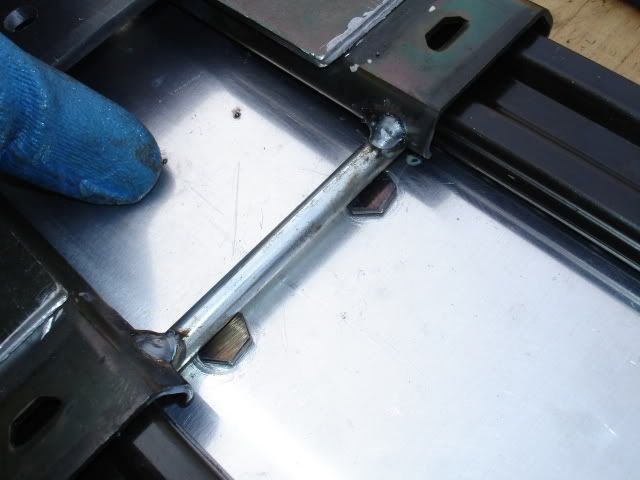
I made some cross members for the slide and welded them into position:

DSC02723.jpg


DSC02762.jpg


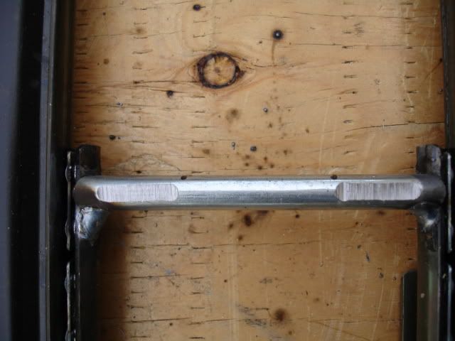
I added the latch lock bar. I had issues with the bolts mounted to the top plate clearing the latch bar, so I did a little grinding:

DSC02755.jpg


DSC02759.jpg


DSC02760.jpg


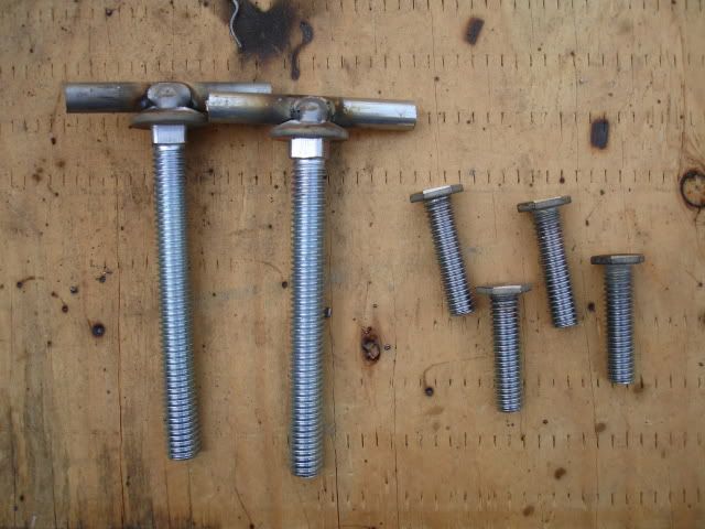
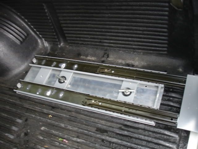
I made some wing bolts for mounting the slide to the bed of the truck. The wing bolts are nice. I don't need tools to take the ammo box and slide out of the bed if I need extra room. The bolts were later cut to correct length.

DSC02757.jpg


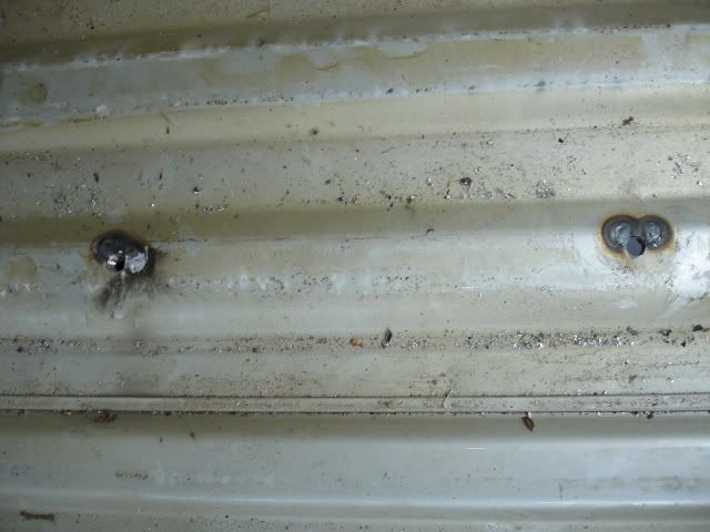
After taking the bed liner out, I drilled holes through the truck bed and welded nuts to the underside. I sprayed some leftover bed liner spray on the nuts and welds to keep them from rusting. The heat marks and damaged paint inside the bed were covered up with some leftover silver automotive spray paint.
Later I put the bed liner back in the bed.

DSC02768.jpg


Before bed liner went in, I made sure the slide fit with the bolts in place:

DSC02770.jpg


DSC02771.jpg
 
Last edited:

4307

Adventurer
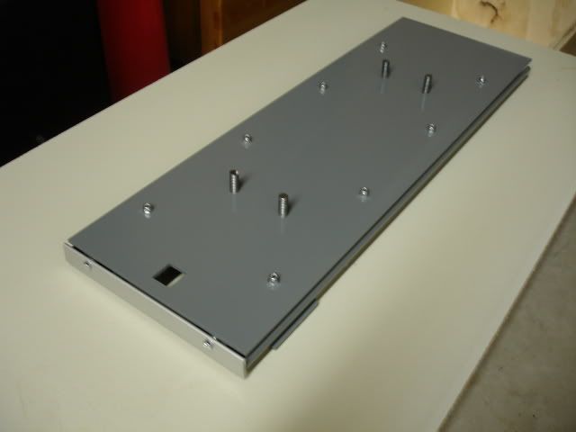
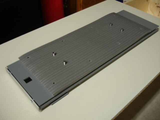
I took apart and painted everything bling Battleship Gray.
I reassembled everything, used Loctite on all the nuts and bolts, replaced some nuts with lock nuts.

The second pic shows the workshop floor mat, (no I didn't paint the foam mat gray). The foam mat is a spacer/ vibration dampener.

DSC02885.jpg


DSC02887.jpg


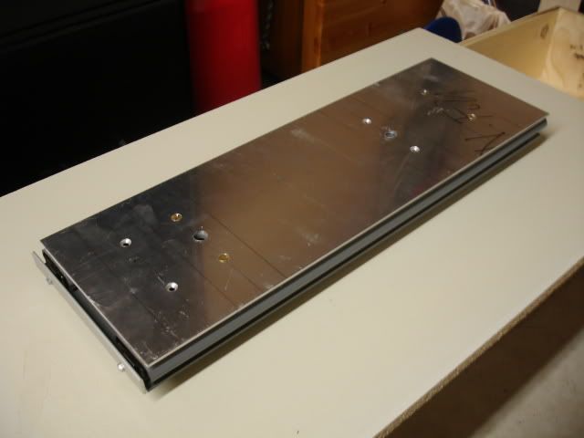
The only thing I didn't paint was the bottom aluminum plate, I may swap it out for a wider plate later.... I have another idea possible add on.

DSC02889.jpg


Here's the finished product.
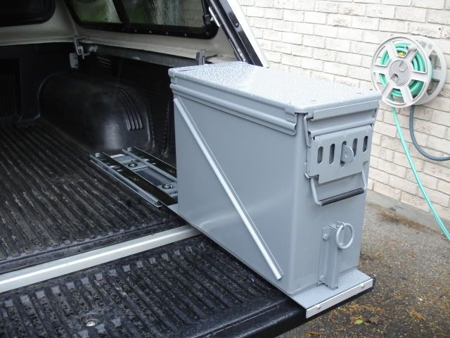
In round of pics the ammo can was loaded with 40 lbs of truck stuff. (yes, I actually weighed the stuff). At 40 lbs @ full extension the slide rests on the tailgate. I designed it to rest on the gate. The slide isn't supporting suspended weight just resting weight supported by the tail gate.
Filing cabinet slides are typically mounted sideways it's designed that way to support fully extended, suspended weight.
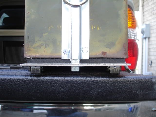
I mounted mine flat. I wanted to keep the slides tucked under the ammo can to save weight and keep it nice and tidy and narrow. At full extension the slide drops slightly but does not effect the slide , its very strong and stable. To slide the ammo can back in you lift it slightly and the slide moves fine with full weight. Works better than I thought it would. The slide only drops at full extension when it passes the edge of the tail gate, I may add a piece of plastic to the molded bed liner on the tailgate edge if it becomes a problem. I think it will be fine the way it is, time will tell.

DSC02892.jpg


DSC02893.jpg


DSC02894.jpg


DSC02901.jpg


DSC02895.jpg


DSC02902.jpg


Here are a couple cheap videos:
The vid is posted by weldergirl I hijacked my wife' s account.

http://www.youtube.com/watch?v=CwWpdXgaJWw

http://www.youtube.com/watch?v=NOoFnceCUDI&feature=related

I hit a local mud hole and corrugated dirt roads and gave the truck a good rattling, shake things up a bit. Every thing is rock solid and the bed bolts never backed off.

UPDATE: It's been half a year since the project was completed, I'm happy to say, the drawer slide is holding up strong. The occasional cleaning of the tracks is nesessary, remove the old grease with a rag and replace with new grease. The ammo can has been carrying the same weight and contents since the build was completed, there are some new dents and scrapes but over all the paint has been holding up better than expected.

I have all the parts to build a second Ammo Can Drawer slide.
 
Last edited:
4307

Adventurer
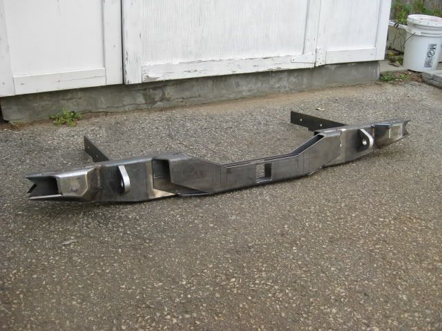
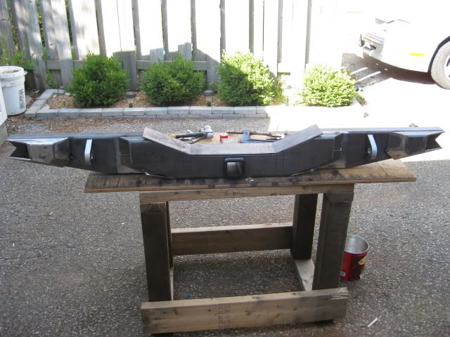
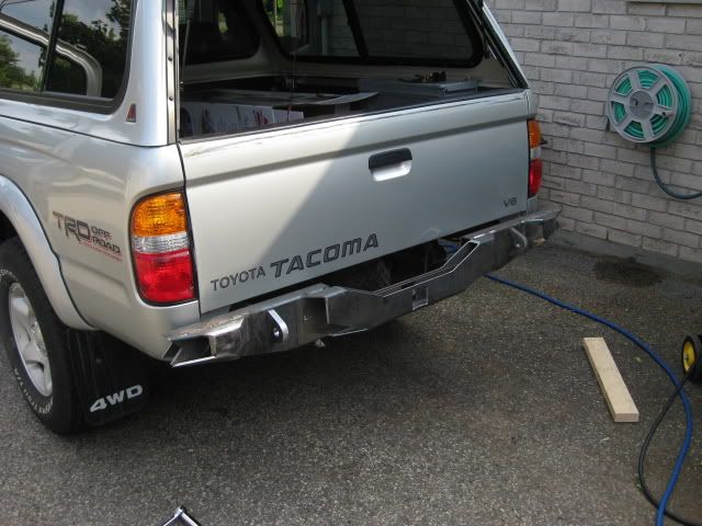
Rear bumper build.....

Well I'm at it I might as well post my current build.... A rear bumper.

I'm posting the process, step by step possibly creating one of the longest single post threads. It might help people with their own bumper builds, then again it might not.

I've been working on and off, building this boat anchor for a while, in my spare time, when the weather is nice enough to weld in my driveway. Lately, I've had time to work on it, thanks to our global economic fun-fest. Gee thanks boss!
Right now I'm trying to finish the main part of the bumper before the snow flies. The weather will beat me too the punch, but what can you do?
I need a garage. In the mean time, I make due.

The main reason for the bumper build is... for the sake of building. It's fun! Maybe not for the neighbors, but hell you only live once. I'm sure they'll get over it.
I'm sure the they cringe every time I whip out that grinder.
Mooo ha ha ha...
I'm handing out ear plugs to the parents for Halloween.
So far my fabricating addiction and my love of noise hasn't been a issue with the neigbours, their pretty cool.

I want some beefy "***" protection! The OEM bumper held up like a champ taking on 4 rear end fender benders, resulting in one minor dent.
The OEM bumper will be my future beer bar in my work shop..... Yippee!
I want something that will scare people into not hitting me... if they do, they're in for some big damage. Other important requirements... tow and recovery points.

I went out of my way to take enough photos to give this thread some "meat", documenting the main steps of the build.
I thought about copying other designs but opted for originality, something different to test my skills.
The design is different but beefy, possibly deflect bullets and give the illusion of stealth technology to thwart radar guns..... I have a vivid imagination. LOL.

The bumper is made primarily of 3/16'' , 1/4'', 3/8" stock - plate and rectangular steel tube.
3/4'' stock was used for the Clevis recovery points, I could have bought them, but thought... " What the hell, I'll fabricate them myself.
I incorporated a trailer hitch box receiver just in case I decide to tow something like a M101 military trailer, if I ever decide to get one...
Possible future build.

I plan on cutting the rear quarter panel for high clearance. The bumper will accommodate side panel, detachable, high clearance square tube protection, yet to be designed and built. The side protection attaching points have been incorporated into the corners of the bumper..... you'll see.
I'm also adding brackets for rock lights on the inside of the bumper.
Air lines: female couplers will de added. on either side and rear of the bumper, for tire inflation and the air mattress for our tent. I thought about turning the bumper into a air tank for use on the trail, but a tankless, good air compressor will do just fine, I'm not in a race.
The bumper and side protection will be strong enough to use a Hi-Lift jack.

A swing out tire gate will be designed, steel cut and dry fit this winter in my basement shop, ready for welding in the spring. Unless I come up with another solution for the spare tire.
The bumper will not be installed until spring, I'm not planning on wheeling this winter anyway.

This spring my truck will see real transformation when the pile of parts are finally glued to the truck. I'm in no rush, there are still a few parts I need anyway.

The main tools I used were:

- A frickin loud disk grinder
- die grinder
- Miller 175
- my trusty band saw (I love that thing!)
- various magnets
- my hands and brain
- ruler, level
- air wrench
- jack stands
- camera
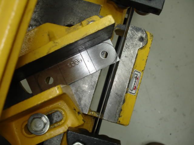
- flat stock bender
- blowtorch
- drill press
- jig saw
- Beer
- belt / table grinder.... and a few other tools, I can't think of right now.

Well enough jibber Jabber, heres the build.....

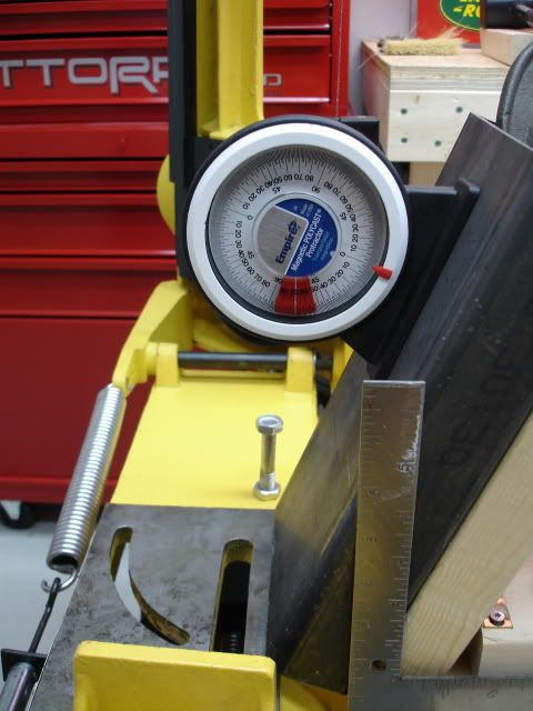
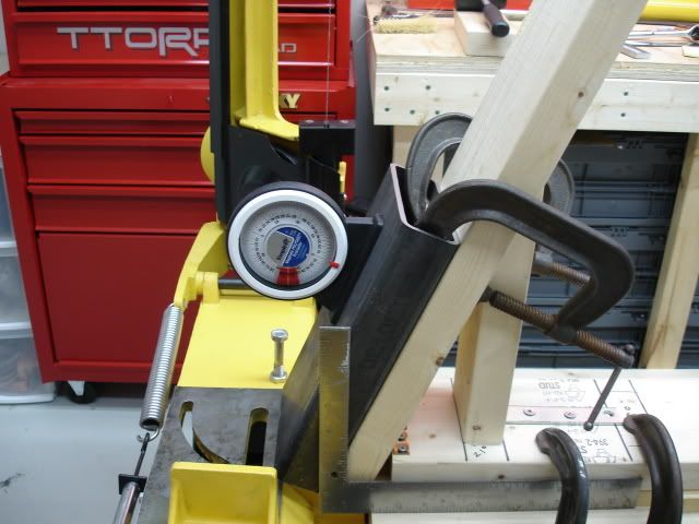
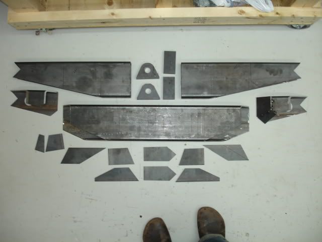
First thing I did after making some sketches and taking measurements and buying stock, is cut the rectangle tube stock into the lengths and angles needed.....
I'm not including the pics of my drawings, they were destroyed by a beer explosion. I'll build up the drama by posting sequence pics. LOL...

DSC01084.jpg


DSC01086.jpg


DSC01099.jpg


DSC01100.jpg


DSC01101.jpg


DSC01102.jpg


DSC01103.jpg


DSC01106.jpg


DSC01107.jpg


DSC01109.jpg
 

4307

Adventurer
Next I cut the box tube for the driver and passenger side higher clearance profile....

DSC01268.jpg


Clevis recovery points.... The next thing on the agenda.
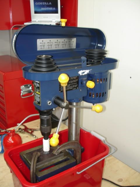
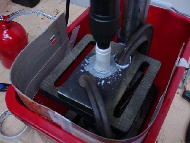
I used 3/4'' steel blocks. This build was a complete experiment, largely due to the fact, I was using a Master Craft hobby bench-top drill press and 1'' Bi-Metal hole saw. LOL....
Lets just say I put this machine to the test and then some.

I'm very impressed with this drill press. I will be upgrading it eventually, hopefully with a mill drill or milling machine.

The key to drilling thick steel with this drill press is:
- dropping the dill speed as low as possible
- clamp the work so nothing shifts
- drill a small diameter guide hole
- use a lot of cutting lubricant.
I took my time, keeping the heat down, stopping to cool the motor, in the mean time I used a Shop Vac to remove metal shavings.
I didn't force the pressure on the drill press to speed up the cut!
After drilling two hole with the hole saw, the saw was still sharp.
You'll notice I put the drill press in a bucket, with some card board taped too the inside of the bucket. This was my solution to keep the sloppy mess down, making it easier to clean up.

DSC01412.jpg


DSC01416.jpg


DSC01418.jpg


The hole saw cut turned out better than I though.
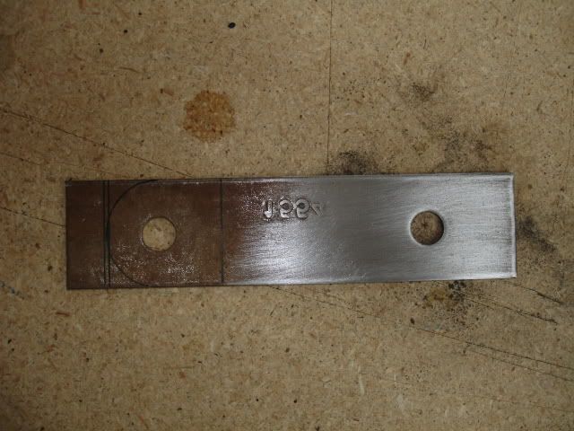
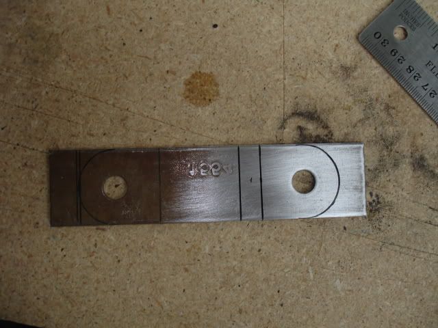
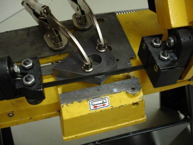
the next step was too cut the 3/4'' stock into the shape of a clevis point....
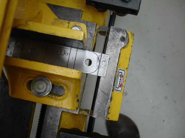
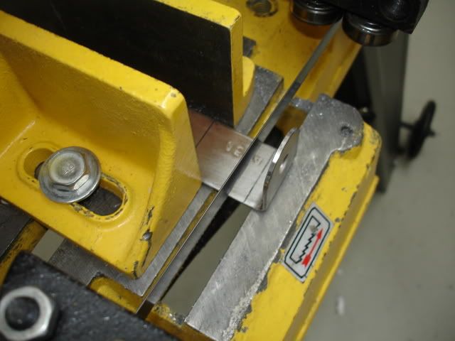
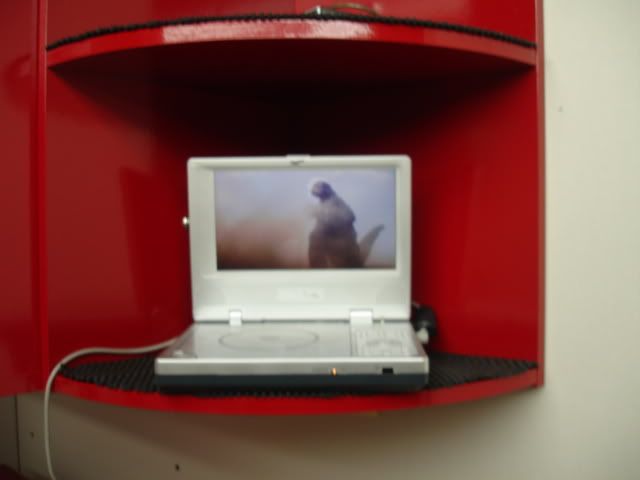
Back too the band saw... The cuts take a while. While I sat there baby sitting the saw, Godzilla was entertaining me... Godzilla vs. Mothra. Classic!
I love monster movies.

DSC01420.jpg


DSC01421.jpg


DSC01423.jpg
 
Last edited:
4307

Adventurer
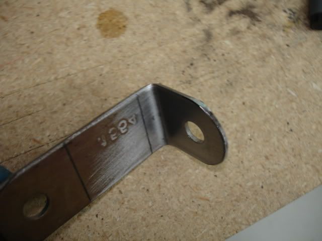
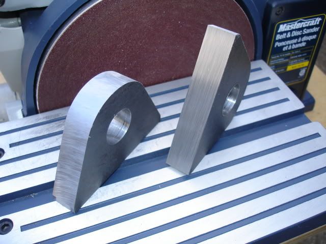
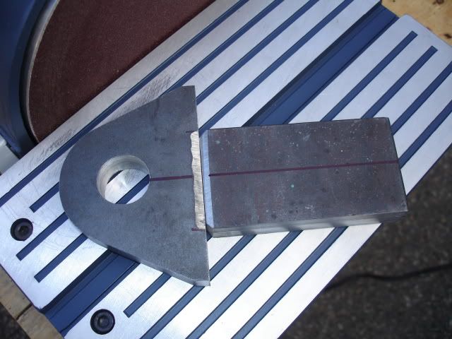
The next step was giving the cut edges of the clevis a smooth finish, for this I used a table disk/ belt grinder.
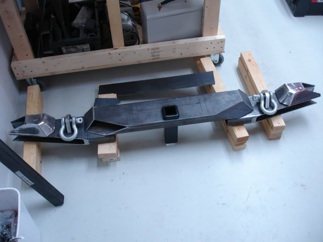
The clevis I designed is meant to go through the bumper, welded on either side, front and back of the bumper, as well as the inside of the boxed section of the bumper. Over kill!
The clevis will be connected to the mounting brackets that attach directly to the frame.
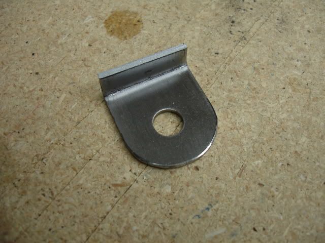
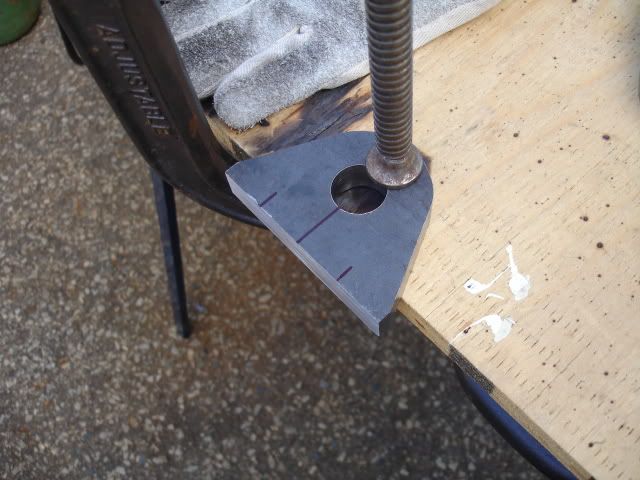
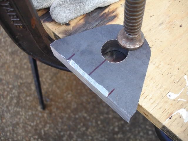
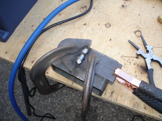
I used two pieces for the clevis points welding them together too make one piece. I beveled the edges of the clevis parts were the weld would be applied. I managed to get pretty good penetration. I put one of the clevis points in a vise and gave it a couple good wacks with a hammer to see if it would crack the weld. All was good so I ground the excess weld down to clean up the surface.

DSC01438.jpg

DSC01426.jpg

DSC01439.jpg

DSC01440.jpg

DSC01441.jpg

DSC01442.jpg

DSC01443.jpg
 

4307

Adventurer
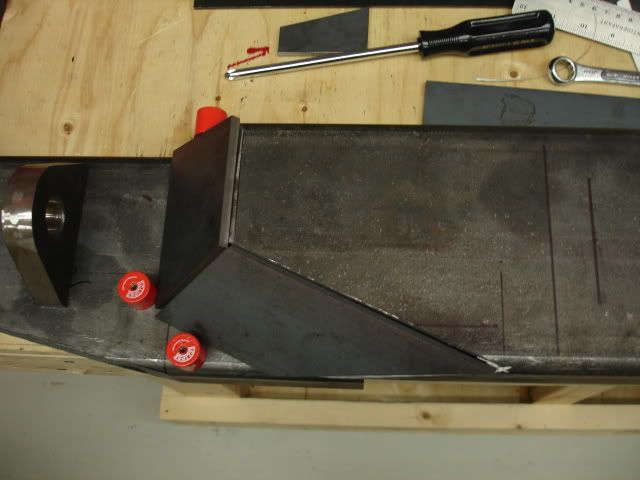
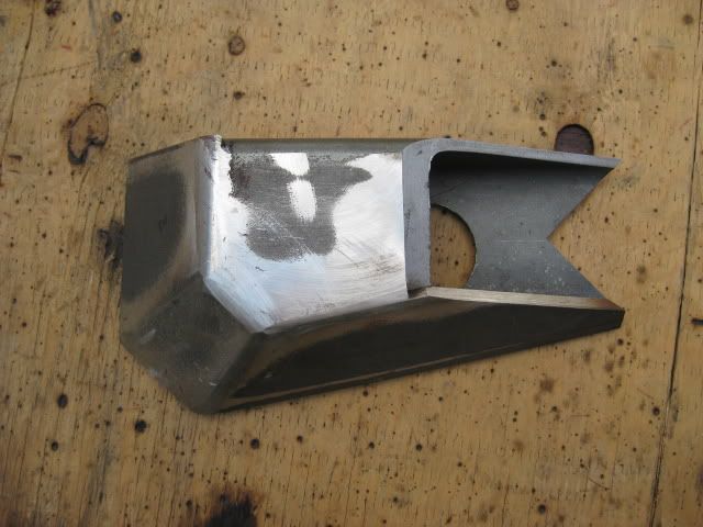
The bumper corners are unique. The main purpose for this is: Too give the bumper some extra beef and depth, more area to" weld in" hinge towers with gussets for the swing out gate, recess the clevis points so they don't stick out too far on the out side surface of the bumper, and.....
To be different.
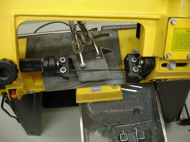
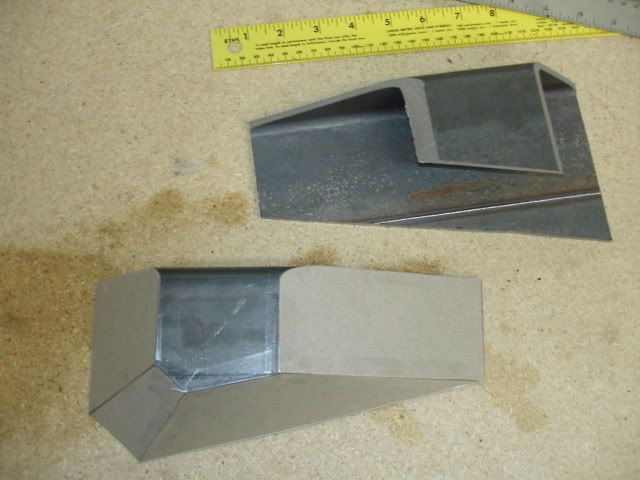
I used the band saw to create the main pieces for the corners.... confused yet?

DSC01286.jpg


DSC01288.jpg


I used card board for the plate templates to get the general shape....

DSC01289-1.jpg


I used 3/16'' plate steel for the angled surfaces....

DSC01290-1.jpg


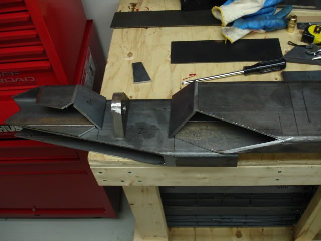
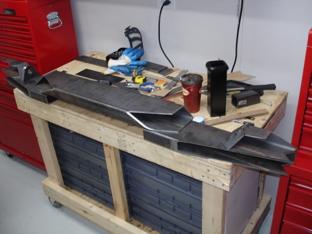
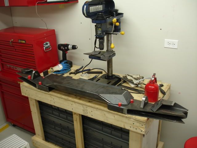
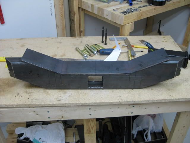
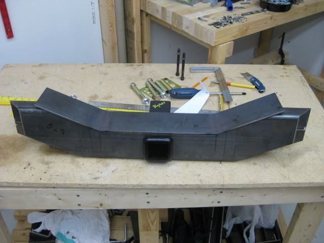
Ok here is the basic layout of the bumper on the work bench....

DSC01390-1.jpg


DSC01391.jpg


DSC01392.jpg


DSC01395.jpg


DSC01399.jpg


DSC01427.jpg
 

4307

Adventurer
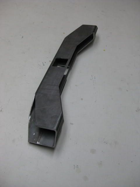
A box trailer hitch receiver is part of the bumper design. I wanted to keep the receiver as high clearance as possible. In order to achieve this I had to cut a 2-5/8'' x 2-5/8'' square hole out of the bumpers mid section to fit the receiver through the bumper.
This step was another challenge. It would be a piece of cake if I had a plasma cutter. I could have called a family member that has a plasma cutter but I like doing things the hard way.
I was up for another challenge and devised a plan.....
Taken from a old-school tool and die technique, I perforate the rectangle box with a drill press. After perforating both sides of the box section, I used a jig saw to cut through the perforations. Worked like a charm! I didn't bother grinding the inside edges flat. I ground just enough to fit the box receiver through the bumper, nice and square.
See! I don't need a stinking plasma cutter!
Ya right!.... I just can't afford one right now.
Unfortunately this is the only pic of this step, you'll be able to see it in later pics.... I think.

DSC01838.jpg


Back to the bumper corners.... I welded the angled plates into position and ground the welds, smoothing them out. I also used a hole saw to drill out holes on the backside to lighten up the corners.....
What a time too nickel and dime. If I had a plasma cutter I would have removed more steel.
For the most part the fancy corner thing-a-mabobs do not weigh all that much.

( I'm doing a 63'' rear Chevy leaf spring swap so the weight factor is a not all that bad, although that may change if I decide to mount a spare tire gate, I may have to add a forth leaf, but thats another build.).

The outside corner edge looks pretty scary!
I notched out the corner to accommodate square tube for the side quarter panel protection ( trimming the fender for higher clearance) originally I was going to mount the tube square to the ground, but just to complicate things I decided to clock the tube 45*
The next photo shows what I had in mind regarding the 45*.... Fancy, eh?

DSC01372.jpg


IMG_0522.jpg


IMG_0523.jpg


During the build I would assemble the parts, take a picture or two and think about what I have, making sure it will still work.
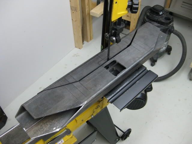
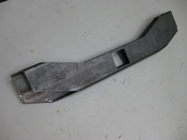
After looking at theses pics, I decided I could lighten up the bumper, a bit, by taking out a section of the center piece above the receiver hitch. this would possibly help lower the height of a spare tire, I won't know until I get to that stage. Another use for the change would be a step. It could be handy for adjusting loads and straps on my roof rack. The step would also transform the bulky look of the mid section.
I'm also using the step plate as part of the gusset for the hitch receiver and re-box the mid section.

DSC02096.jpg


IMG_1079.jpg


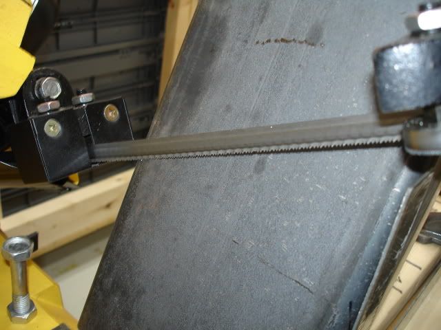
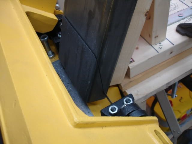
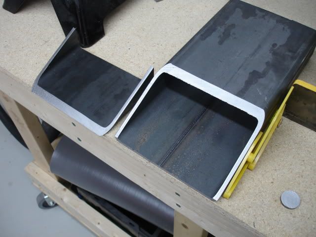
I used my trusty band saw to remove the material to create the step. It was a slow process.
It's amazing what you can do with a band saw. I used the drill press again too drill the corners so I can pivot the band saw blade too cut straight across the box mid section.

IMG_0206.jpg


Here's the mid section from different angles....

IMG_0207.jpg


IMG_0209.jpg


IMG_0210.jpg
 
Last edited:
4307

Adventurer
The after pic of the mockup assembly.....

IMG_0215.jpg


After the mid section step was cut and evaluated over a cold beer. The next step was creating a step plate.

I thought about using diamond plate but after visiting the steel store, my measurements and cardboard template indicated diamond plate would not be the best solution.
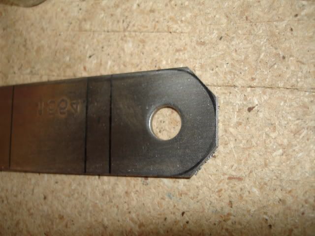
I wanted to use a one piece plate with bends rather than three plates welded together to create the angle.
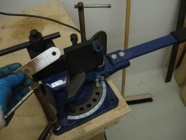
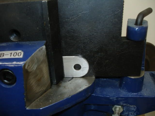
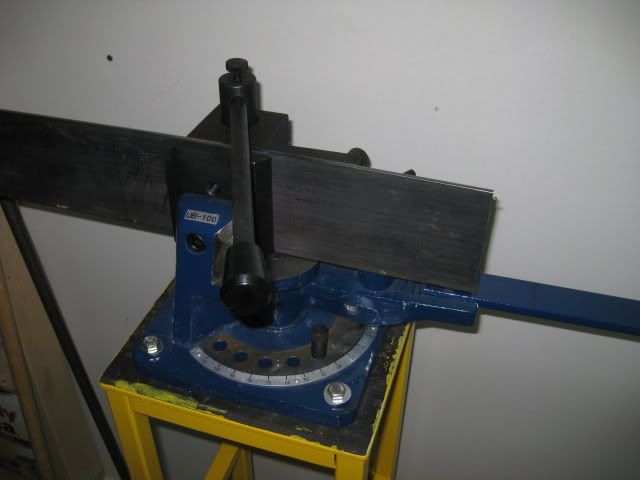
I have a plate and angle iron pedestal bender. (another tool, I love!)
The diamond plate would be hard to bend, the diamond pattern also didn't work well with the measurement I had.
I decided to go with 3/16'' standard flat plate steel.
I can add a anti slip surface later in the build..... Like grip tape, spray on / roll on bead liner, or weld my forum name / signature on the surface of the plate.... the creative juices are flowing again. LOL.
Anyway....

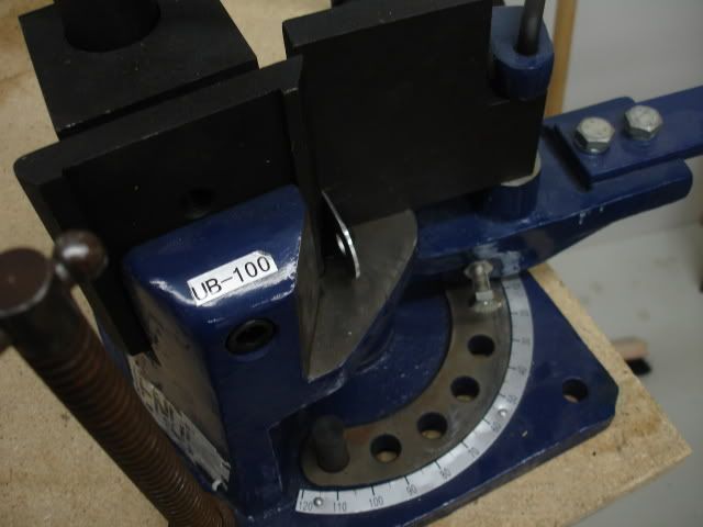
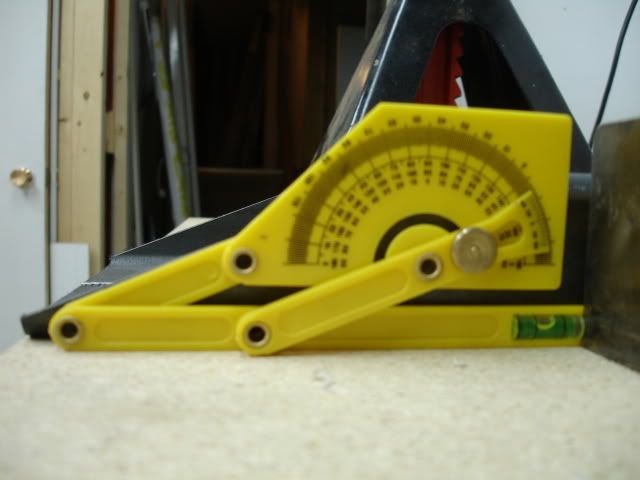
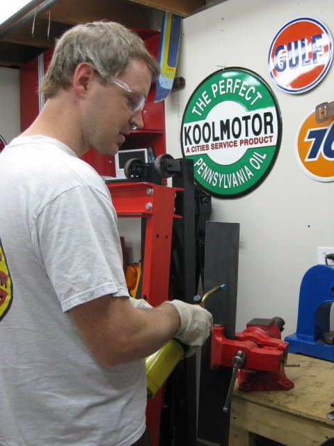
Before I do any bending, I double checked the measurements with the template, cut the plate to a slightly longer length (just in case), mark the plate where the bend will be, Place the plate in a vice and add heat. I used a MSP* gas (methylacetylene propadiene, stabilized.), also known as MAPP gas. I used this gas over propane because it will burn hotter. The hotter the bend location is, the easier it is to bend the steel, creating a sharper bend Some times a radius bend will occurs with cool steel, heat is required with this type of bender.

Here's an ugly of me, the bender and the result....

IMG_0513.jpg

IMG_0517.jpg

IMG_0519.jpg

IMG_0521.jpg


Tack weld time!
Well, before I get ahead of myself, the Clevis points mount through the bumper, I figure the recovery points will be stronger that way, rather than welding the clevis points to the surface of the boxed section with no material between the recovery point and the frame brackets.

I used the same technique to remove material, as I did for the hitch box receiver... perforation holes with a drill press and cut with a jigsaw.

IMG_0525.jpg

IMG_0526.jpg


Back to the tack welds. I had the measurements of the outside frame width. Having measurements, I tacked up the bumper so the out side edge of the clevis points match the width if the outside mounting surface of the truck frame.
With the tack welds in place, it gave me a rough idea of how much I would have to tweak the distance between the clevis point to make the new mounting brackets fit the frame. I ended up grinding off the tack welds three times to get the proper distance between mounting brackets.

IMG_0536.jpg


Bumper mounting brackets: I used 3/8'' steel stock.

Before cutting and drilling, I used cardboard as a template to locate the OEM mounting holes on the truck frame and weld locations of the OEM shackle hanger welds.
After cutting and drilling the mounting brackets, I did a dry fit to make sure the bracket holes match the frame holes, I bolted the brackets to the frame and took bracket length measurements so I can cut them to the proper length. Then removed them.

I took the time to fabricate bracket tabs to help support the bumper weight on the inside of the frame, while mounting the bumper, just like the OEM tabs.
The tabs make it easier for one person ( me ) to position the bumper on the frame. I then position jack stands under the main part of the bumper to carry the bulk of the weight while I bolt the bumper to the frame. Its a real back saver.

Next, I tack welded the brackets to the clevis points, them mounted the bumper on the truck. Like I indicated earlier, it took three attempts to get the distance between the brackets right to match the frame width. I managed to get a perfect fit. While I was at it, I welded the top of the corner thing-a-mabobs so I can grind the welds flat to make the bumper top surface look like one piece. Grinding came later.

IMG_0695.jpg

IMG_0697.jpg
 
Last edited:
4307

Adventurer
Its tricky welding outside, the wind tends to blow the shielding gas away, I managed to get some half decent welds. There was a lot of weld applied to fill the gap between the pieces, I then added smaller filler welds to even it out.

IMG_0698-1.jpg


Again I took pictures of the bumper, earlier, of the boxed hitch receiver and step plate, in their rough position to get an idea of how they will fit. That way I can sit back in the evenings and think, without wasting the day away dreaming about the solution, with the bumper in front of me. If I had a garage that might be a different story, and I don't feel like lugging that thing down stairs. ;)

IMG_0529.jpg

IMG_0532.jpg

IMG_0534.jpg


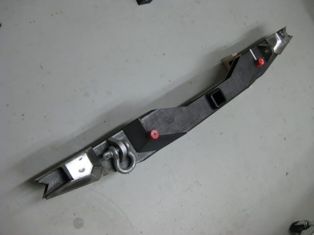
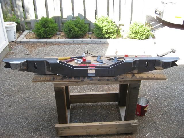
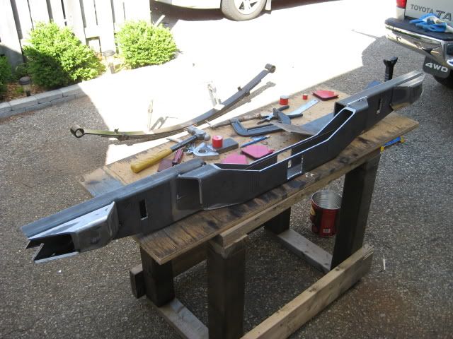
This is the bumper mounted at the tack weld stage. The result was a perfect fit.
Scary corners eh? LOL. It made a few friends scratch their heads. Its a fricken weapon!

IMG_0683.jpg

IMG_0686.jpg
 

Forum statistics

Threads
188,361
Messages
2,905,996
Members
230,117
Latest member
greatwhite24
Top