You were meant to take away from my experiential examples, two things, 1) That NEITHER genuine Anderson nor their copies will support the load they claim. I do not believe that the copy I used was significantly lower in ACTUAL capacity than the genuine. By allowing excessive alternator output, I precipitated its destruction. 2) That alternator's rated capacity is just one number on the whole performance curve of an alternator. Given a low enough battery internal resistance, you can drive it to higher than its rated capacity. This excessive capacity can be survivable if the excessive temperature is prevented (which I did and do).
I am a mechanical engineer with lots of professional experience with DC power, aerospace and high current commercial connector design and manufacturing. I have had several negative experiences with genuine Anderson connectors and decided to see how the Anderson copies compare. Other than the nickel plating instead of silver, they were very well made. Contacts were well-formed, thick and solid copper. The housing was also thick and well molded. Being 'copies' it also retains the inherent design flaws of the genuine.
Connector selection is about 'appropriate use' and not about getting the highest performance when it is not needed. By the same token, connectors need to meet their specifications. I believe that my copy was very comparable to the genuine Anderson. I was anticipating current in the 100-120A range because, at the time, I knew that the 120A rated alternator would likely only produce 60A continuous duty but I expected it to peak at its max rated 120A till it overheated and the thermostat began to cycle it on and off (based on temperature bot approximately 10' on/5' off cycle). A 175A continuous duty rated connector seemed appropriate (and still does if either actually performed to spec). I made a mistake in my initial telling of the story. The first failure was crimped and the second was soldered. The first failed when I was in a campground, 2000 miles from my crimper so had to repair it with solder. I am fully aware of the undesirability of solder. I attribute the first (crimped) failure to cable twisting the contact, which is an Anderson design issue (part of my prior Anderson failure analysis), and the high amperage, precipitated failure.
Its worth noting that my prior failures with the genuine Anderson arose from a fundamental design problem which it still has. The contact surfaces are flat and must remain in perfect contact in order to support the load, but they rarely do. The housing does not prevent the contact from turning other than by the 'spring finger' used to retain the contact. If the cable is twisted in operation, or if it is not VERY FINELY STRANDED, the contacts turn relative to each other and even a tiny amount, resulting in their high contact temperatures (yes, Anderson admitted this to me).
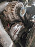
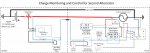
At the time of this incident, My dedicated 120A/29.4V alternator (then a pre-set voltage output) had a thermostat in line with the excitation of the external regulator that limited the alternator case temperature to 120C. This system works well and has been tested extensively both before and after. While not explicitly controlling current (in this iteration of control), I enforce a duty cycle on the alternator by directly monitoring temperature. I also had voltage, current and temperature monitoring of the alternator in the cab so I was fully aware that it was producing 150A (undesirable but by itself is not a problem) into a cable/connector system that should have been able to handle it. What I did not have (and have now) is the ability to easily dial back the voltage output to reduce the amperage output.
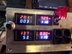
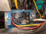
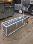
In the latest control setup, I have 'operated' on my Transpo Voyager adjustable external regulator and replaced the embedded 10k adjustment potentiometer with a panel-mounted 10k precision potentiometer. (see attached photo). When I want to charge, I turn on the master switch (upper left) which supplies excitation, I check the voltage and current output (top row left) of the alternator (now a 220A), based on the current battery (last picture) SOC and use the trim pot (upper left) to adjust the alternator voltage set point to achieve a corresponding (max) current I want. At this point, I can hit the road and pay no attention. With a fixed voltage output, as the battery charges, the current will decline naturally. I periodically increase it if I want. If I'm producing more current than the alternator can sustain continuously, the thermostat will cut charging at 120C and restart at 110C.
I have several video clips on my Instagram feed @maximum.4x4.camper that show it in operation. There are more detailed writeups on my blog, workingonexploring.com and some videos on YT (search 'workingonexploring').