Any good solutions for two radios on one external speaker?

troyboy162

Adventurer
good stuff. The premade one sounds nice, but I think I can do this cheaper and more ideal for my set up. This is a update to where I am at. I think the circuit is good enough to build now and I will have time to try in next month. You can see the parts add up pretty fast, but premade things are $70-$200 and not really set up for what I want to do, well hope to do :)

so far it does these things
-cuts music when ever cb or ham are RXing
-mixes three music/navagation/whatever else is not as important into one signal
-delays putting the music back on for ~4 to ~30 seconds (adjustable)
-by grounding a point you can shut off all music with one button and give the speakers to the cb/ham if you need to do extended talking.
-cb and ham input speaker output should have the ability to be adjusted down to headphone level like a cell phone or ipod.

truck.JPG

parts list:
3 POT 10K 3306F-103-ND $.60 each

1 POT 100K 3306F-104-ND $.60 each

1 2N2222A BJT NPN P2N2222AGOS-ND $0.39 each

1 LM358N op amp LM358NFS-ND $0.46 each

2 1N914 diode 1N914BCT-ND $0.10 each

6 RES 1K OHM 1/8W CF18JT1K00CT-ND $.065 each

6 JACK AUDIO 3.5MM CP5-43502PM-ND $2.73 each

1 .1uF cap DC blocker 478-1831-ND $.63 each

1 47uF cap 399-3592-ND $3.46 each

4 10k 1/8w CF18JT10K0CT-ND $.09 each

1 100k 1/8w CF18JT100KCT-ND $.09 each

1 DPDT relay TQ2-12V-3-ND $3.45 each

1 proto board V2025-ND $6.20 each

1 metal box

1 SPST switch for music cut off by grounding relay coils
 
Last edited:

DaveInDenver

Middle Income Semi-Redneck
What are you assuming the output looks like from XLV2/7? Those are to be ham & CB speaker outputs? I ask because it looks like a DC analysis to me.

You should control the gain of the second stage op-amp, right now you're asking it for infinite gain with no feedback. That'll work in SPICE but not the real world.

It looks like you haven't given the first stage op-amp it's rails? Also, correct me if I'm wrong, but won't the circuit latch when you close S9?

I would impedance match to the amp and rectify in the first stage, amplify in the second and then build your relay driver with the open collector. I wouldn't put the manual override switch in like that, but it might be made to work.

That circuit is unique, I'll give you that!
 
Last edited:

troyboy162

Adventurer
the vox is a circuit I found on the internet. Its just two op amps in one IC. The first stage amps the input and adds a DC bias ( aka rectify). The 100k here is debatable but makes a square wave thats good for the next stage. The second stage is a low performance comparator. Since the comparitors rails are +Car battery and ground, It will output its +rail (12-13.8V) whenever there is a signal higher then the reference voltage. The second stages output is pulsed and continually saturates the transistor (with the help of the cap) so it can be used as a switch for the relay coils. the HAM/CB and the music are just two separate resistive mixers that the relay picks between.

The signals from everything I have figured are just AC signals of 1ish volts for stereo cell phones/tablets and maybe ~2 volts for the mono ham/CB speaker outputs. I put both at 200hz to guesstimate a human voice frequency. The 10k pots will be used to knock the speaker level outputs down to the same as the phone/tablet by ear with the volume.

the grounding switch on the relay coil is just a way to kill the music. It would seem to work well in theory. killing the music automatically via the vox works great if I am responding to people, but if I want to start a conversation or do some extending talking with the HAM/CB, then hopefully a small toggle switch will replace the need to fumble for volume sliders on one or two touch screen devises. Just turning down the stereo wont work anymore since that would turn down everything.

I think I've covered my bases. It simulates well, is based of proven stuff, and I'm pretty sure it wont burst into flame. Its at least bread boardable right now for a test run.
 

DaveInDenver

Middle Income Semi-Redneck
A couple of ideas that I think would work better. Use a FET switch instead of the 2N2222. Nothing wrong with BJT switches but it'll be easier to guarantee saturation when you drive voltage instead of current. Especially trying to drive the base with an op-amp you have to be mindful you'e able to source enough current to keep the switch turned on completely. The LM358 is probably good to about 20mA would be my guess but it won't like being held there for long periods without a heat sink.

Also while you're designing your circuits remember most op-amps don't drive to the rails, they'll drive to about ~1.5V below the rail. So assume worst case 10.5V and not 12V. Forgetting this is often the reason device operation gets funky when a car is not running. Your supply with the engine running is 13.5V and so the rails are running at 12V, but turn off the car and the rails drop.

Anyway, you can switch the amount of current flowing through the coils much safer with a FET than a 2N2222. You're going to have a few amps steady state, which is too much for a little guy like a 2N2222. Even in a TO-18 can we derate the 2N2222 to about 250mW and we usually don't let them be a single point switch for more than 100mW, they almost always get paired in that case. But this is for high reliability and where my designs go it ain't easy to fix 'em... That is the main concern I have, you're asking a 2N2222 to switch 6A in that circuit, assuming your coil characteristics are correct. The data sheet absolute max on them is something like 1A and that's going to be instantaneous not steady state.

FETs have milliohms of Rds, so there is very little voltage drop across them even at several amps and they don't heat up much. They are easier to design into saturation (Vgs only needs be a few volts) and there's less chance of them going into the linear region with temperature. Personally in a low side switch like this switching relay coils no doubt I'd be using an N-channel. A 3707 or something is probably $1.

Speaker output is typically about 2V and you'll have to dissipate a few watts maybe, so be sure to size your impedance matching is sized appropriately. I would at least model the speaker outputs with a generic common emitter amp with an 8 ohm output impedance to see. It's AC with (ideally) no DC offset, so you need to rectify and filter it into DC. The range of frequencies will be around 2KHz, you'll get very little spectrum below 200Hz and above 4KHz, the majority of your energy will be 1KHz to 3KHz. I'd also consider an isolation transformer, you'll probably get some buzzing otherwise plus you don't want one radio being a return path for the other or another circuit in your truck.

Using an op-amp open loop as a comparator is fine, although no one has done that for a long time (actual comparators exist now that work better). When you do you have to be careful to protect the output of the op-amp prevent oscillation or failure. That's why I cautioned you because things like that work in simulation but cause stability problems when you realize the circuits in the real world.

How about designing a latch specifically and use a timed reset after the 2-way signal drops?
 
Last edited:

DaveInDenver

Middle Income Semi-Redneck
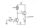
Maybe use something simple to model the external speaker driver on the radios. I don't imagine they would be anything fancy, probably some sort of IC, but this should suffice for SPICE.

quick_audioamp.jpg

ETA: I think I dropped that current source in wrong, whichever editor you are using, you want SPICE to see the current flowing into the base of Q1.
 
Last edited:

DaveInDenver

Middle Income Semi-Redneck
BTW, I think the brute force shorting to energize the relays is fine, just inelegant. :) In this case I suspect it's the only way it's going to work because normally I don't see you switching enough current without driving 50mA into the base of the 2N2222 and even then regardless of the data sheet gain value it just won't do that Ic.
 

troyboy162

Adventurer
The change to FET sounds good. I am slowly absorbing the rest of what you wrote. Its taken me alot of time to figure out as much as I have lol. If and when It works I will be sure to post it all up so others wont have to stumble like I have been haha. The relay values arent real. They are just what ever multisim had. I assume a through hole relay will have a very low current for a small package (looks about the size of a piece of bubble gum, but I will double check the datasheets to make sure they have a have some internal resistance.
 
Last edited:

DaveInDenver

Middle Income Semi-Redneck
The change to FET sounds good. I am slowly absorbing the rest of what you wrote. Its taken me alot of time to figure out as much as I have lol. If and when It works I will be sure to post it all up so others wont have to stumble like I have been haha. The relay values arent real. They are just what ever multisim had. I assume a through hole relay will have a very low current for a small package (looks about the size of a piece of bubble gum, but I will double check the datasheets to make sure they have a have some internal resistance.
Yeah, using big relays like you show didn't make sense. What you are looking for is (I think) PCB mount signal relays. The little ones are usually good for an amp or two on the contacts, usually up to about 50VDC and probably 125VAC. They'd work fine for the two-way radios, although you might have to be careful if your stereo is high power. Larger ones should be alright for 25W, maybe 50W. Those would be the 5A or so max. Anyway, the coil resistance on these are going to be much higher, more like 250 to 500 Ω and probably no reason to bother with modeling their inductance. You'll be looking at Omron, Panasonic, Axicom, NEC, Fujitsu.

Multisim, eh? You must be a student. Engineering? Last time I used that software was school, it came with the Sedra & Smith microelectronics book. Anymore most people use LTSPICE for simulations and I've used either Altium or Mentor schematic capture and layout tools for regular designs and PCB123 for quick turns. At home I use Eagle PCB, too, sometimes.
 

troyboy162

Adventurer
Take a small stereo amp.. Radio 1 to left channel Radio 2 to right channel. Connect both channel outputs to a single speaker.
There is a little 9v radio shack amp that some have used to do that. It works well for alot of people, but i didnt want to worry about batteries. A few guys report running it on car voltage is fine though.
Yeah, using big relays like you show didn't make sense. What you are looking for is (I think) PCB mount signal relays. The little ones are usually good for an amp or two on the contacts, usually up to about 50VDC and probably 125VAC. They'd work fine for the two-way radios, although you might have to be careful if your stereo is high power. Larger ones should be alright for 25W, maybe 50W. Those would be the 5A or so max. Anyway, the coil resistance on these are going to be much higher, more like 250 to 500 Ω and probably no reason to bother with modeling their inductance. You'll be looking at Omron, Panasonic, Axicom, NEC, Fujitsu.

Multisim, eh? You must be a student. Engineering? Last time I used that software was school, it came with the Sedra & Smith microelectronics book. Anymore most people use LTSPICE for simulations and I've used either Altium or Mentor schematic capture and layout tools for regular designs and PCB123 for quick turns. At home I use Eagle PCB, too, sometimes.
Yes i think the relay i want to use has those exact input specs and the coil is rated for 12v. I expect a couple more volts on the coil will be ok.
The fet simulates a little different in regards to the delay circuit but the specs and easing the load on the comparator sounds like win/win. Thanks for the advise.
10 years ago i got a associates in electronics and thats where i learned about multisim. I wasnt that great with it then and the old saying of use it or loose it could not be more appropriate lol. I tried ltspice but i dont have the time to learn its ways right now. Its been fun jogging old memories loose to figure things out again.
 

DaveInDenver

Middle Income Semi-Redneck
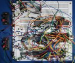
LTSPICE is uber handy and powerful, but yeah, it's definitely not user friendly. Built by engineers for engineers. Guess that's why PMs and industrial engineers exist, so stuff isn't perpetually half done rat's nests packaged in project boxes.

bboard.jpg

If you want, I built a hasty schematic in LTSPICE for your circuit and started tinkering with it. Happy to send it to you.
 
Last edited:

troyboy162

Adventurer
Id love to see it! You are obviously more up on this stuff :) ive got a couple more weeks to mess around before i can even order the parts.
 

ert01

Adventurer
I've been trying to follow this thread but it is getting far too technical for me :)

I'm curious though if this circuit you are working on would work in my application...

I have a CB radio with an external speaker jack on it. I want to wire it up to my amp (4 channel alpine amp) so that the CB comes on over my vehicle speakers rather than its own dinky one. Ideally I'd like to listen to my music at a reasonable level and have the CB override it and cut the music when someone starts talking to me.

I know your diagram achieves much more than that (from reading your description of it) but I have no voice navigation or other inputs that I'd need to integrate. Simply CB and my music.
 

troyboy162

Adventurer
Provided I can get it working lol...Yes. Also I assume there is someway to add a input to your amp or stereo. The two resistive mixers could be any number of inputs. I did read that the more inputs you make, the more attenuation(volume) to the signal you would get so you may actually be better suited by this type of circuit then me.


Relay-
If I'm reading things right then the coil current for a TQ2-12V-3-ND is only 11.7mA. Also it says I'm ok blasting it with 150% of the rated 12v so I am good with anything the truck will throw at it. Max switching power is 1 amp. I should be below that by quite a bit to hit the goal of line level audio.
 
Last edited:

DaveInDenver

Middle Income Semi-Redneck
Here's the LTSPICE schematic. I pulled the LM358 component data out into its own files (I have them as part of a larger bundled library).

If you're going to sim it you'd need to drop the LM358.asy and LM358.lib files into your library in a typical installation as follows.

ASY goes in c:/Program Files (x86)/LTC/LTspiceIV/lib/sym/Opamps/
LIB goes in c:/Program Files (x86)/LTC/LTspiceIV/lib/sub/

You can put the ASC files just about anywhere you want but you probably want to make its own directory for the simulation log and waveform files.

View attachment expo_schematic.zip
 

Forum statistics

Threads
189,483
Messages
2,917,322
Members
232,376
Latest member
KurtActual
Top