Hello!
I'm Isaac, live in Gunbarrel Colorado, and I'm new here. I've been around a bit, and LOVE this site, though my wallet hates it!
Figured I'd start my own thread, since, with the near completetion of his trailer, my partner in crime REZARF and I should be up and about doing some "mini" expeditions!
The truck:
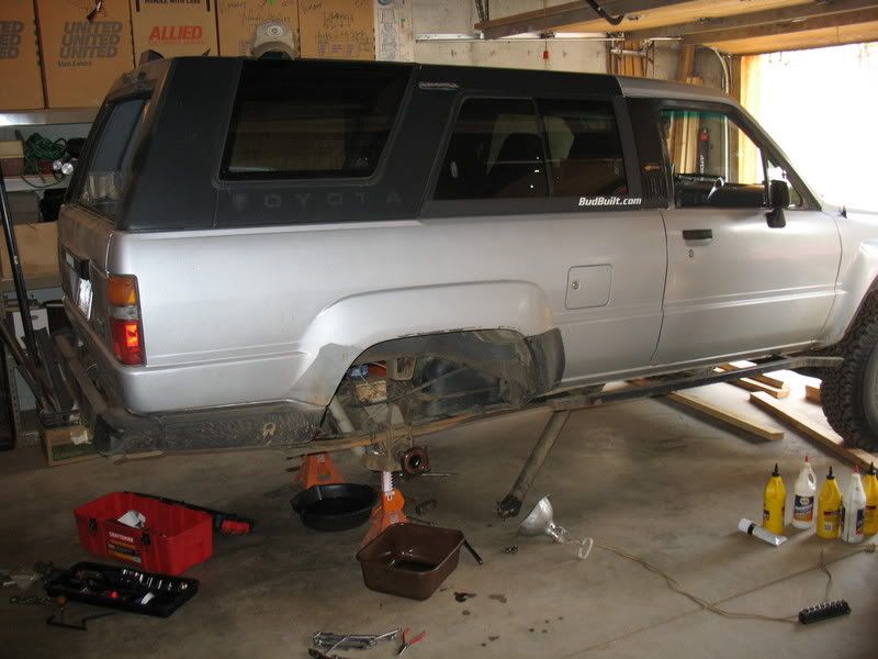
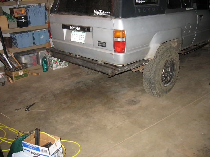
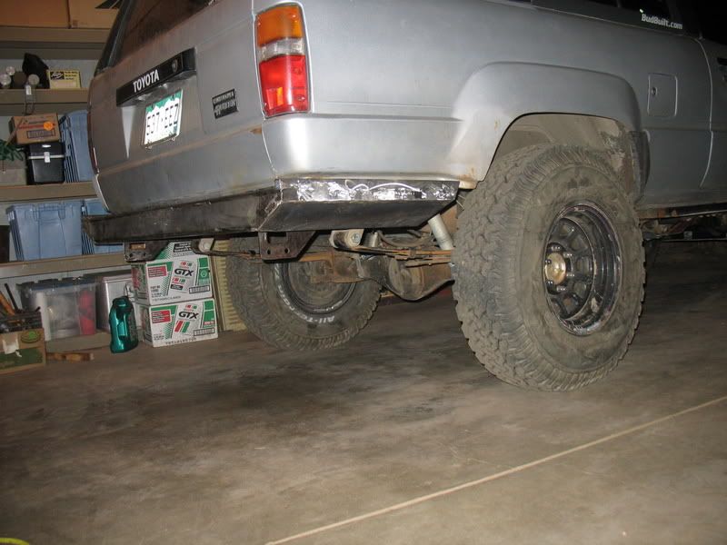
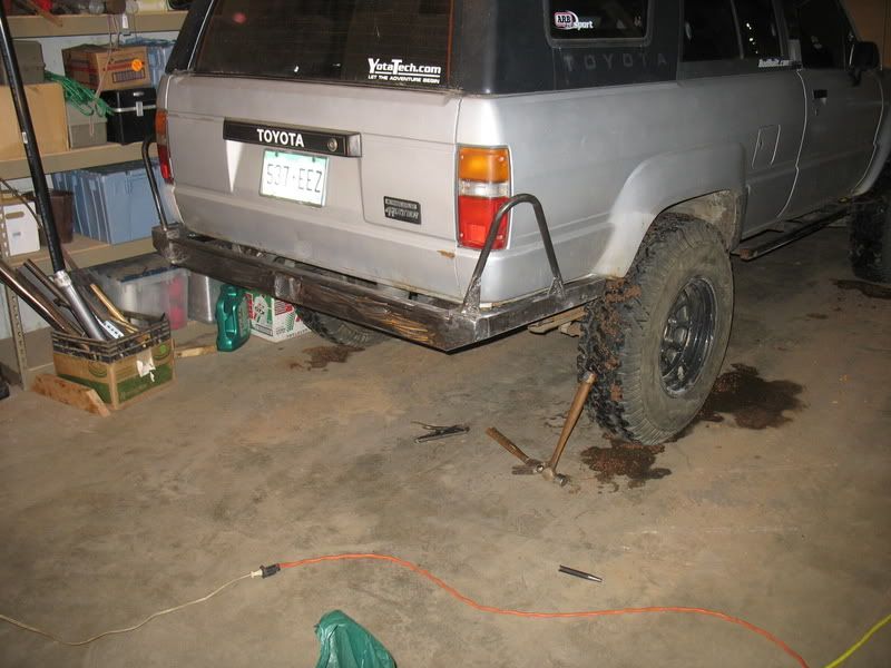
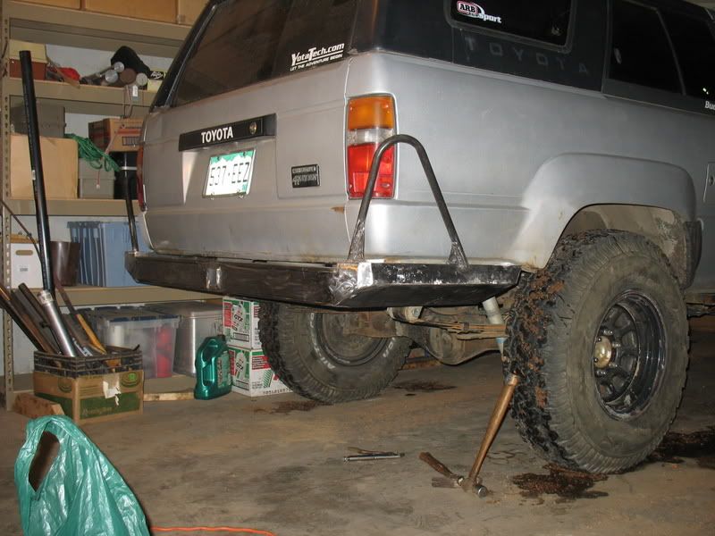
1987 4runner.
292k
22re 5speed.
My mods:
Suspension
Front:
1.5" SDORI Ball joint spacers
OME torsion bars.
Front end relaxed down, so that truck sits at stock height.
Downey Idler Arm Brace
OME Shocks.
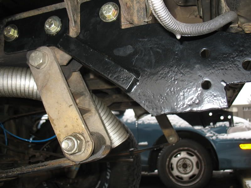
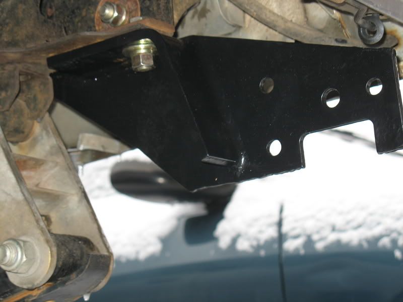
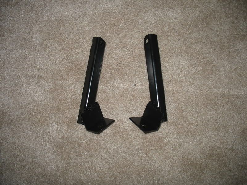
Sonoran Steel Rear IFS crossmember
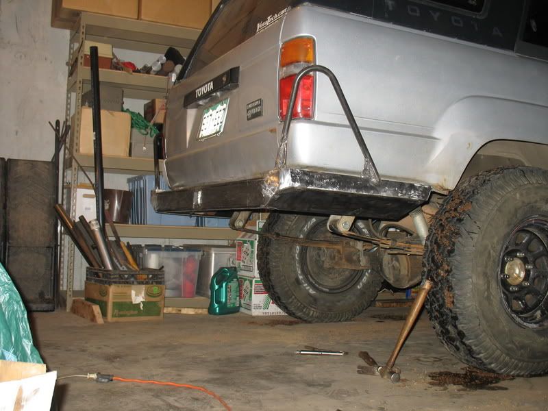
Rear:
Downey 3" springs (crap)
1.5" lift shackles.
Bilstein 5100 Shocks.
Tires:
33x9.50R15 BFG All Terrains.
Wheels:
Currently stock toyota Aluminum
Previous black steelies
(I like the aluminum a lot better)
Armor
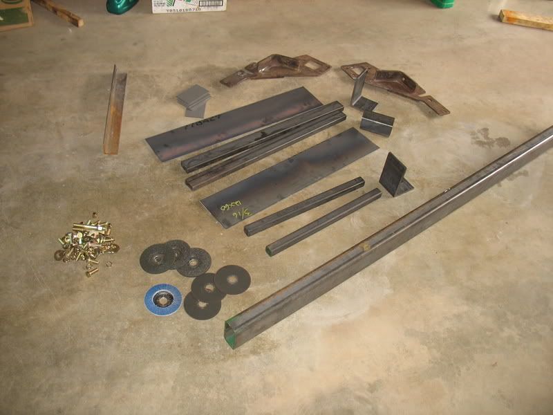
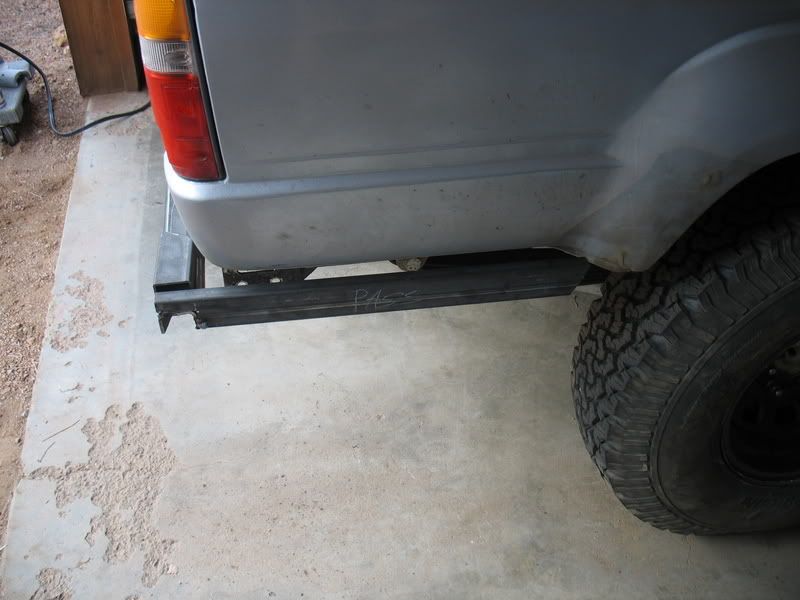
Sliders built by me (need to be replaced as I used steel that was too thin)
Budbuilt Budlight Tranny/Transfer cross member.
Front belly skid built by me: 3/16", angle reinforced steel
ARB Bull Bar
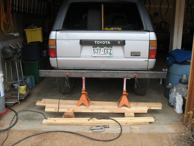
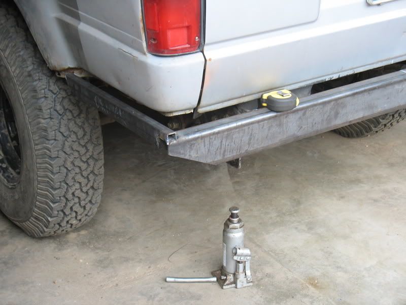
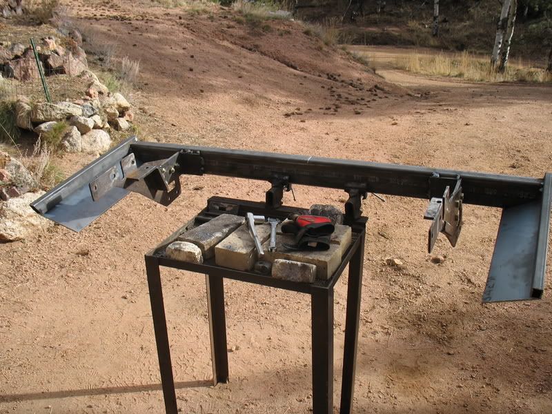
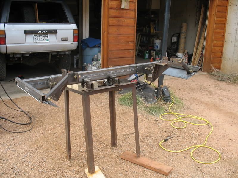
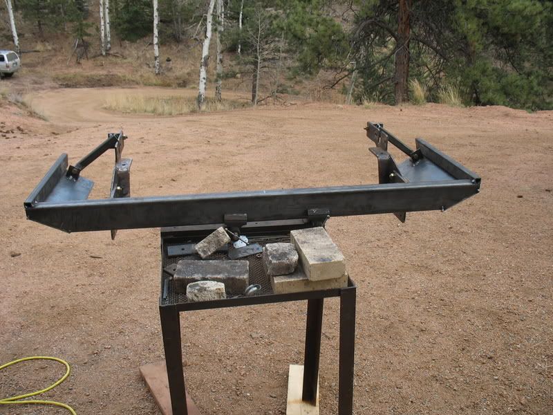
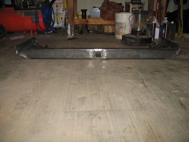
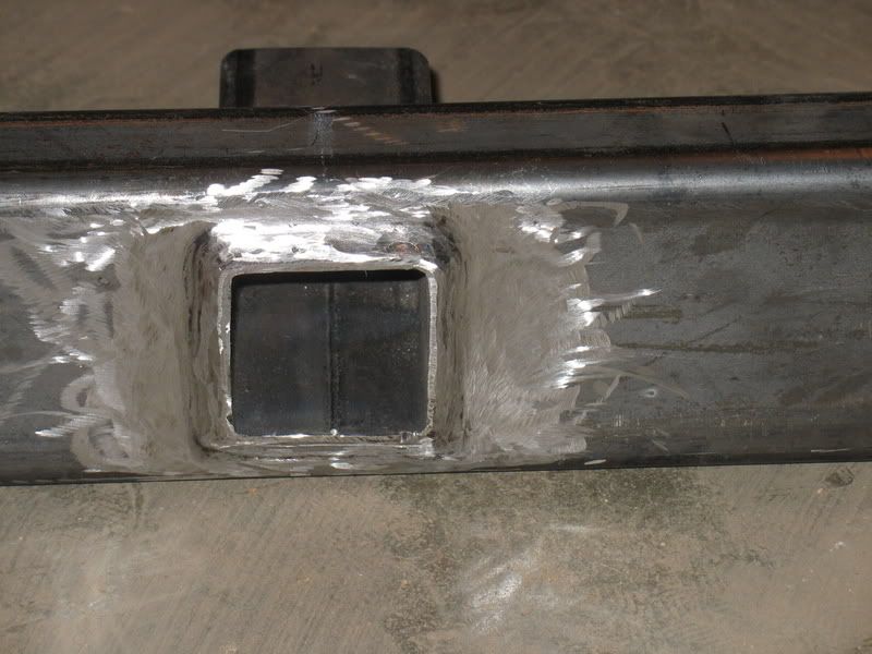
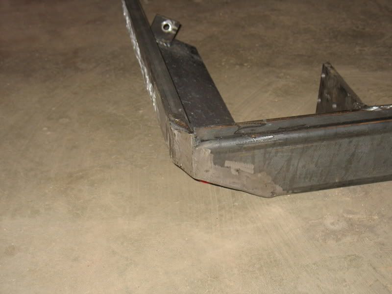
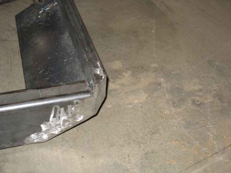
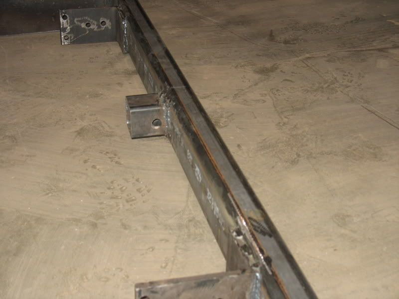
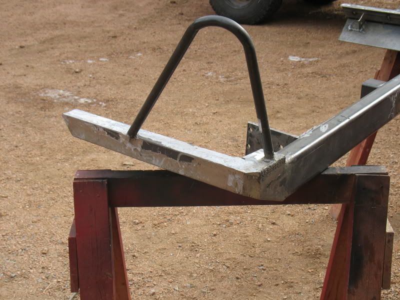
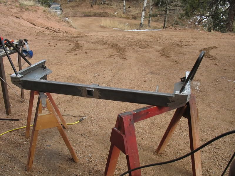
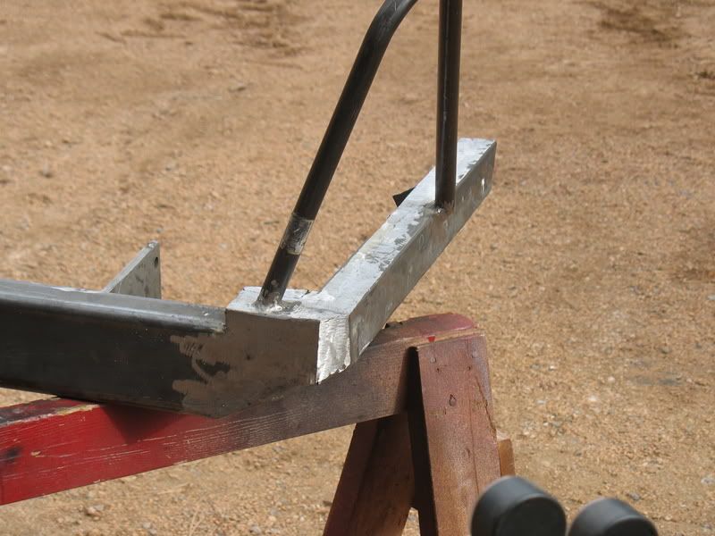
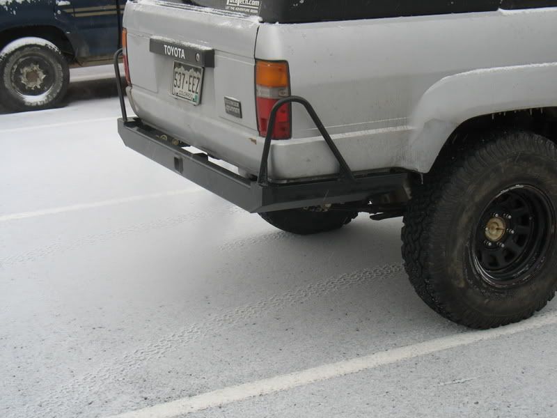
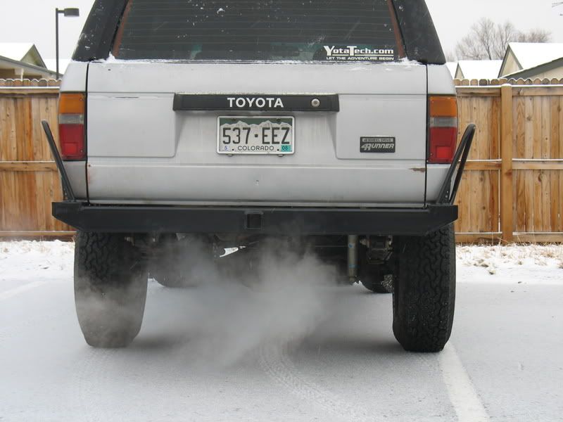
Rear bumper built by me.
Drivetrain
Stock 5speed transmission
Marlin Dual Ultimate Crawler
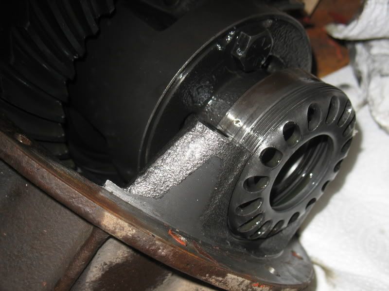
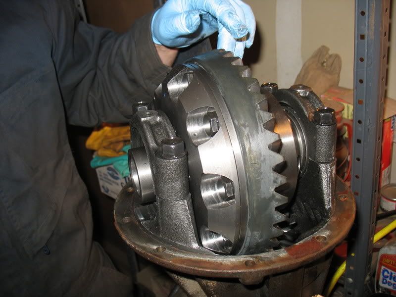
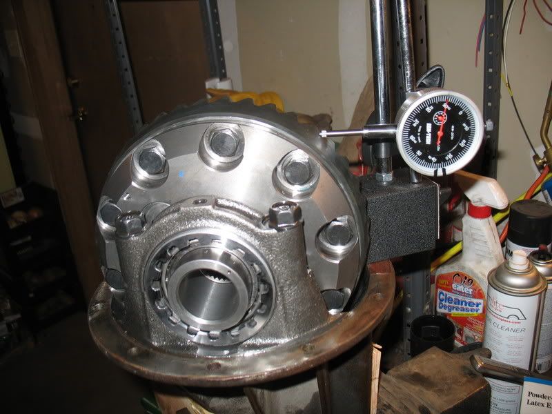
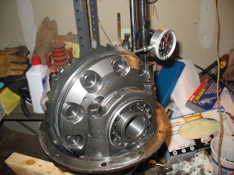
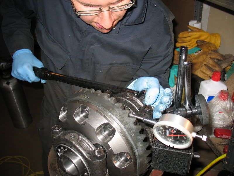
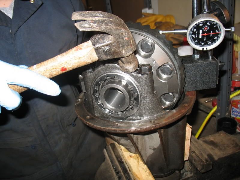
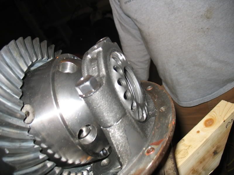
4.88 Precision Gears
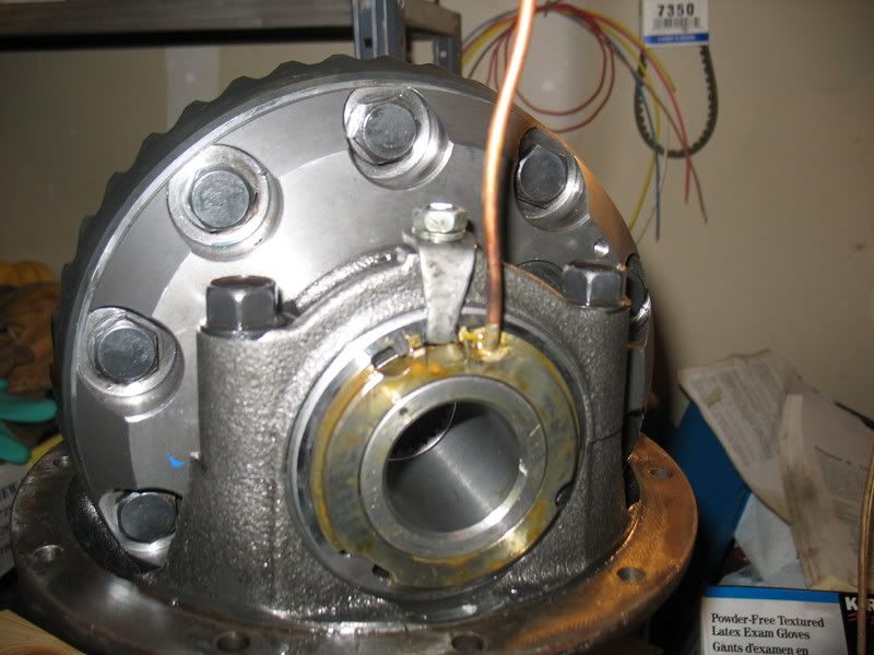
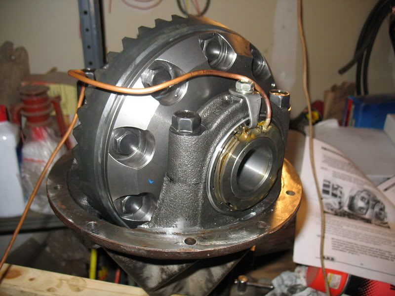
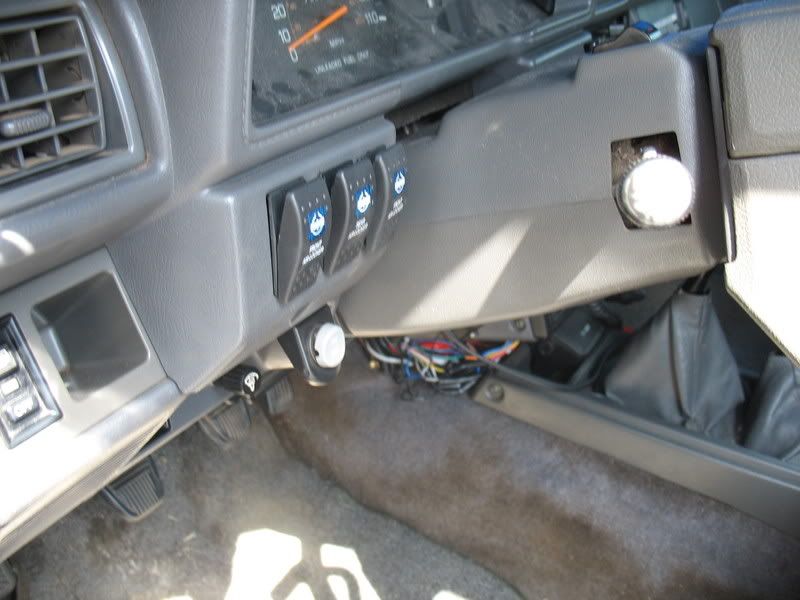
ARB Air Lockers Front/Rear
QuickChange CV mod.
Other
CB
Sirius
Rocklights
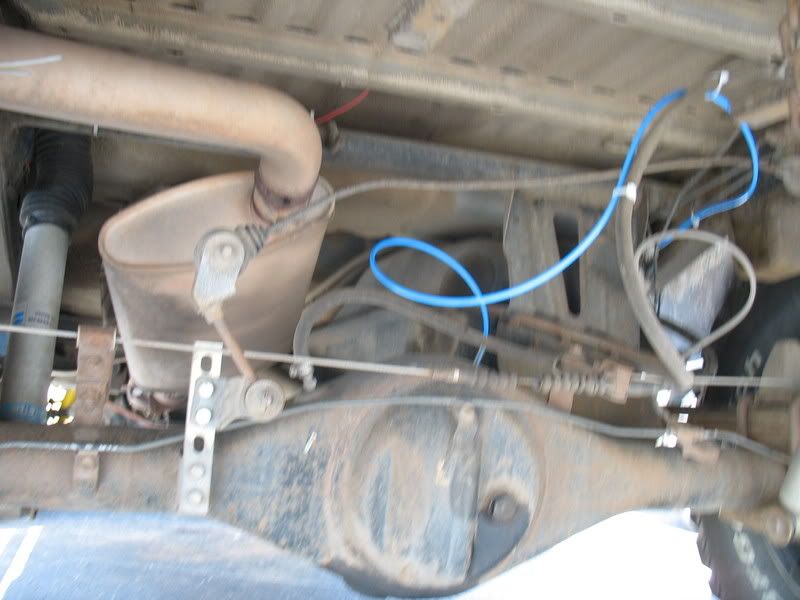
Diffbreathers
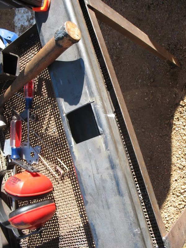
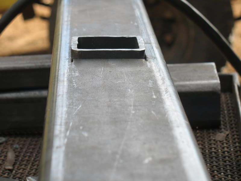
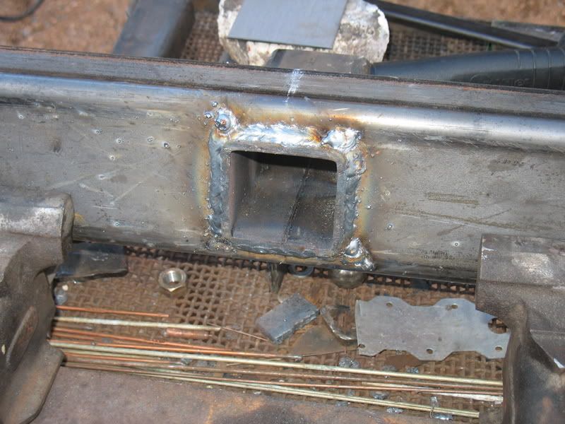
What I plan on doing for the next step is building a rear tool area, which will give me a place to stow all of my tools out of the way, and give me a good base for gear, and maybe someday when I win the lottery, a slide for my engel...
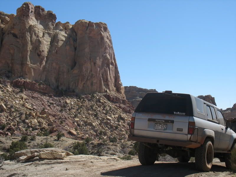
PICS: (I need to get one with the new wheels)

I'm Isaac, live in Gunbarrel Colorado, and I'm new here. I've been around a bit, and LOVE this site, though my wallet hates it!
Figured I'd start my own thread, since, with the near completetion of his trailer, my partner in crime REZARF and I should be up and about doing some "mini" expeditions!
The truck:
1987 4runner.
292k
22re 5speed.
My mods:
Suspension
Front:
1.5" SDORI Ball joint spacers
OME torsion bars.
Front end relaxed down, so that truck sits at stock height.
Downey Idler Arm Brace
OME Shocks.
Sonoran Steel Rear IFS crossmember
Rear:
Downey 3" springs (crap)
1.5" lift shackles.
Bilstein 5100 Shocks.
Tires:
33x9.50R15 BFG All Terrains.
Wheels:
Currently stock toyota Aluminum
Previous black steelies
(I like the aluminum a lot better)
Armor
Sliders built by me (need to be replaced as I used steel that was too thin)
Budbuilt Budlight Tranny/Transfer cross member.
Front belly skid built by me: 3/16", angle reinforced steel
ARB Bull Bar
Rear bumper built by me.
Drivetrain
Stock 5speed transmission
Marlin Dual Ultimate Crawler
4.88 Precision Gears
ARB Air Lockers Front/Rear
QuickChange CV mod.
Other
CB
Sirius
Rocklights
Diffbreathers
What I plan on doing for the next step is building a rear tool area, which will give me a place to stow all of my tools out of the way, and give me a good base for gear, and maybe someday when I win the lottery, a slide for my engel...
PICS: (I need to get one with the new wheels)
Last edited: