Auxbeam 6 Gang on-off Control Switch Panel kit review
Auxbeam asked me if I would be willing to test and review a new switch panel they're offering; I agreed, so they sent me a unit and it arrived the other day. A description of the switch panel on their web site:
https://www.auxbeam.com/qp006238. The panel is priced very nicely considering the features it has, so it seemed worth a serious look.
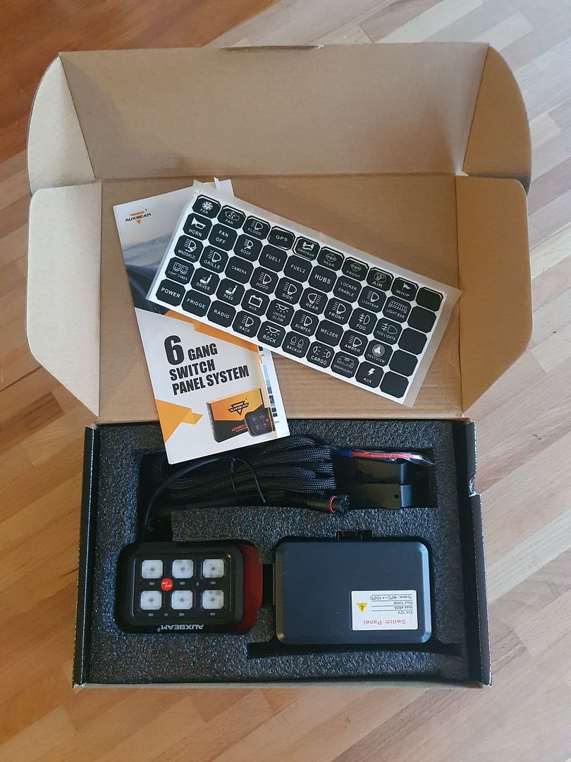
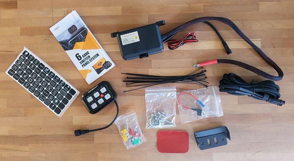
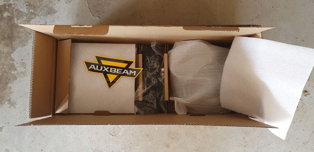
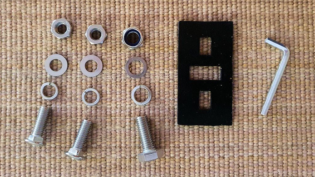
The kit arrived nicely packaged, and includes the switch panel with 45 switch labels, the relay box, an extension to reach between the relay box and the switch panel, a fuse tap for connecting the system to switched power in the Jeep, two methods for mounting the panel (a metal bracket, and a piece of double-sided tape for attaching the panel to a flat surface), some hardware, zip ties and a few extra fuses (a nice touch).
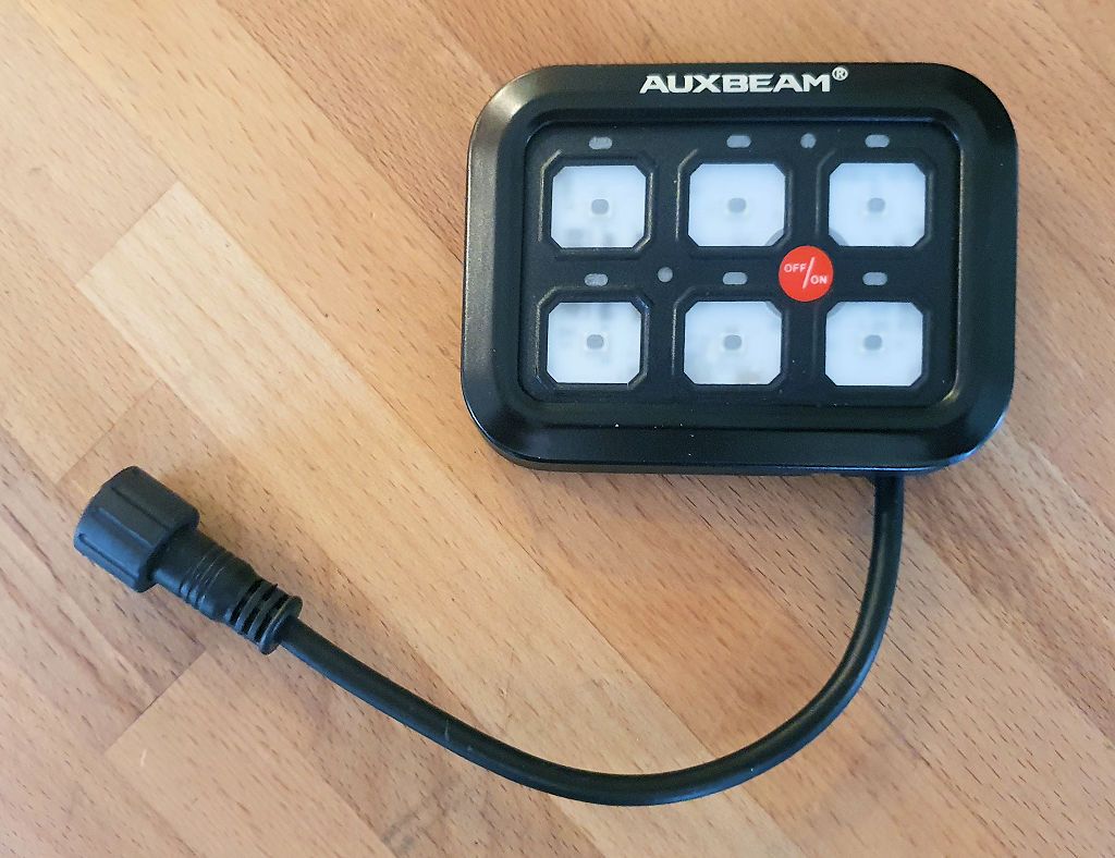
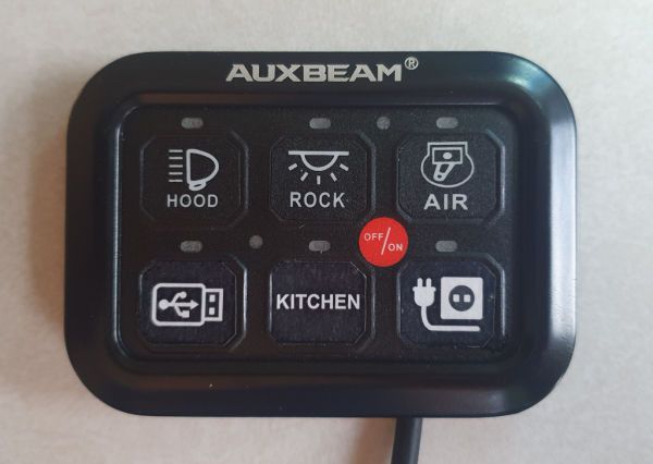
The switch panel has an aluminum housing, six switches, LEDs to illuminate each switch, a main off/on switch (more on that later), and a sensor to auto-dim the switch illumination in low lighting conditions:
A thoughtful detail - the back of the panel has a channel that the wire can be routed through to allow the panel to mount flush on a flat surface. The channel allows the wire to exit the bottom of the panel or the top. The panel measures 3 3/4" wide and 2 5/8" tall.
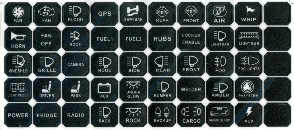
A sheet of 45 self-stick labels are included, and cover most typical electrical applications one might find in a Jeep. Five blank (black) switch labels are also included.
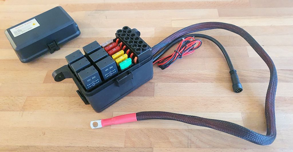
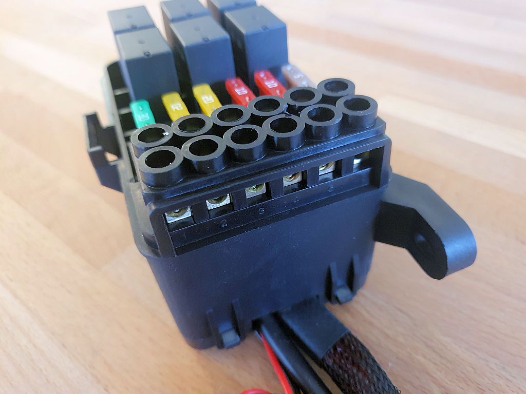
The relay box is very nicely designed. Each circuit has a 30-amp relay, a fuse, and a screw terminal for the positive lead to whatever accessory is being controlled. The negative side is not part of the box, and it doesn't need to be - the ground for an accessory can be done locally to the frame or body or home run to the battery if necessary. A two-foot main power lead with a protective shroud allows mounting the panel up to 2 feet away from the battery, and wires for connecting to switched power and the switch panel are also attached to the box.
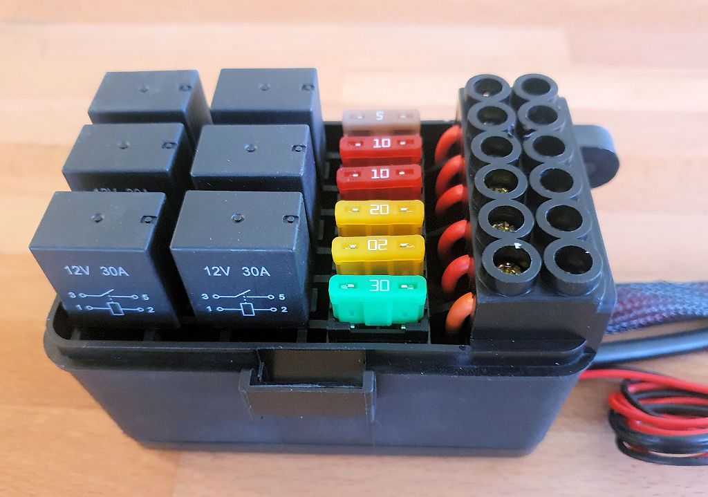
A closer view of the relays and fuses:
The screw terminals are shown in this view. The box has two substantial mounting lugs, one of which is visible in this photo:
I did a quick bench test to verify everything was working properly. I was going to shoot a video showing the bench test but Auxbeam has an excellent 4-minute video on YouTube that does an excellent job at showing how to install the unit. The video shows the installation in a JKU, although most of the steps apply to pretty much any vehicle one might install the system in:
A few comments on the video:
- The fuse tap is shown being installed in fuse position M6, which is the switched power for outlet 1. Fuse M7 can also be used, it's the switched power for outlet 2. These can be configured to be always on, so make sure they're set to switched power in the information center display in the dash.
- There's a view of the relay box at about 30 seconds into the video - the box is shown just setting on the battery and not secured in any way. For this test I installed the box in both a JK and a TJ.
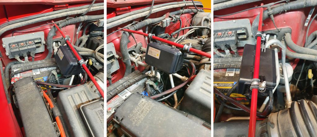
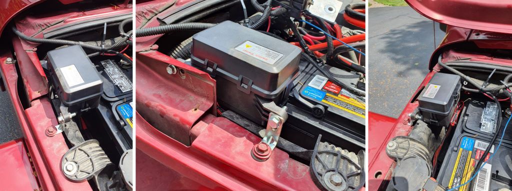
In the JK/JKU, the relay box can mount beside the battery. I used a hardware store angle bracket at the front end of the box. I cut the legs a bit shorter and drilled new holes so the box could mount as low as possible to clear the closed hood. The bracket is secured in place with one of the fender bolts. I then drilled a new hole in the engine compartment side for the back of the box because the spacing of the holes on the box is a little wider than the distance between the fender bolt the bracket is secured to and the factory screw hole in the engine compartment side. The bracket can be seen in the left and center photos; the new hole can be seen in the center photo. The right photo shows that the relay box is not in the way of removing the battery.
Even though there's more air space in a TJ/LJ engine compartment, there isn't a place on the firewall or inner fender that's convenient for mounting the relay box, so I mounted in on the grille brace rod. I used 1/4" insulated wire clamps to go around the rod, and bolts through the clamps and the mounting lugs of the relay box. The rubber of the clamp grips the rod very well when the bolts are tightened. I angled the box down about 45 degrees; if it is mounted horizontally if will stick up far enough to interfere with the closing of the hood.
I believe the main power lead on the relay box is long enough that the box could be mounted in the cockpit on the firewall below the glovebox in a TJ, but I didn't test that.
Once the box is installed and the main power lead is connected to the battery and the switched power leads are connected inside the engine compartment electrical box, the switch panel lead can be routed through the firewall and the panel can be mounted where desired.
If there isn't a label for a particular accessory, additional labels could be created with a drawing program. DIY labels can be printed adhesive-backed white labels from an office supply store, and the surface protected with clear tape. I drew a few, left to right - spotlight, AC inverter power, USB outlet power, sink pump (my Trail Kitchen has a sink with running water), and main power for the kitchen.
I had some Avery 94237 labels on hand, so I printed the ones pictured above. I used matte Scotch tape over them for protection. They worked out pretty well. The top row of labels came with the product, the bottom row I made.
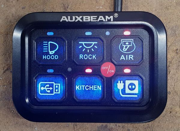
Powered up, the AIR, KITCHEN and A/C INVERTER circuits are on:
My homemade switch labels are a bit brighter with the backlight than the factory switch labels - I like them better that way actually. For my use, I'd probably do all custom labels so everything matched.
A few notes about switch panel operation:
- When the panel is powered up, the backlight is on. Unless it's dark, in which case the backlight dims. The small round thing below/between the Hood and Rock switches in the photos is the light sensor.
- The OFF/ON switch turns everything off - whatever is on at the time switches off. When the OFF/ON switch is pressed again, the system goes back to the state it was in before the first press of the switch. So if three of the circuits are on at the time the OFF/ON switch is first pressed, they go out on first press, and on the second press, those three circuits come back on.
While I haven't yet done a final install and used this panel on the road or the trail, I'm very impressed with the quality of the components and the ease of installation. I think it's very reasonably priced considering the functionality it provides and I can recommend it - it works well, is easy to install and I think it's a good value.
It's available directly from Auxbeam and also can be found on Amazon:
Amazon product ASIN B08RHP4BD9



.jpg)
.jpg)
