Barn Door for JK factory hardtops

jscherb

Expedition Leader
A few months ago Auxbeam asked me to review and edit their draft instructions for a new dual switch panel product. I reviewed the document and sent them some corrections and suggestions. They said they would be sending me a sample of the product to test and review as soon as it was released and it arrived about two weeks ago and they asked me if I would write an article for them covering the use of the dual switch panel system in an overland vehicle. I accepted that assignment and sent them the following article the other day. It's a large article, too large for a single post, so I've broken it up into 5 parts for posting, but other than that what follows is exactly what I sent them. I expect they'll probably post the article on their web site - I've done several articles for them in the past; these can be found at:


For the record: I am not an Auxbeam employee and I receive no compensation for reviewing products and writing articles although I can keep the sample products they send me to review for my own use. I test and review products for several companies because I enjoy trying new things that may enhance my overland experiences and I write articles about these products because I enjoy writing. I hope people find my reviews and articles helpful and I welcome feedback and questions about anything I've written.

I'm posting this article here because it may help people planning the wiring of their overland vehicle regardless of whether they use the Auxbeam product or not - there are wiring considerations for use in an overland vehicle that apply to many switch panel products besides those from Auxbeam and I attempt to cover some of those considerations in this article.

The article on the Auxbeam RA80 X2 Dual Switch System is in the following 5 posts.
 

jscherb

Expedition Leader
Auxbeam’s RA80 X2 Dual Panel Switch System in a Camping/Overland Vehicle
Part 1 - Overland Wiring Options


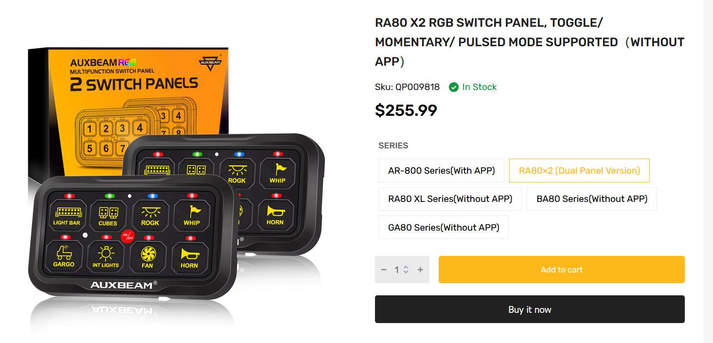
Auxbeam’s RA80 X2 8-gang dual switch panel system can be very useful for a vehicle configured for camping and overlanding - one switch panel can go within the driver's reach for accessories like driving lights, and the second panel can go in the back to be easily accessible at the camp site (https://auxbeam.com/products/qp009818).

DualPanelPage_sTX4rbhj9UZz8tzeAp5nUy.jpg


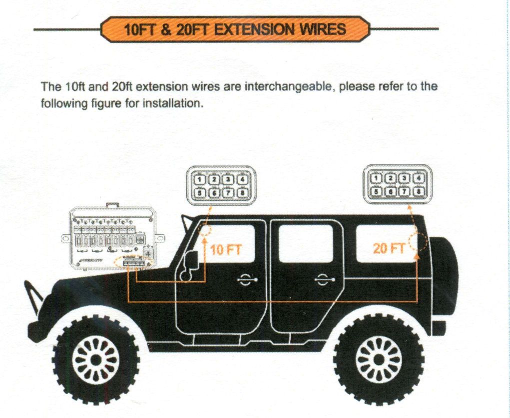
DualPanelIllustration_c2raKPmnVHjtWnDsaK5pJF.jpg


Using dual panels to control driving and campsite accessories does bring up additional wiring considerations. Normally, the system would be powered by a switched circuit in the vehicle and therefore only powered when the ignition is switched on, but it is not a good idea to require the ignition to be switched on whenever accessories controlled by the switch panel need to be used at the campsite - at best, it's inconvenient and at worst leaving the ignition switched on at the campsite could result in the battery being drained. This article will cover wiring considerations and some installation details for a typical camping/overland vehicle to avoid unnecessary battery drain at the campsite.
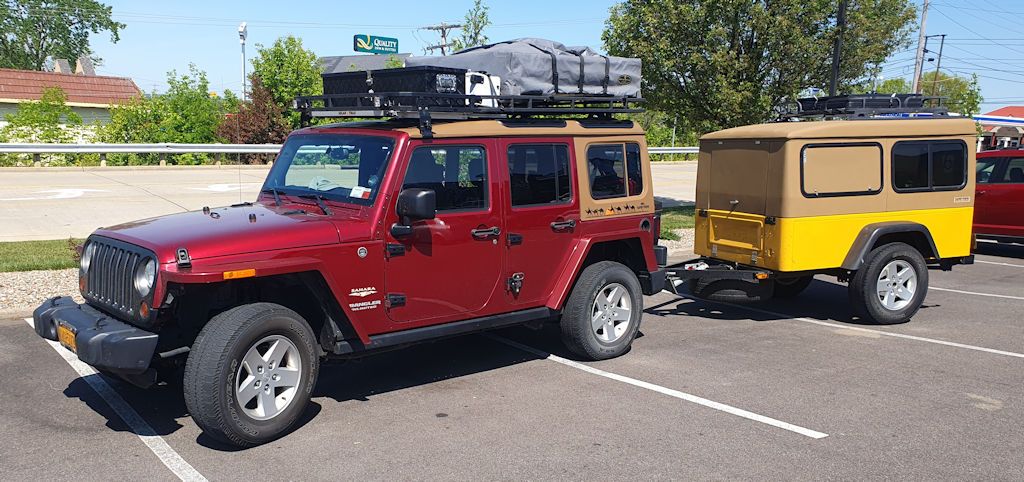
The vehicle being used for this article is a 2013 Jeep Wrangler Unlimited. In front it has Auxbeam driving lights mounted on the roof rack and in the cargo area a MORryde Trail Kitchen is installed. One of the switch panels will be mounted up front near the driver and the second will be mounted in the back by the Trail Kitchen.

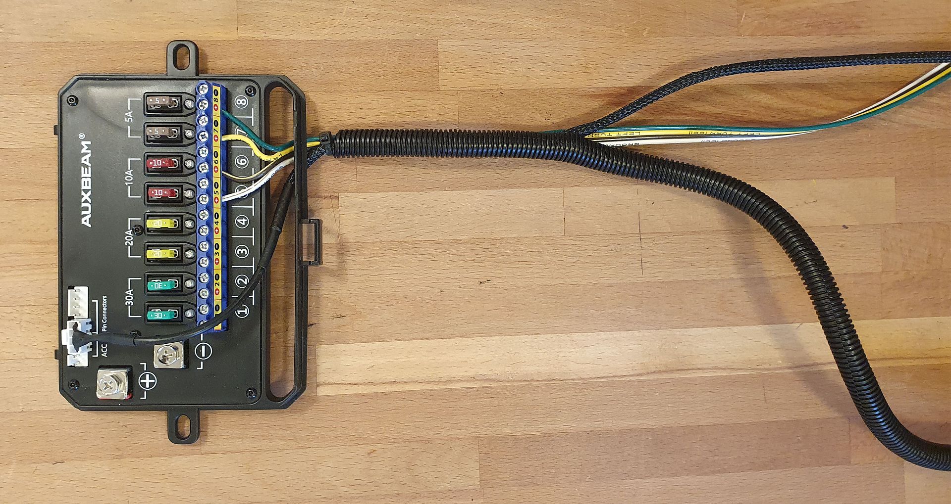
The first thing to know in planning your installation is that the two switch panels work in parallel - there are 8 circuits in the RA80 X2 control box and each panel has 8 switches. Switch 1 on both panels controls circuit 1 in the control box, so if driving lights are connected to circuit 1, switch 1 on either panel with operate those lights. You have 8 circuits for accessories, and all of those 8 circuits can be controlled from either panel.

Powering the RA80 X2 Control Box

With a typical single switch panel system, it is normally recommended that the control box be powered by a switched circuit in the vehicle. A switched circuit is one that's powered on when the ignition switch is in the on position, and powered off when the ignition switch is off. Powering the panel with a switched circuit ensures that the switch system and its connected accessories won't drain the battery when the vehicle isn't running.

Considerations may be different for a dual switch panel system - if the second panel is mounted in the back of the vehicle for use at the campsite, for example to control campsite lights mounted to the roof rack, you wouldn't want to have the ignition switch on all the time at the campsite - you'd want the switch system to operate without the ignition switch having to be on. Let's review three wiring options...


Wiring Option 1 - Switched Circuit in Vehicle (Per Auxbeam Instructions)

The instructions recommend powering the control box from a switched circuit in the vehicle, which means that any accessories connected to the system will only be able to operate when the vehicle is running or the ignition switch is turned on. For accessories used when driving, like driving lights, that's not a problem, because the switched circuit will be on.

But if the second switch panel is used in the back of the vehicle to control campsite accessories, you would either have to have the vehicle running or have the ignition switch turned on at the campsite for those accessories to be used. Running the engine all the time probably isn't a good idea, and having the ignition switch turned on all the time at the campsite isn't the best idea either - the vehicle circuits that are powered when the ignition switch is on will be an unnecessary drain on the battery and could lead to a discharged battery overnight.


Wiring Option 2 - Driving/Campsite Switch

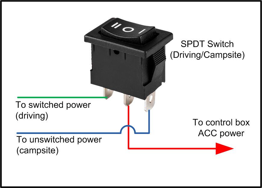
A way to use the switch system with the ignition switched off is to install a switch to control the power to the control box. In the "driving" position, the switch would power the control box from a switched circuit and in the "campsite" position, the switch would power the control box from an unswitched circuit. What’s good about this is for normal driving, any accessories controlled by the system will be powered off when the vehicle is not running, so they can’t be left on accidentally and drain the battery. And at the camp site, accessories can be used without the need for the ignition switch to be on.

CampsiteSwitch1.jpg


The switch is a single pole double throw (SPDT). Optionally it could be an SPDT Center Off switch, in which case the center position would cut all power to the control box off.

The benefit of using the switch system in "campsite mode" is that the vehicle circuits that are powered by the ignition switch being in the on position will not be powered, which eliminates some drain on the battery while sitting at the campsite. Typically, you wouldn't be using "driving accessories" at the campsite such as driving lights, you would only be using campsite accessories, perhaps LED campsite lights mounted to the roof rack, so power drain would be limited to just the campsite accessories plus the small power draw that the switch control box requires.

But forgetting to turn off campsite mode when you no longer need it could cause your vehicle battery to discharge, so it might be a good idea to have a reminder that the campsite mode is on. This can be done with a double pole double throw (DPDT) switch and a 12v LED indicator light; wired as per the next diagram, the LED will light whenever campsite mode is on and will serve as a reminder to turn off campsite mode when it is no longer needed.
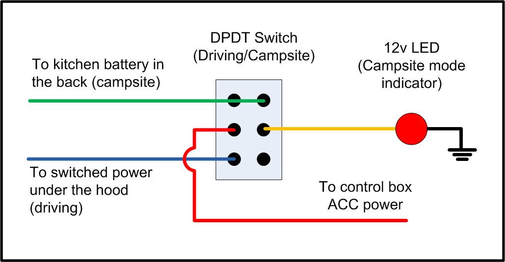
CampsiteSwitch3.jpg


The switch control box draws about 75ma. with both switch panels connected and all circuits turned on. That's a negligible drain on the main vehicle battery just for the control box, but to that the drain of the accessories switched on must be added. For example, if an accessory that draws 10 amps is to be switched on, it may not be a good idea to power that from the main vehicle battery when the vehicle isn't running - it may drain the battery past the point of being able to start the vehicle the next morning. Which leads us to the third option...


Wiring Option 3 - Vehicle with two batteries

Our test Wrangler has two batteries - the standard vehicle battery up front, and a fridge/kitchen battery in the back. In this vehicle, we'll use the driving/campsite switch described above to power the switch control box, but the campsite accessories in the back can be powered either from the main vehicle battery or from the kitchen battery. Powering campsite accessories from the kitchen battery will greatly reduce the load on the main vehicle battery, ensuring that the main battery will have enough power to start the vehicle when it’s time to leave the campsite. More on this wiring later.

The test Wrangler has a refrigerator in the back that’s powered from the fridge/kitchen battery. Since the fridge typically is used from the moment food is loaded before an expedition until returning home, there’s no real need to control its power using the switch panels. The kitchen battery is mounted in the back right next to the fridge, and the fridge has a convenient power switch on its front panel, so it’s directly connected to the kitchen battery. Only accessories which will be turned on/turned off at the campsite will be controlled through the switch panel system.
 

jscherb

Expedition Leader
Auxbeam’s RA80 X2 Dual Panel Switch System in a Camping/Overland Vehicle
Part 2: Mounting the RA80 X2 control box and routing wires in a JK/JKU


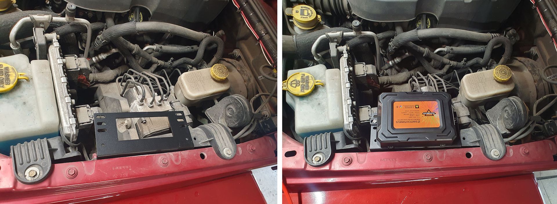
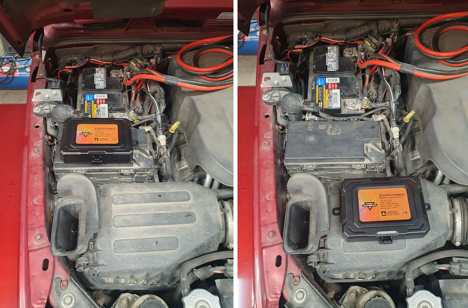
Modern engine bays are very cramped and often don’t provide many good locations for mounting things like the Auxbeam control box. In our test 2013 Wrangler, there are several possible locations. The best location is probably to the inner fender on the driver’s side – the supplied angle bracket mount can be bolted to the inner fender (left photo). Drilling the inner fender is required. The drawback of using this mounting location is that the supplied battery cables are too short to reach from this location to the battery.

ControlBoxMountingDrv.jpg


There are two mounting options on the passenger - mounting the box to the top of the TIPM (Jeep’s name for the underhood fuse/electronics box, left photo below), or to the top of the air filter housing (right photo). The supplied battery cables will reach to both of those locations. If you do decide to install in either of these locations, be sure to provide enough slack in your accessory wiring to be able to open the TIPM or the air filter housing when needed.

ControlBoxMountingPass.jpg


Routing wires to the back of the vehicle

For this installation four of the circuits are going to be dedicated to driving accessories and four to campsite accessories. The second switch panel will be mounted in the back of the Jeep, and to power accessories back there a four-conductor wire will be run along with the switch panel wire. 16/18-gauge 4-conductor trailer wire will be used and protected along with the switch panel cable in 3/8” diameter split wire loom to make routing the wires easier and more professional looking. The switch panel cable and the 4-conductor cable both fit nicely in the wiring loom:

WiringLoomRear.jpg


One of the wires will be for each of the four circuits dedicated to the rear accessories, and ground connections will be made to the Jeep body in the back. Optionally a separate large gauge ground wire could be run from the back of the vehicle to the battery in the engine bay for a better ground connection - accessories in the back would be grounded to that wire.

The four-conductor trailer wire is adequate for most low-power devices such as LED lights, but higher-powered accessories will likely require larger gauge wire to be run. In the case of this Jeep, however, this gauge wire will be adequate because higher power accessories in the back will be run from the kitchen battery, and the smaller gauge wire will control a relay to switch the kitchen battery power to that accessory as per option 3 above.

The control cables from both switch panels and the wiring for the accessories out back will need to be routed out of the engine bay and into the interior of the vehicle. Other vehicles will be different; what follows is one way to do it in a JK Wrangler. The JK has a large hole in the firewall just behind the battery, its location is marked by the yellow square in the left photo below. To access this hole, pull the plastic cable straps (arrows) off the studs in the firewall and pull back the cable and the firewall insulation. The hole is covered with a piece of soft black self-stick plastic that can be peeled back.

JKWiringFirewall.jpg


Once the insulation and self-stick plastic are out of the way, cut a hole in the insulation on the inside of the firewall that’s big enough to push the wires through. The insulation is backed with plastic, so you’ll need to cut a hole through the plastic. When the hole is large enough, push the wire through from the engine bay side; when enough has been pushed through you can reach under the dash and pull it through from that side. Pull the wire through until most of the wire is inside the Jeep.

With the wire inside the Jeep, the control cable for the front switch panel can be routed under the dash to wherever you plan to mount that panel, and the control cable and wires for the rear can be routed under the carpet alongside the door openings.
 

jscherb

Expedition Leader
Auxbeam’s RA80 X2 Dual Panel Switch System in a Camping/Overland Vehicle
Part 3: Mounting the RA80 X2 switch panels


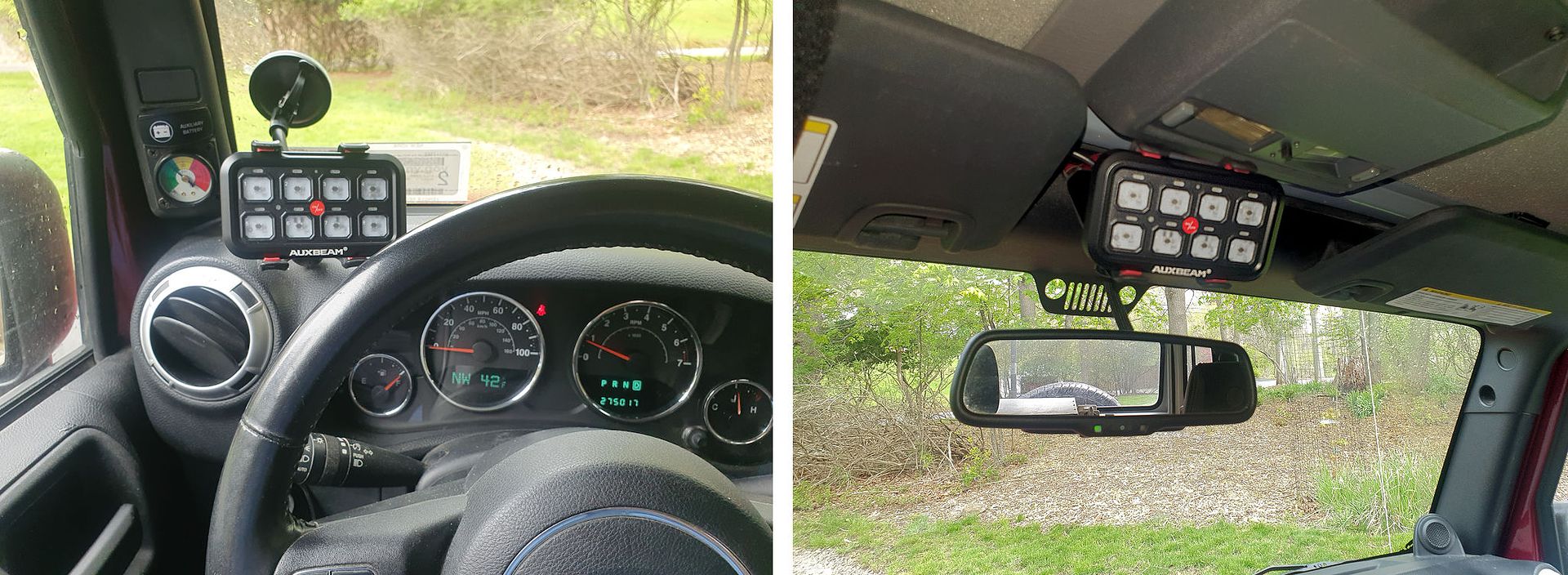
Switch panels can be mounted up front using a phone/GPS clip mount. These can be a good choice for mounting near the driver because modern vehicles don’t offer much empty dash real estate and using these types of mounts, the panel can be installed in several places, usually without drilling.

MountingLocationsFront.jpg


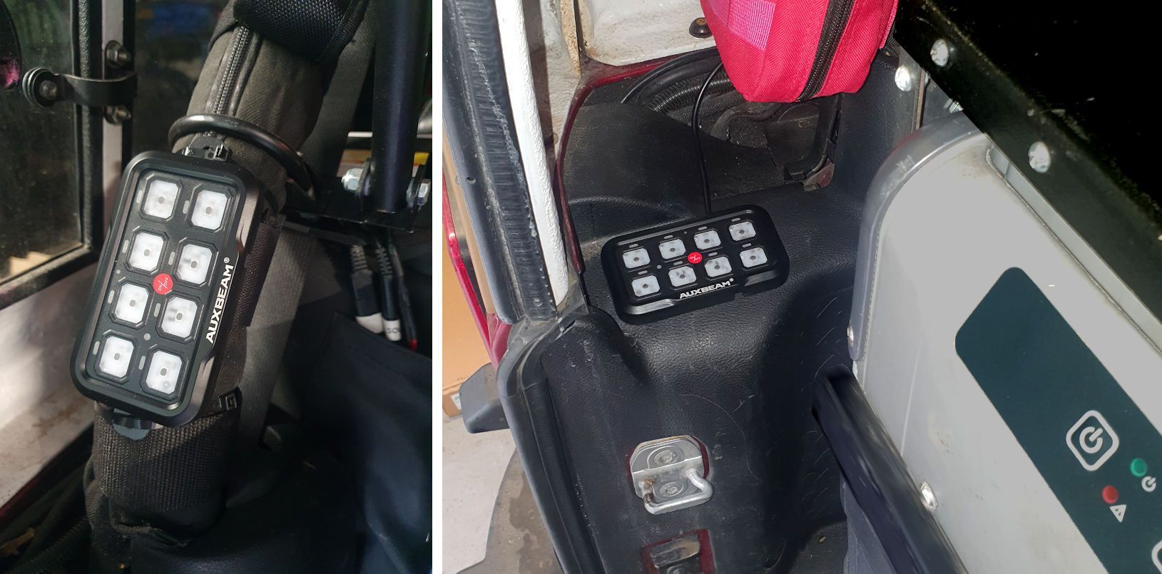
A great place to mount the switch panel in the rear of a Wrangler is on the roll bar. This uses the supplied mounting bar and it’s held to the roll bar with zip ties. In the rear of the Wrangler the panel can also be mounted on the inner fender trim panel (right photo). It’s mounted using double-sided tape to avoid the need to drill holes in the trim panel.

MountingLocationsRear.jpg


Powering accessories in the back

The four wires that were run from the control box up front to the rear of the vehicle can directly control accessories in the back – for example the campsite lights installed on the roof rack can be connected to one of those wires and they’ll be controlled from the circuit that wire is connected to in the control box, and powered from the main vehicle battery.

Since the test vehicle for this article has a kitchen battery in the rear, accessories can optionally be powered from that battery, which is a good idea for campsite accessories – powering those from the kitchen battery will reduce the load on the main vehicle battery. As much as possible and practical, it’s a good idea to reduce the load on the main battery while at the campsite – we don’t want the main battery to discharge to the point where it won’t start the vehicle when it’s time to leave the campsite.

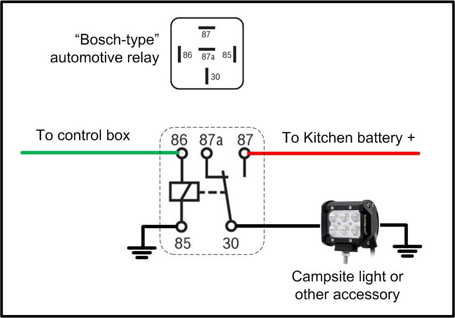
Powering an accessory from the kitchen battery is accomplished with a relay:

RelayWiring.jpg


The green wire is one of those routed from a circuit in the control box in the engine bay and it powers the relay when that circuit is switched on. The red wire goes to the positive terminal of the kitchen battery, and through the relay the kitchen battery powers the accessory, in this case a campsite light. The relay is mounted in the back, near the kitchen battery.

The relay in the diagram above is a standard Bosch type automotive relay. These draw about 175ma. when activated, which isn’t much, but there are relays that draw about 20ma. when activated, and solid-state relays that draw 5ma., so if you’re really trying to minimize drain on the main battery, lower-power relays are available. But 175ma. isn’t much to worry about.
 

jscherb

Expedition Leader
Auxbeam’s RA80 X2 Dual Panel Switch System in a Camping/Overland Vehicle
Part 4: Additional features


The main focus of this article is wiring to minimize power drain in an overland/camping vehicle, so this article won’t cover some of the additional features of the switch system in detail. Special features include the ability to change the color of the switch panel backlight (perhaps to match the color of your dash lights), and the ability to set the mode of each switch.

The default mode for each switch is on/off - one press turns the circuit on and a second press turns it off, but switches also can be set for momentary operation (circuit is on only while the switch is pressed) and pulsed mode - one press turns on the circuit, which will blink the output, and a second press turns it off. Pulsed mode can turn a light into a flasher, which may be useful for first responders. Those switch modes are demonstrated in this video:


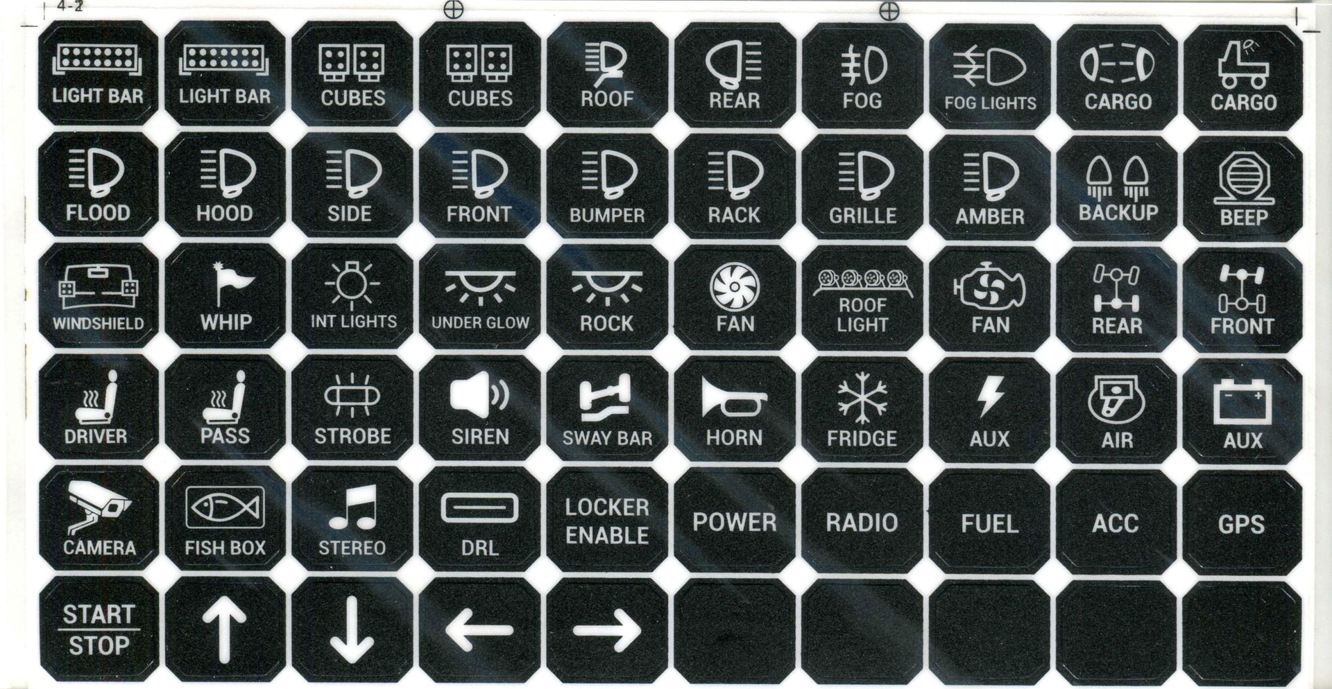
Auxbeam supplies two identical sets of 60 stick-on labels for the switches (one set for each switch panel) and there’s a pretty good selection:

SwitchLabels_eKGLeevmKbth8czNDiUBsy.jpg


They also offer a set of 120 additional stickers that include more labels and graphics (https://auxbeam.com/products/qp009375) so if you don’t find what you need check those out.

But if you do have accessories for which there are no labels, see Auxbeam’s web site for an article on how to make your own custom switch labels: https://auxbeam.com/blogs/how-to-choose/making-custom-switch-labels-for-your-auxbeam-switch-pane


Auxbeam’s RA80 X2 Dual Panel Switch System in a Camping/Overland Vehicle
Summary


The driving/campsite switch and optionally powering campsite accessories from a second fridge/kitchen battery can greatly reduce the load on the main vehicle battery. This can be important out in the wild; powering accessories off the main battery and/or requiring the ignition switch to be in the on position to use campsite accessories risks draining the main battery while camping; not being able to start the vehicle when it’s time to leave the wilderness isn’t a position anyone should be in, so plan your installation with your use of electrical campsite accessories carefully and enjoy being in the wild (and getting back out!).

The system is engineered and manufactured to Auxbeam’s usual high quality standards and is an excellent value for those needing the convenience of dual switch panels plus the additional capabilities that the system offers.
 

jscherb

Expedition Leader
Auxbeam’s RA80 X2 Dual Panel Switch System in a Camping/Overland Vehicle
Part 5: Taking it further: an ultimate overland/camping electrical implementation


This article has focused on minimizing the drain on the main vehicle battery to ensure that the vehicle can be started after days of camping. If the camping setup includes a fridge, it’s really a good idea to power that with a separate battery as described above to reduce the drain on the main vehicle battery.

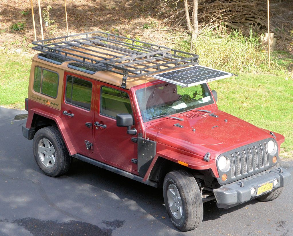
Our test Wrangler includes several features not mentioned above which allow it to remain in the wild indefinitely. A solar panel is stored under the roof rack for travel, and slides out from under the rack at the campsite. It’s a 100-watt panel which puts out 6 amps in full sun, and that’s been proven in the wild to be able to keep the kitchen battery charged with the fridge and other campsite accessories in use.

SolarDeployed1.jpg


Additionally, the kitchen battery is wired so that when the vehicle is running, the alternator charges the kitchen battery, so while overlanding from one campsite to the next, if the kitchen battery isn’t fully charged when leaving the first campsite, it will be fully charged by the time the next night’s campsite is reached.

With the total wiring configuration in this vehicle, the only drain on the main battery at the campsite is the very minimal 75ma. that the control panel draws. All of the campsite accessories controlled by the switch system are powered from the kitchen battery and the kitchen battery is kept charged by the solar panel, so this Wrangler can stay “off the grid” indefinitely without worrying about electrical power.

Not every vehicle used for camping or overlanding needs the comprehensive overland electrical system that this Wrangler has, but by using the wiring techniques for the Auxbeam system that are described in this article you plan your installation to minimize the drain on the main battery while at the campsite.
 
And one last quick sewing project...

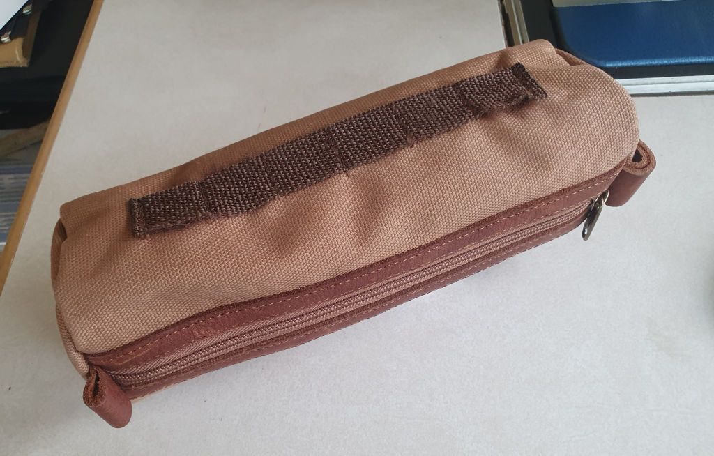
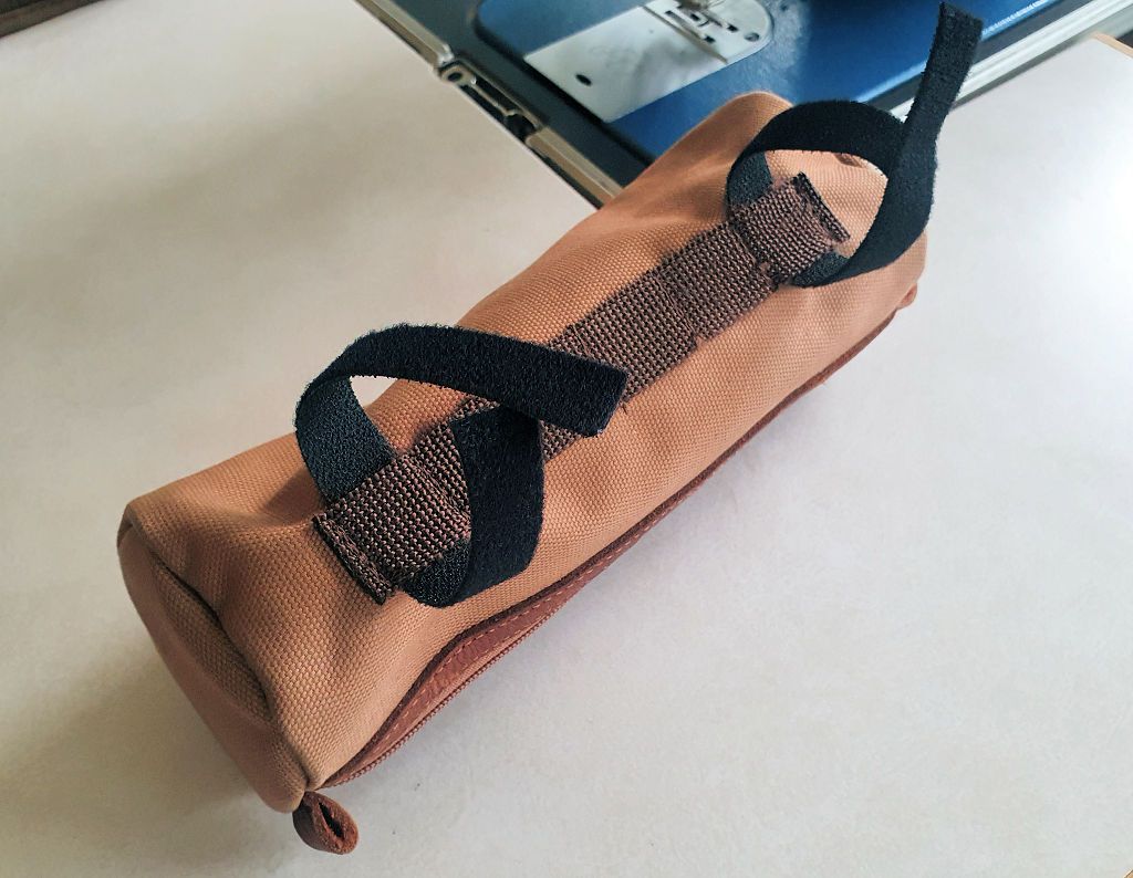
I found this bag at a Duluth trading store about two years ago. It was part of their "Firehose" canvas line and advertised as a toiletries bag but it seemed like a good candidate to convert to Molle or perhaps a roll bar mount. I looked for it today on the Duluth site and couldn't find it so maybe it's discontinued, but the concept in the thread can apply to other bags as well.

DuluthFirehoseToiletriesBag.jpg


Because of its shape, it doesn't lend itself too well to Molle straps, so I came up with a different mounting method for it. I sewed a strip of webbing to the back, similar to a Molle strip:

DuluthBackStrap.jpg


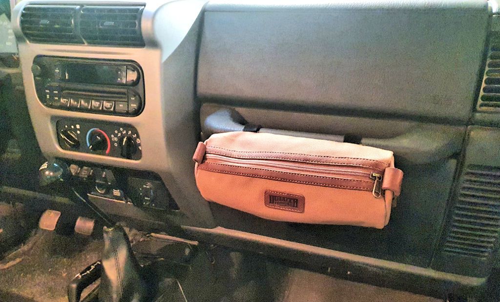
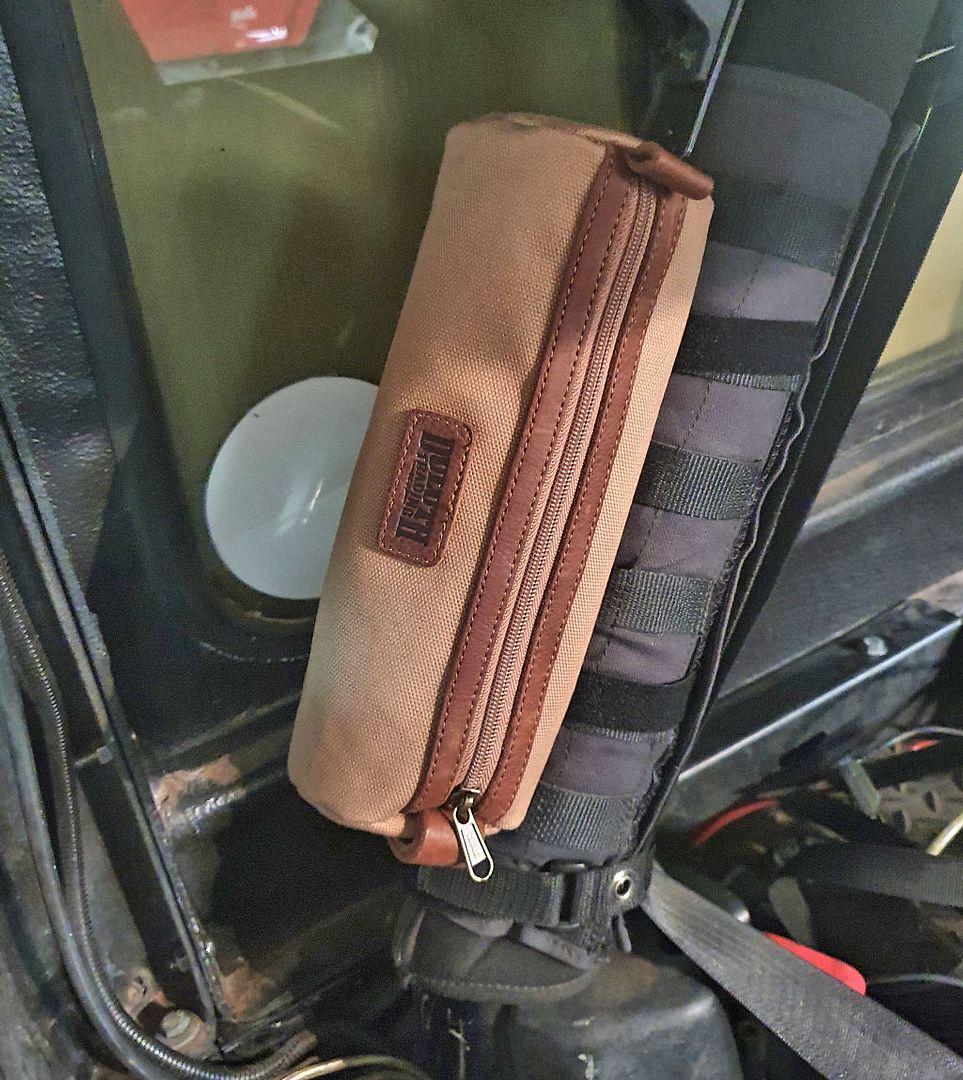
Lengths of Velcro One-Wrap can be threaded through the strap to hang in on a roll bar, or on a grab bar:

DuluthOneWrap.jpg


DuluthOnGrabBar.jpg


All of the simple sewing projects I've posted recently are easy enough for a beginner at sewing, they're quick to do and can be useful in a Jeep. And a good start towards more complicated sewing projects ;)

On the roll bar:

DuluthOnRollBar.jpg


In this series of posts I was trying to show some simple things you could do with a sewing machine that could add value to outfitting your Jeep. Even if you don't sew or have a sewing machine, I'm sure you know someone that does, and all of these are very simple projects that you could ask your mother to do for you (she probably has a sewing machine?) I'll stop with the sewing posts now.
Wow. You do really nice original work and smart junkyard crawling. And I thought I was good making curtains with grommets... You might like the Sailright company in Indiana. They have great supplies and how-to videos.
 
Auxbeam’s RA80 X2 Dual Panel Switch System in a Camping/Overland Vehicle
Part 5: Taking it further: an ultimate overland/camping electrical implementation


This article has focused on minimizing the drain on the main vehicle battery to ensure that the vehicle can be started after days of camping. If the camping setup includes a fridge, it’s really a good idea to power that with a separate battery as described above to reduce the drain on the main vehicle battery.

Our test Wrangler includes several features not mentioned above which allow it to remain in the wild indefinitely. A solar panel is stored under the roof rack for travel, and slides out from under the rack at the campsite. It’s a 100-watt panel which puts out 6 amps in full sun, and that’s been proven in the wild to be able to keep the kitchen battery charged with the fridge and other campsite accessories in use.

SolarDeployed1.jpg


Additionally, the kitchen battery is wired so that when the vehicle is running, the alternator charges the kitchen battery, so while overlanding from one campsite to the next, if the kitchen battery isn’t fully charged when leaving the first campsite, it will be fully charged by the time the next night’s campsite is reached.

With the total wiring configuration in this vehicle, the only drain on the main battery at the campsite is the very minimal 75ma. that the control panel draws. All of the campsite accessories controlled by the switch system are powered from the kitchen battery and the kitchen battery is kept charged by the solar panel, so this Wrangler can stay “off the grid” indefinitely without worrying about electrical power.

Not every vehicle used for camping or overlanding needs the comprehensive overland electrical system that this Wrangler has, but by using the wiring techniques for the Auxbeam system that are described in this article you plan your installation to minimize the drain on the main battery while at the campsite.
I looked all over for a splitter cable to switch between shore AC and AUX DC cylinder plug on a simple old setup for an Engel. Or some kind of A-B box. I decided to build one but now don't have to because the newer Engel models switch automatically.
 

jscherb

Expedition Leader
Wow. You do really nice original work and smart junkyard crawling. And I thought I was good making curtains with grommets... You might like the Sailright company in Indiana. They have great supplies and how-to videos.
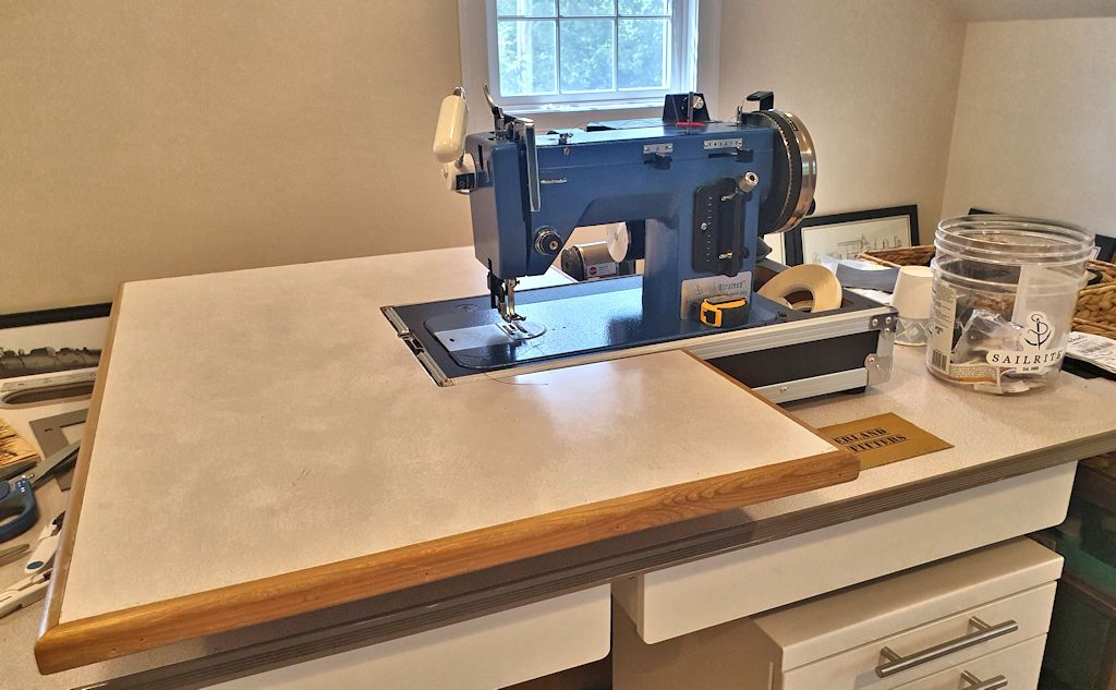
Thank you for the kind words. Yes, I'm well acquainted with Sailrite, my main sewing machine is a Sailrite Ultrafeed LSZ-1 with the servo motor and Monster II balance wheel options - with those options I can sew very thick layers of heavy fabric at extremely slow speeds. It has no trouble with multiple layers of factory soft top fabric including sewing through plastic stiffeners or multiple layers of leather. It's my second favorite power tool :).

UltraFeedLSZ-1.jpg
 

jscherb

Expedition Leader
After testing the Auxbeam RA80 X2 Dual Switch Panel System and writing the article for Auxbeam on how it might be used in an overland vehicle, I offered to write a document describing a potential switch system product that would be even better suited to an overland vehicle. I drafted that document and while I was at it I thought it might be helpful to them to see what a typical overland equipped vehicle might look like so they could better understand the electrical requirements. I used my JKU for that writeup and since I haven't ever posted an outfitting overview like that here before, here's what I sent them.

An Overland Configuration
Explanations Focusing on the Electrical Accessories


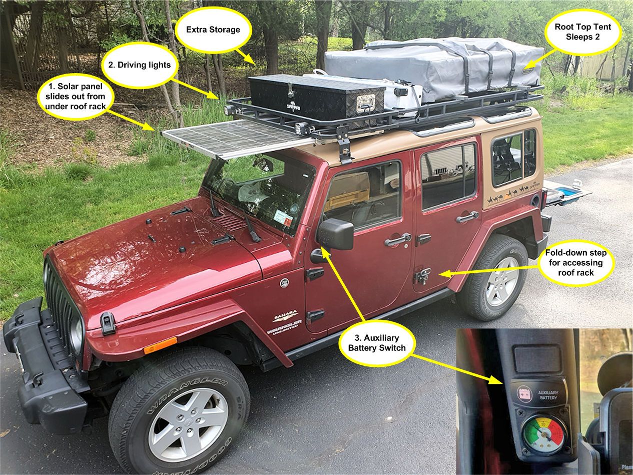
Overland1.jpg


1. The solar panel normally charges the auxiliary battery, but it can be switched to provide charge to both batteries. For driving, it’s stowed under the roof rack and at the campsite it slides out as shown above. It is removable, so if adequate sunlight cannot be achieved with the panel on top of the Jeep, it can be placed on the ground for better aiming.

2. There are Auxbeam driving lights mounted on the rack to improve visibility on dark roads and trails.

3. Auxiliary battery switch. Normally the auxiliary battery is charged by the alternator when the Jeep is running and when the Jeep is not running the auxiliary battery is isolated from the main battery. This switch connects the auxiliary battery to the main battery so the auxiliary battery can be used to start the Jeep and also the solar panel can deliver charge to the main battery.

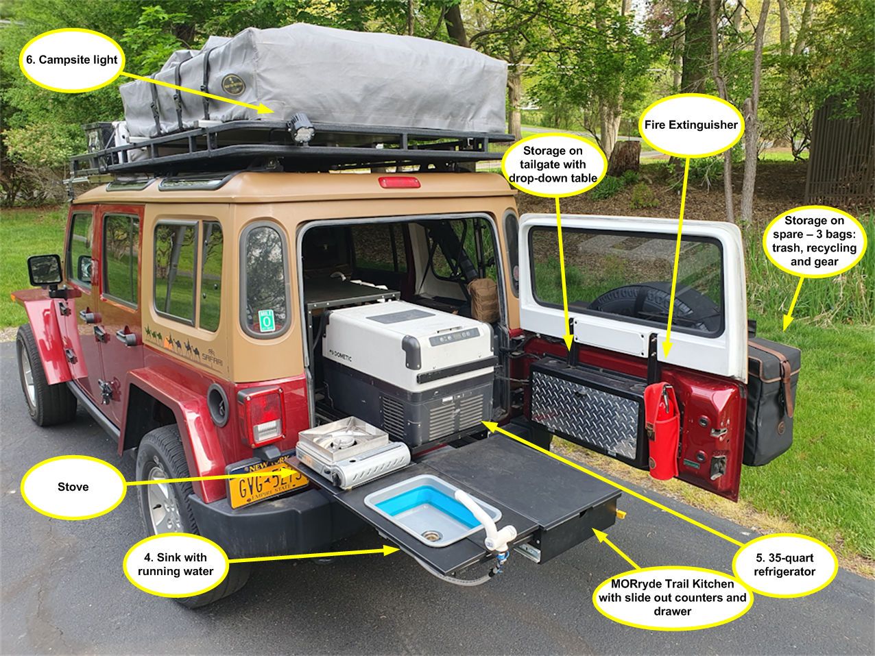
Overland2_kuhefcMVruU3zR3FsxqiJm.jpg


4. The sink has an electrical demand pump (turns on when the faucet is opened).

5. A 35-quart refrigerator has proven adequate for most expeditions we use this Jeep for.

6. An LED light mounted to the roof rack provides light for the campsite. It’s an Auxbeam driving light, which is actually too powerful for this application.

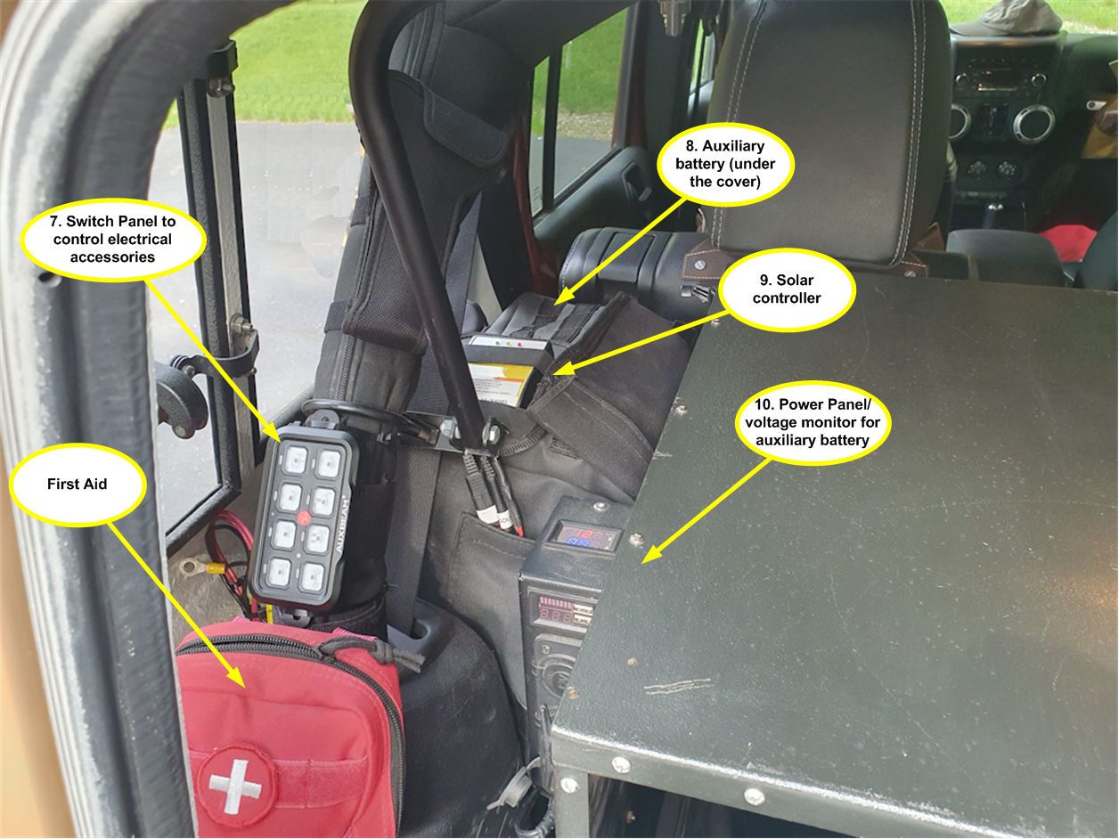
A closer look in the back by the Trail Kitchen:

Overland3.jpg


7. An Auxbeam RA80 X2 switch panel to control electrical accessories. No switch labels have been installed yet, it's still a work in progress.

8. The auxiliary battery is stored over the inner fender on a MORryde battery/ammo can tray. It’s a group 24 deep cycle marine battery from Walmart. I chose that battery because 1) there are Walmarts everywhere so if it fails on the road I can swap it at the nearest Walmart and 2) it's very affordable.

9. The solar controller is a $20 item from Harbor Freight and has proven to work very well.

10. The MORryde Power Panel option for the Trail Kitchen provides battery voltage and current drain monitoring and power outlets and USB outlets.

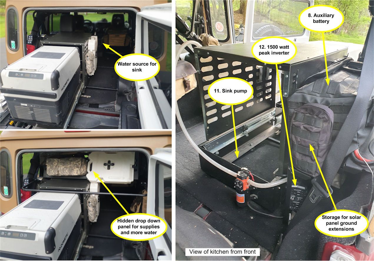
The sink water sources and a view of the Trail Kitchen from the front.

Overland4.jpg


8. Another view of where the auxiliary battery is mounted. It’s got a cover made from soft top fabric with MOLLE grids on it so pouches with electrical accessories such as the ground extension cord for the solar panel can be stored on the cover.

11. The sink pump is part of the MORryde Trail Kitchen Deluxe Sink Option. It’s a demand pump so it only runs when it senses low pressure – when the faucet is opened pressure drops and the pump starts running.

12. A 1500-watt peak (750 watt continuous) power inverter provides power to our portable rice cooker, electric blanket and power tools when necessary.

We don’t take this on every expedition, but when hot showers are needed…

Overland5.jpg


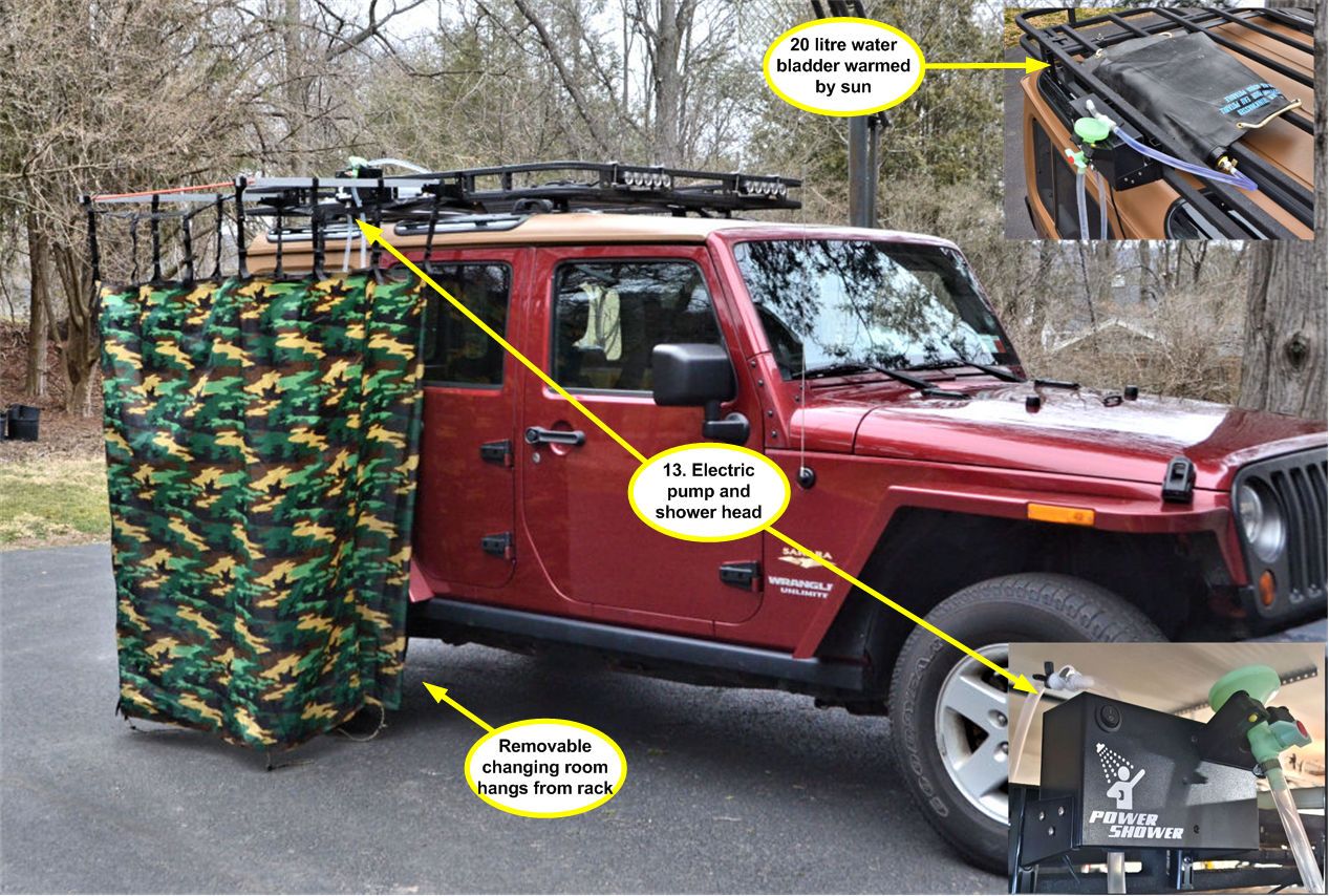
13. The Power Shower has a demand pump to provide water pressure. Heated water is provided by the sun to a 20-liter black Swiss Army surplus water bladder that sits on the roof rack at the campsite. The shower enclosure and the pump attach to the rack with quick release brackets and are stored inside the Jeep when on the road.
 

jscherb

Expedition Leader
Looks like you have everything you need to go camping!
Except some air conditioning for here in Texas.
We'll be driving across Texas tomorrow (Tuesday), we're on our way to Overland West in Flagstaff. We won't have time to test the Texas temperature in the tent though, the tent is on top of the Jeep for this trip but we're on a tight schedule to get to Flagstaff so no camping along the way.

We're a few hours behind schedule due to a mechanical problem. Just east of Indianapolis (600 miles from home) as we were pulling into a gas station, a terrible squeak started. It sounded like a rock might have gotten between a backing plate and a rotor, so I took the rear tires off (noise seemed to be in the back) to inspect but nothing. Driving after the gas stop it was behaving like a bad CV joint in the rear driveshaft, so I pulled over to inspect that and found the front one was hot.

I just replaced both CV joints about 5000 miles ago when one went bad, and one of the replacements failed. Since it was heating up, driving more would have invited catastrophic failure, so driving much further was out of the question. What to do? 600 miles from home and 1500 miles from Flagstaff and a show to get to.

So I removed the rear driveshaft, put it in 4wd and continued on the way in front wheel drive. It's behaving just fine at interstate speeds, so when we cross Texas tomorrow it will be in 2wd on the front axle. It was either that or turn around and go home so I decided to push on.

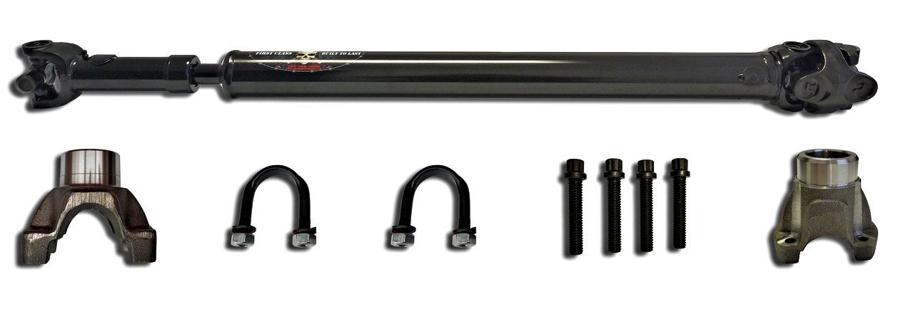
I think maybe after two CV joint failures it's time to do something with real u-joints like this: https://www.adamsdriveshaftoffroad....veshaft-greasable-u-joints-heavy-duty-series/

Took this photo before the failure at a Culvers where we stopped for lunch.

OhioCulvers.jpg
 

14JKURX

Observer
Welcome to TEXAS even if it was just a pass through.
Hopefully you were able to complete your journey without any further problems.
 

jscherb

Expedition Leader
I ordered a new rear driveshaft from Adams today. It's a u-joint shaft rather than the factory CV shaft. It comes with new yokes to accept the u-joints. This will be much easier to service if there's ever an issue on the road. This image is from the Adams web site:

AdamDriveshaft.jpg


We arrived in Flagstaff yesterday; it's 1600 miles from Indianapolis where the CV joint failed so we did 1600 miles in front wheel drive with the bad driveshaft up on the roof rack. It'll be about 24 miles back home and we'll do that in front wheel drive too. The jeep drives surprisingly well with the rear driveshaft out, the only time you notice any difference is on hard acceleration from a stop some torque steer can be felt, similar to many front wheel drive vehicles. Even so, I'd rather not drive all this way on only the front axle, but it seems to be the choice that sucks the least at the moment.

Adams says they'll build and ship the driveshaft tomorrow, so I should have it by the middle of next week.

Today was setup day at Overland West. I'll post photos over the next few days as I wander the show.
 
Thank you for the kind words. Yes, I'm well acquainted with Sailrite, my main sewing machine is a Sailrite Ultrafeed LSZ-1 with the servo motor and Monster II balance wheel options - with those options I can sew very thick layers of heavy fabric at extremely slow speeds. It has no trouble with multiple layers of factory soft top fabric including sewing through plastic stiffeners or multiple layers of leather. It's my second favorite power tool :).

UltraFeedLSZ-1.jpg
BINGO! Fifty years ago I worked as a production stitcher for Ted Hood. They had one customized Singer machine where the bottom stitch mechanics ran down under the floor and back up in a "U" thus clearing the center space for hauling large sails through.
 

Forum statistics

Threads
188,194
Messages
2,903,698
Members
229,665
Latest member
SANelson
Top