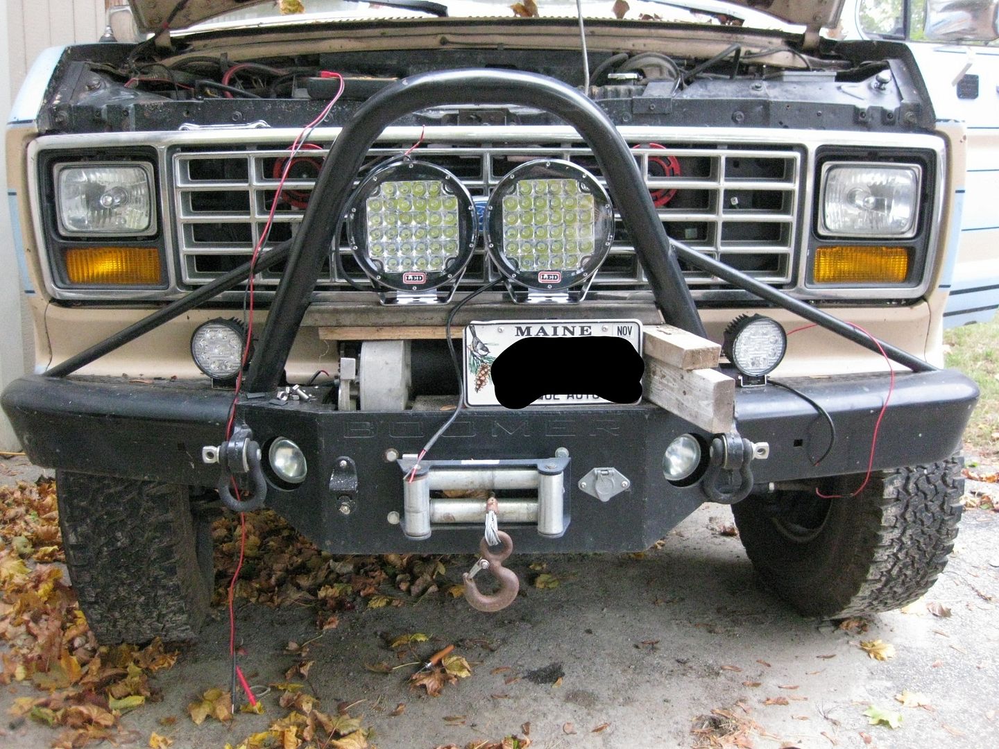
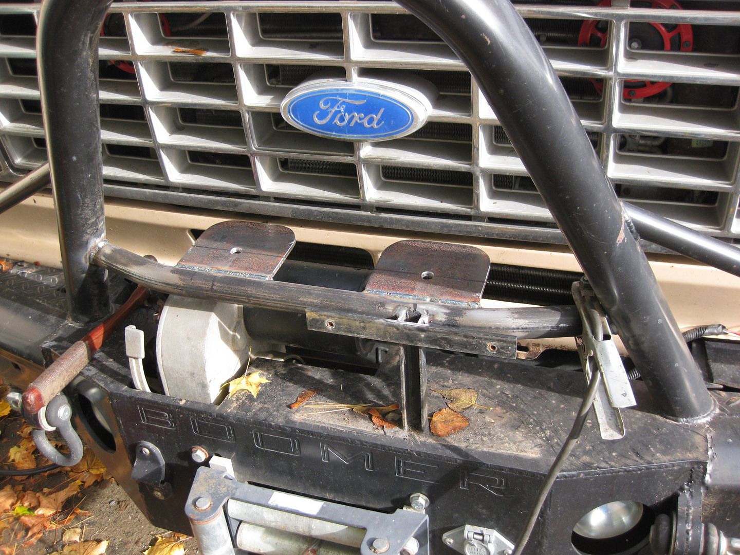
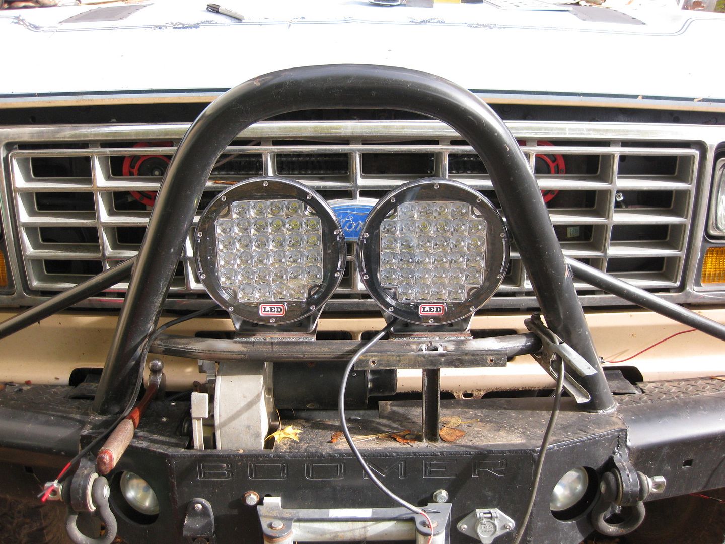
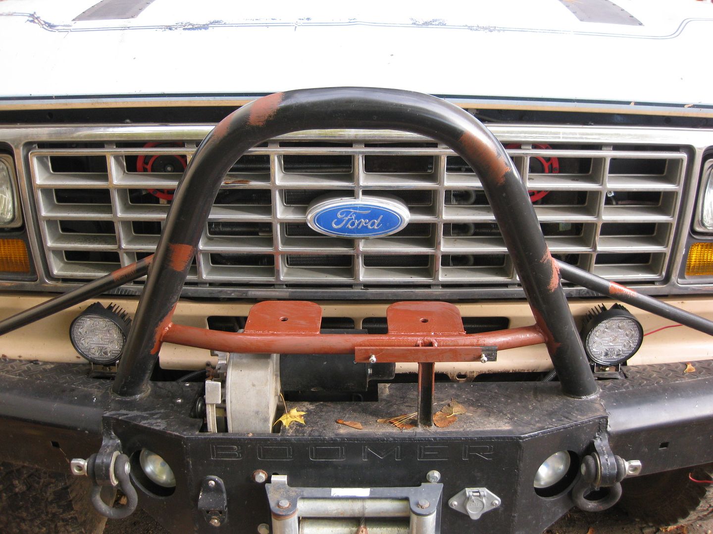
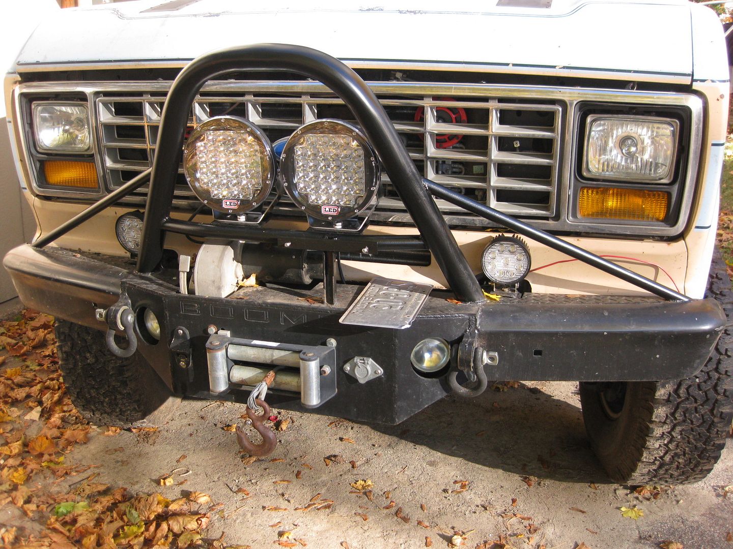
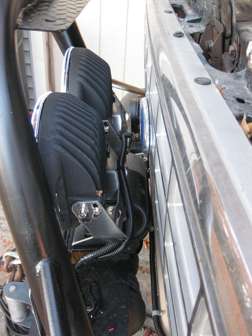
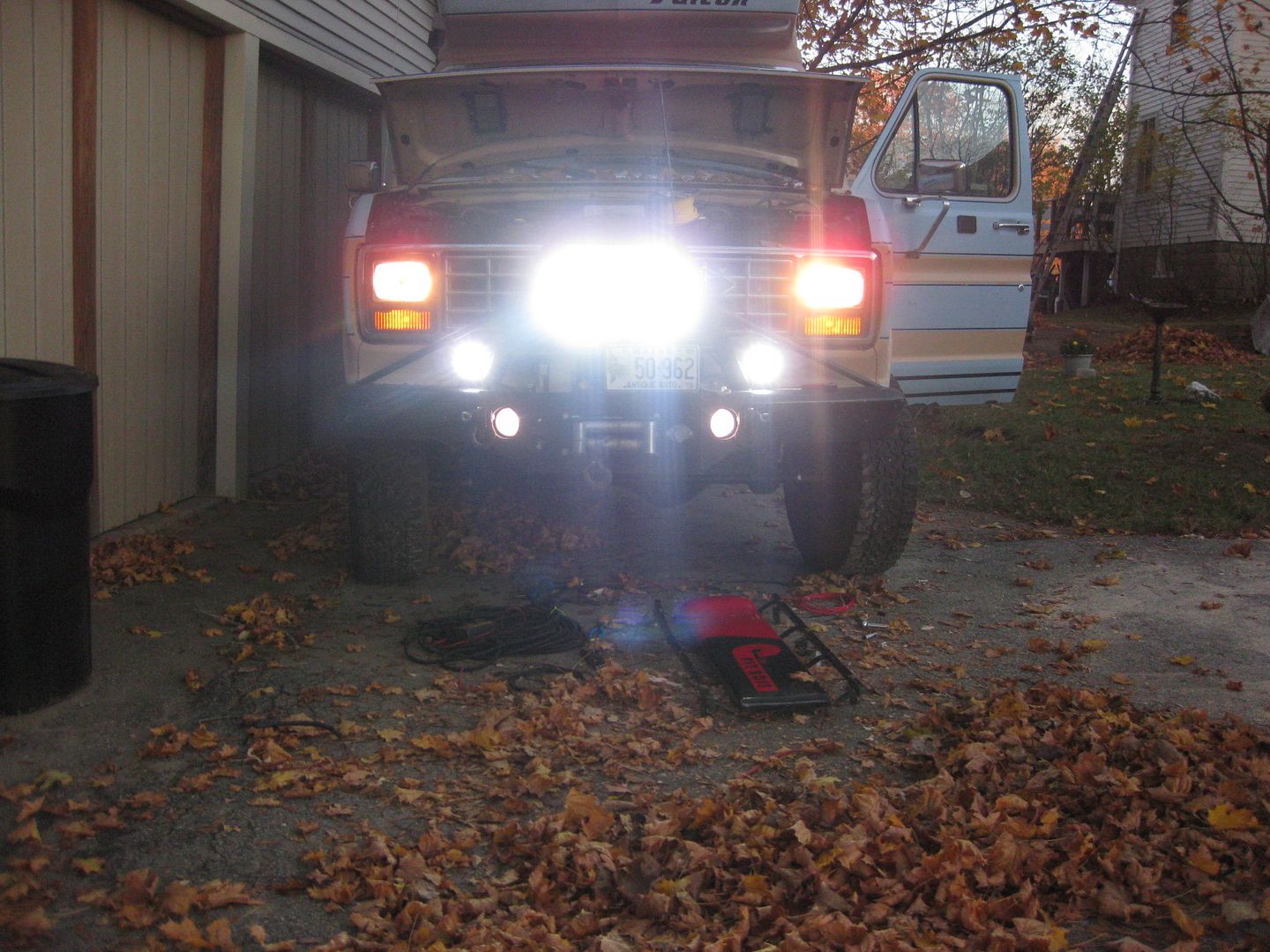
Thanks...those silly bumpers continue to be one of the most popular bits on the rig. Whoodathunk?
So...3G Alternator Install for Dummies.
First things first,
READ THIS THREAD. Then
READ IT AGAIN.
For the most part, all the information in the Ford-Trucks thread is good and applicable. I wouldn't have attempted this modification without some step-by-step information from other sources. For whatever reason, the core functioning requirements of an alternator (from a wiring perspective) has been something I'd had a hard time grasping for years. You've got your field wiring, exciter circuits, yada yada. It isn't complicated stuff, but I just haven't ever intuitively captured it in my "forever" knowledge bank.
So as we start talking about alternators my eyes glaze over quickly. The 1G alternator is an externally regulated unit dating back to the mid 60's, and used in Ford production thru 1986. Boomer had to have one of the last production models, as most Ford cars and trucks by 1986 had been converted over to 2G alternators (internally regulated) starting in 1982. The specs on my particular unit aren't important except to say that it was a 60A (yes...60) model capable of only 25A of output below 1000 engine RPM. It has been time for an upgrade for a long long time.
One of the first critical items to emphasize is that if you have an old vehicle with a small electrical system (i.e. 60A), it is probably not a good idea to just throw a larger alternator under the hood. With small alternators comes small wiring, and dumping large current thru small wires = fire. In the case of Boomer, I have already been thru all of the load carrying wire throughout the rig, with my starter bank wired with 4-0, and my house bank wired with #2 thru mega fuses at each end. All relays and other load-critical components have been sized all along for a 200A continuous load.
The first thing you should have is your maintenance manual and open to the wiring diagrams.
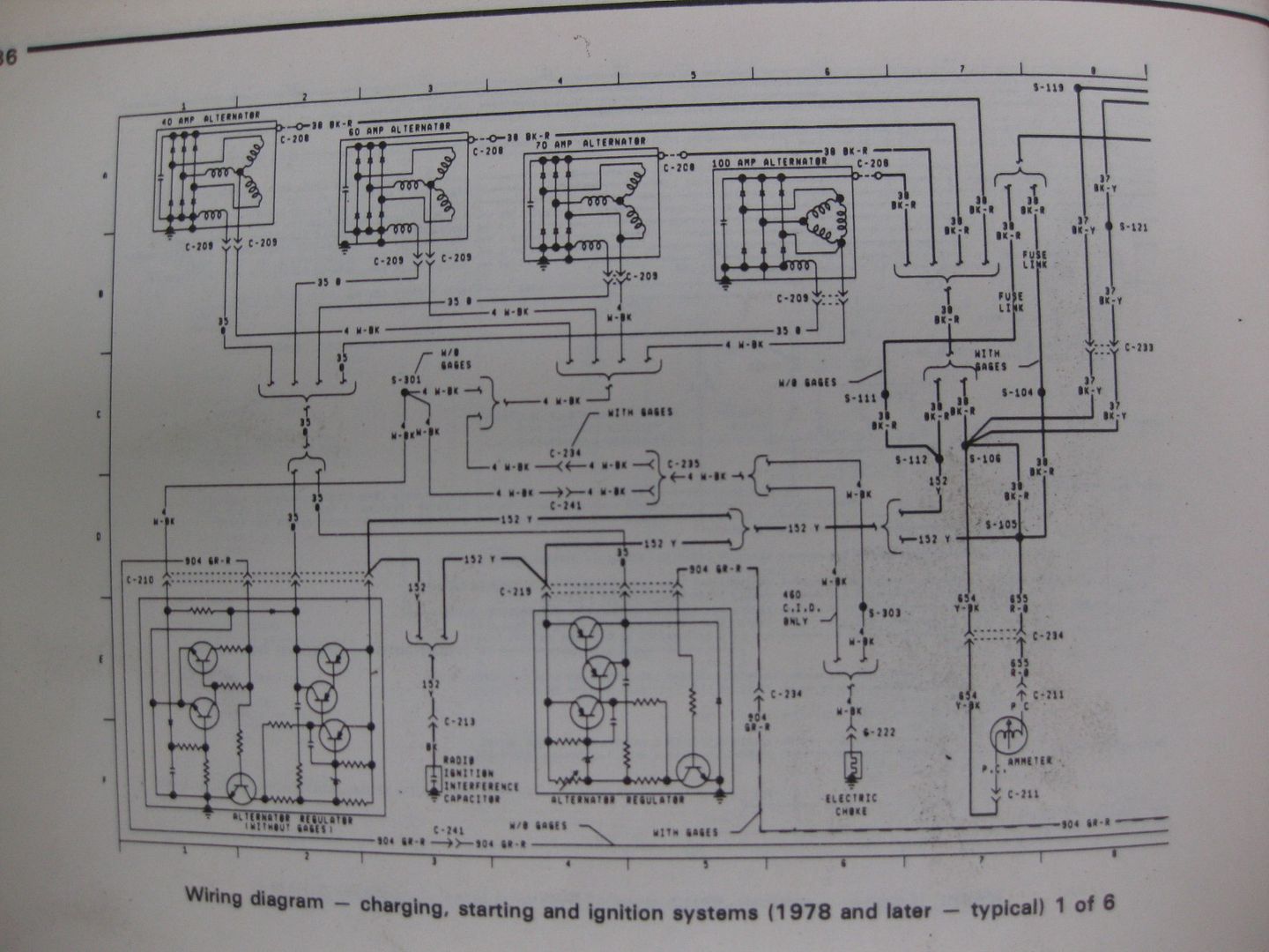
At first this is terribly confusing, but as you start digging into the looms it will all start becoming clear.
In my case, the first step under the hood was the removal of the upper radiator hose so I could liberate the old alternator. Remove the negative battery cables so as to ensure you won't zap something while mucking around under the hood.
I had already acquired a new 3G alternator from a 1995 Ford Windstar w/ 3.8L V6. This is a large case unit which bolts right in place of the stock alternator.
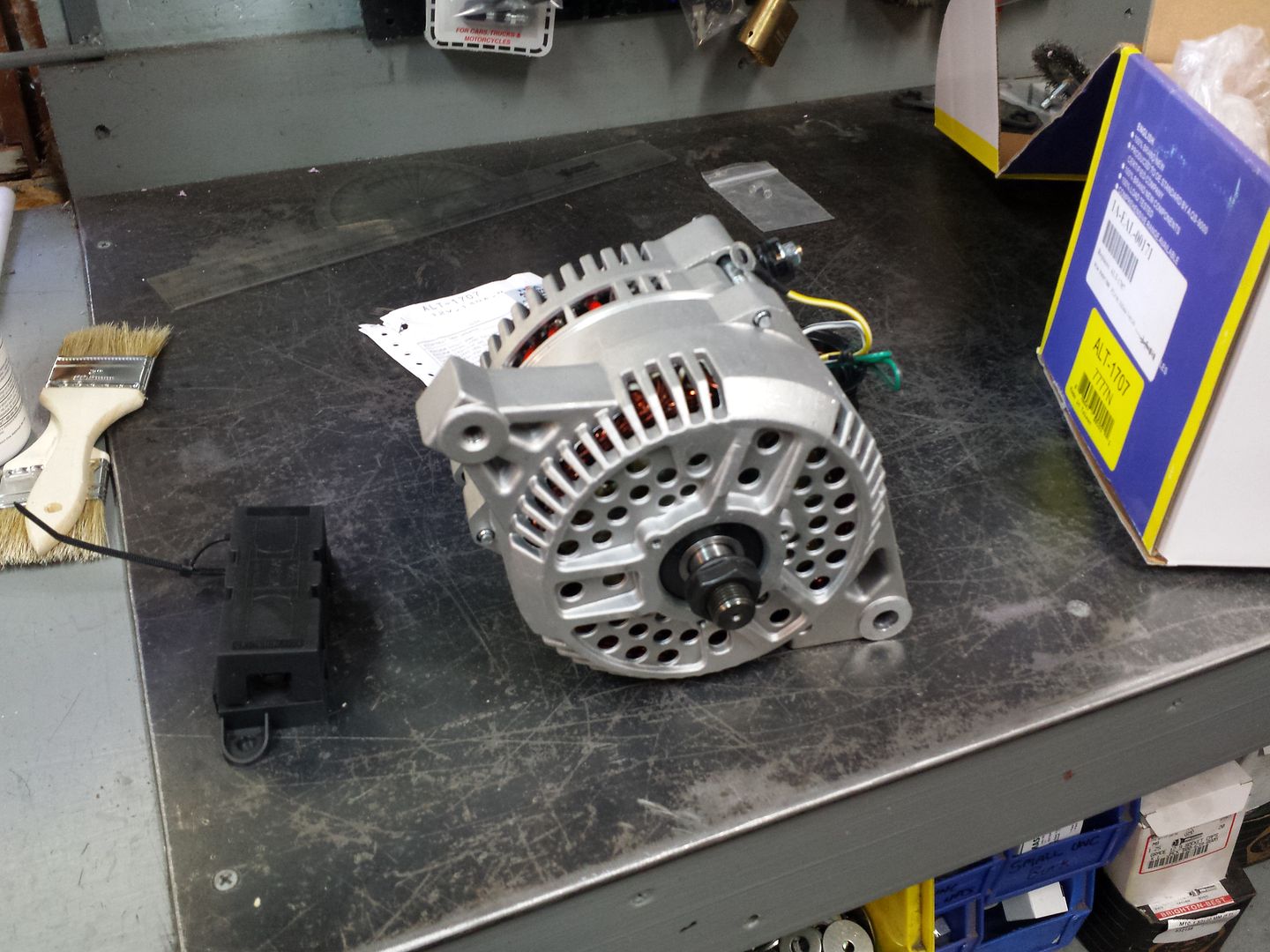
The only thing to be taken from the old alternator is the drive pulley. You'll want an impact gun of some sort.
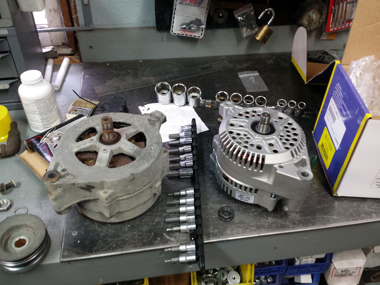
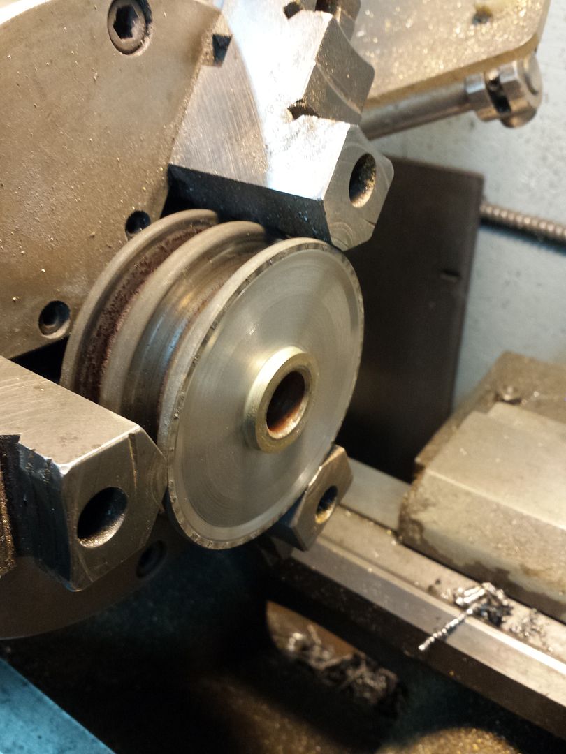
You'll notice the old one on the left has a spacer at the base of the shaft, while the one on the right does not. The spacer will not be relocated to the new alternator as it will throw off the pulley alignment relative to the case. Unfortunately it isn't as easy as just bolting on the pulley, as there is a very slight (less than 0.020" clearance issue. Some people take the small washer which is used on the old alternator between the pulley and nut, and use that as a spacer on the new one between the pulley and the bearing. The spacer is around 0.075" which seemed excessive, so I threw my pulley in the lathe and turned some clearance on the back side. Most people don't have access to equipment like this so probably that 0.075" spacer would be fine. Note that the stock fan does not transfer to the new alternator, as the 3G has an internal fan.
With that sorted and the pulley secured to the 3G unit, I reclocked the case 120 degrees to align the battery and connection posts to the top. This simply requires removing the 3 perimeter bolts and spinning everything 120 degrees. Be careful re-tightening as there isn't a positive flange which forces everything back into a concentric alignment....you'll need to "tweak" the bolt tightness to ensure there isn't any binding and that the rotor spins freely.
Now its time for some fun with wiring.
You should have already removed your negative battery cables...if not, do it now.
I would have benefited from removing my passenger side starter battery (hindsight, 20/20), so if you can do that it would be much better. All the wiring you'll be accessing runs along the passenger fender liner and along the far outside near the battery tray.
There is a loom which can be fully removed, starting at the alternator and going forward under the battery tray and just over the passenger headlight. There will be 2 disconnect plugs and a yellow thick wire (~8 ga) which is bolted to the starter solenoid just above the back of the PS headlight. You'll find the alternator external regulator right next to the starter solenoid, so remove that and take the whole loom out.
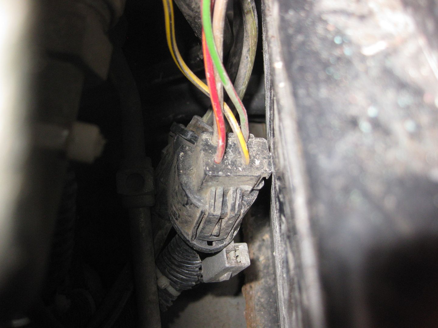
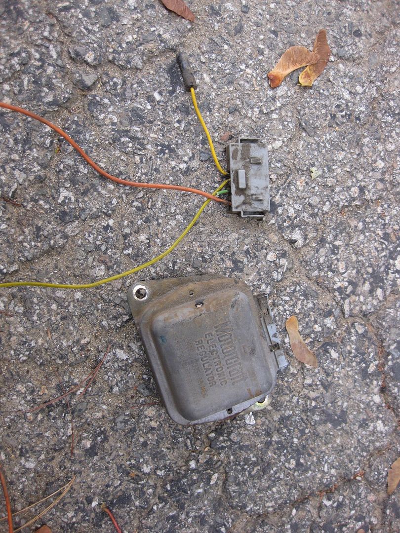
When you pull the wires out of the loom you'll find a couple funky factory splices. Cut the black wire that goes to the old alternator "BAT" stud off at this particular junction, then seal back up with heat shrink tubing.

At the other junction in the loom, you'll cut back the yellow wire coming from the external regulator. Re-seal this junction up with heat shrink and electrical tape as well.
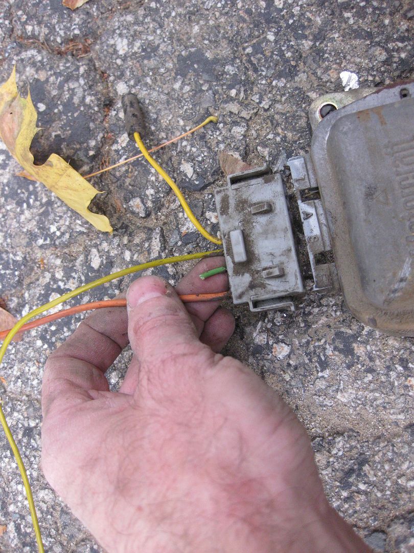
The Green and Red wire coming out of the "S" tab on the external regulator is the only wire associated with the old alternator that you'll use.
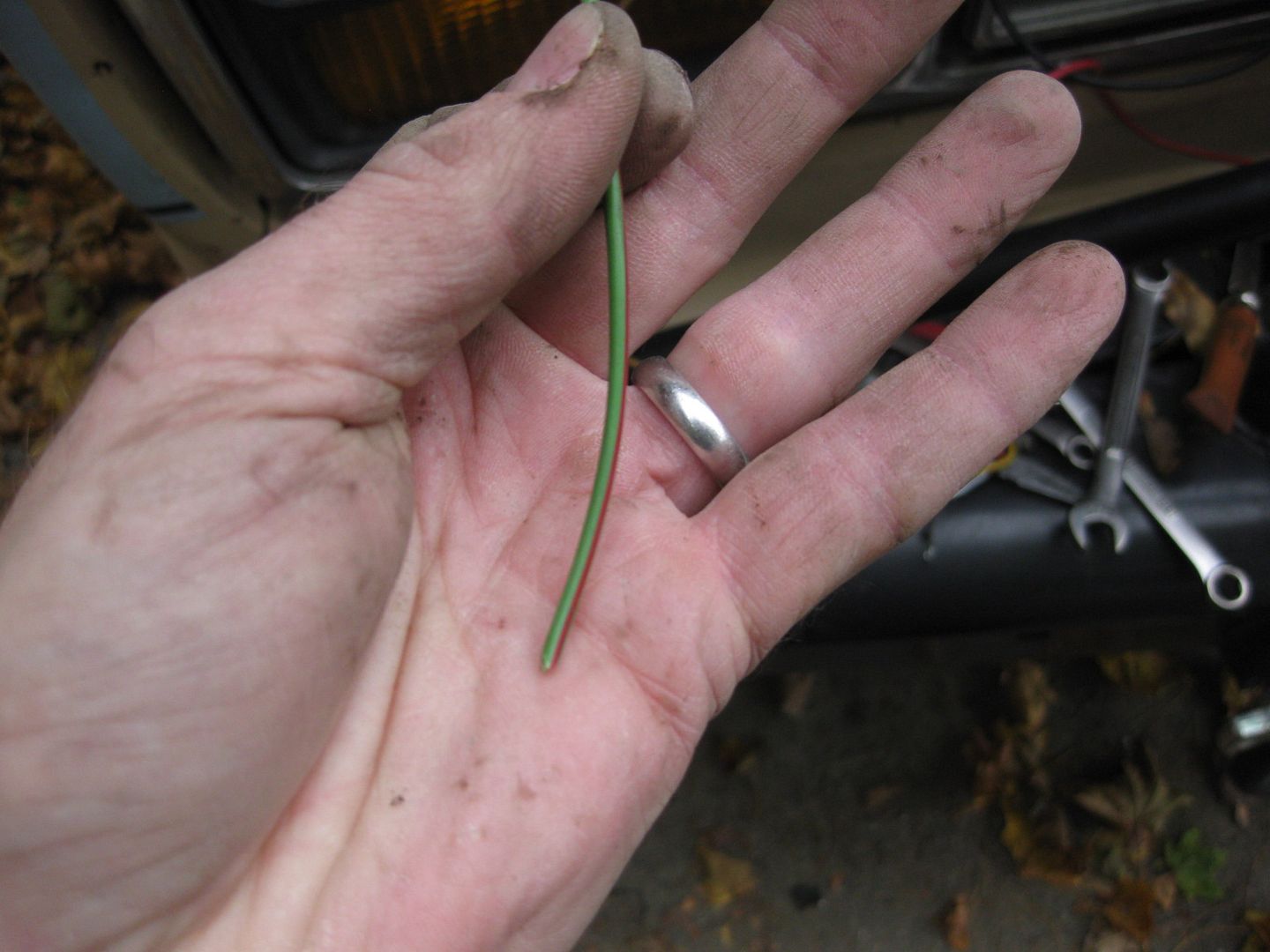
Here you can see the position that the green and red wire is cut from on the regulator plug. The yellow wire from the regulator (which you clipped back at the junction, as well as the (orange??) wire which is also clipped back to the plug can be seen here.
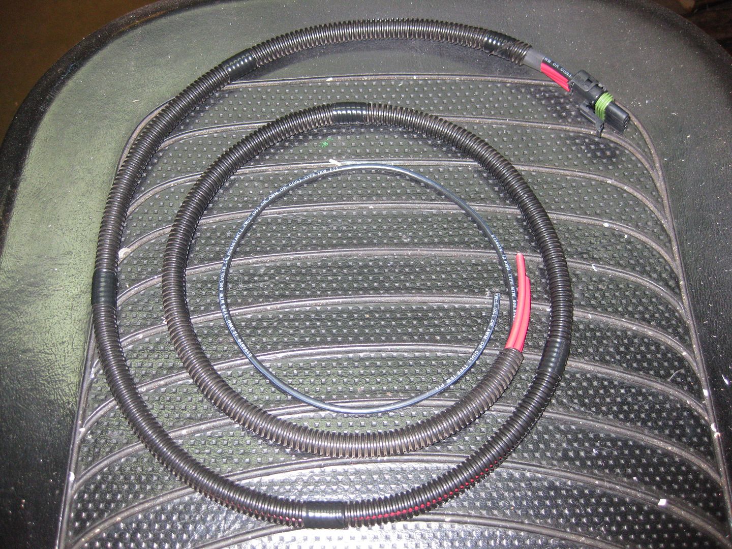
Solder a 3 foot piece of green (or better yet, green and red) wire to the clipped off section of green and red wire from the loom, and re-cover with the plastic split sleeve in preperation for re-assembly. You should have a nice looking loom at this point.
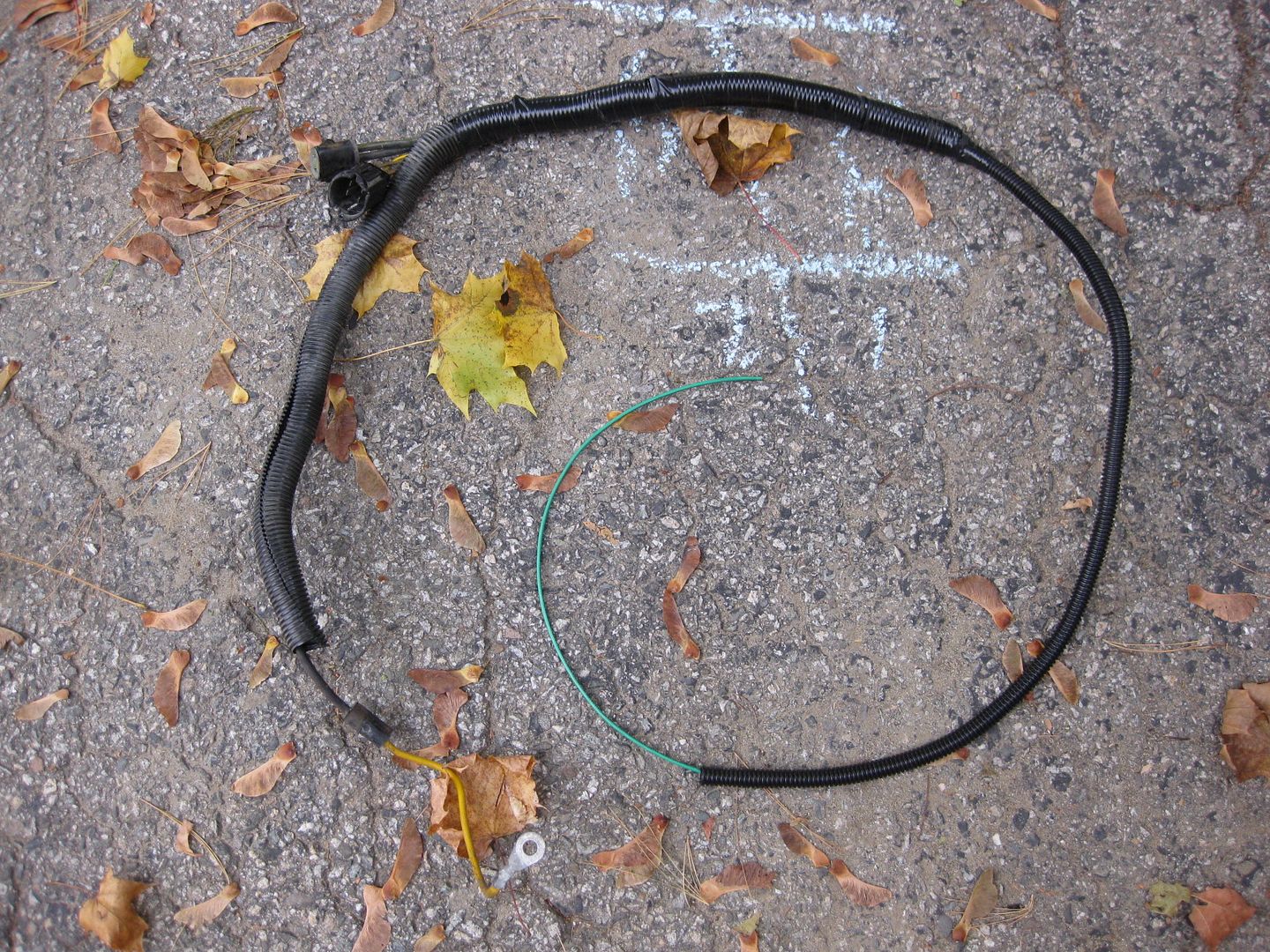
The yellow wire will not be reconnected to the starter solenoid. Lube up the connectors with dielectric grease before plugging everything back in. Dry-assemble the loom in place and snip the green/red wire to the correct length to mate with the alternator.
You'll be wiring your alternator plug set to the green wire now. You can either do this in-place, or remove the loom once more.
The connector set you'll need either comes from the junkyard from a vehicle that had the 3G alternator stock, or from ebay.
I did the
ebay thing.
The green/stripe (stripe color on my connector was black) gets soldered and heat-shrunk to the green/red wire in your remanufactured loom.
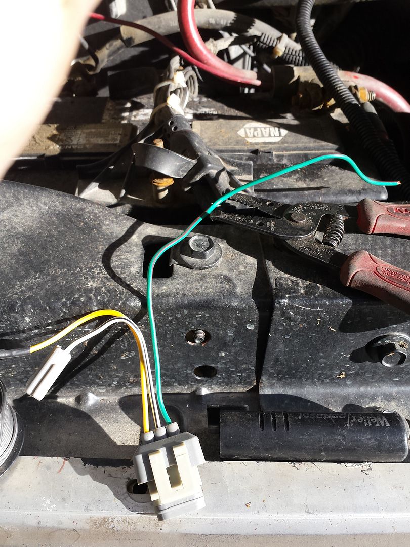
At this point you can re-install your loom, making sure all your chafe protection is in place and you've liberally zip-tied everything away from hot and spinny bits.
You can plug the large plug into the alternator, the small plug into the alternator, and mate the ring terminal/yellow wire from the large plug to the battery post on the alternator.
Now it is time to get your
mega fuse holder and 175A mega fuse ( you got that already, right) and mount them somewhere convenient. I found the best place in my installation was on the passenger side battery hold-down.
Yes, bad picture but you get the idea.
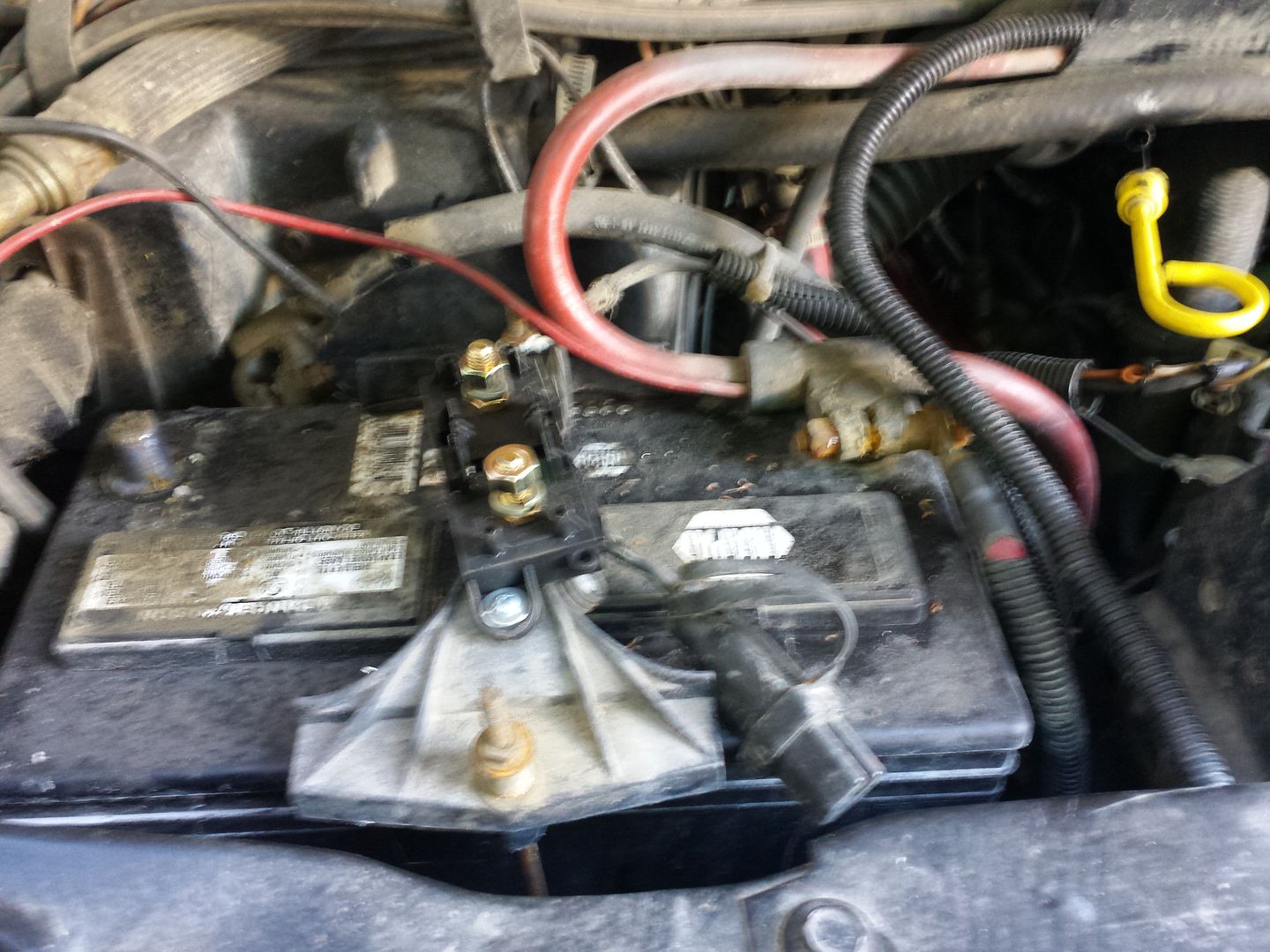
Once this is securely mounted, you'll need about 3 feet of #4 fine strand battery cable, 3 solder-on 5/16" terminals and 1 solder-on 1/4" terminal. You'll be making a connection between the alternator (the only 1/4" terminal) and one side of the fuse holder, and another connection between the other side of the fuse holder and your positive battery post. Solder and heat shrink. My battery post already had bolt studs for my front winch so this was an easy connection. You may need to add a longer bolt to the battery clamp to allow adding a power connection here. It must be robust no matter what your solution.
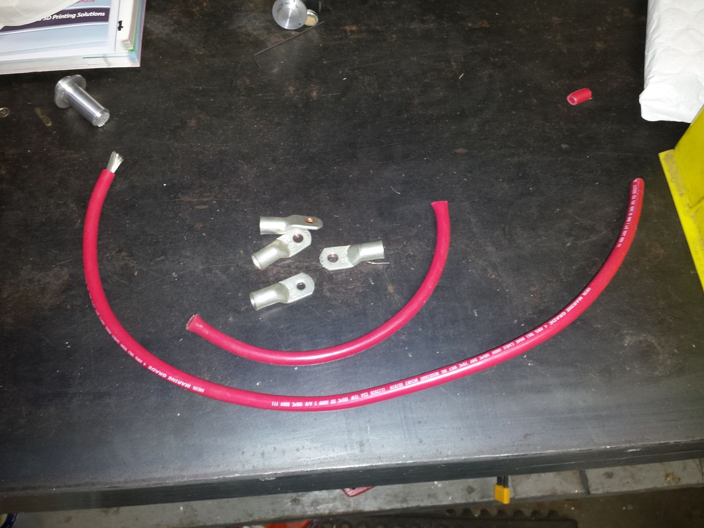
Make your final connections. The yellow large gauge wire from your loom will connect to the fuse block. Reconnect your battery terminals, make sure your tools are all put away and the alternator belts (and in my case, the vacuum pump belts as well), and let 'er rip. You should see 14.1-14.4V at the batteries once the engine is running. If not, check your connections and ensure you've got the correct wires all hooked up...and you've got your fuse in place!
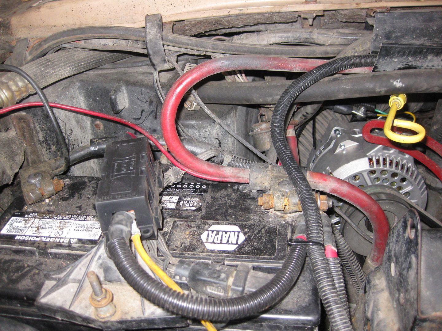
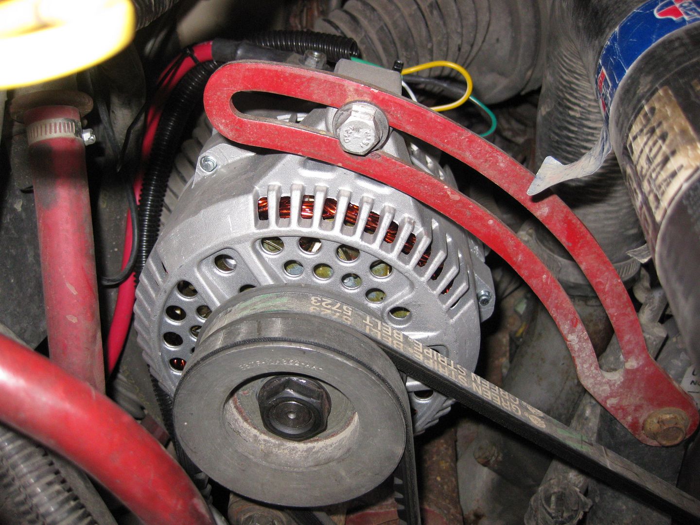
There. Easy as that. Now I've got 100A at idle and 150A at cruise. Much better.
SG


