Charging 12v LiFePo4 battery bank from 24v alternator - Isuzu NPS

Stafford

Member
Whats the best wAy to charge a 12v LiFePo4 battery bank from my isuzu NPS 24v alternator?

Battery manufacturer says that they are best charged with 14.2v, but 14.4 is ok too, and are dead at 11.5v.

I will have a separate MPPT solar reg attached feeding it a max of 30A.

My concern is that products designed for lead acid will think the battery is half full at 11.5 volts and not deliver maximum charging amps from the alternator...

Could i just use another MPPT solar controller? Or a DC-DC charger is better?

Oh yes, the Redarc BCDC line is too expensive given that i already have a separate solar charging system.
 

SkiFreak

Crazy Person
Argh... to have a 24V truck.
If I were in your situation I would definitely use a programmable solar regulator. I do not think that I would use a MPPT regulator, as the benefits of that technology would be lost when using a constant power source, like an alternator. I believe that a PWM regulator would be cheaper and would do the job just as well, if not better.

When charging LiFePO4 batteries from an alternator there are two things you need to control.
1. The voltage going to the batteries.
2. The current draw on the alternator.

A solar regulator requires a voltage differential between the input and output voltages in order to work. With a 24V alternator (which will probably output over 28V) this is not an issue if you plan on charging a nominal 12V battery bank and it should work well. Having a regulator that is programmable will allow you to set an optimal charging voltage for the batteries. You did not mention what brand of LiFePO4 batteries you are using, so I will not guess and suggest an ideal voltage for your setup. What I will say at this time is that you should not believe everything that you read about the best charging voltage of LiFePO4 batteries.

Every lithium charger that I have looked at has too high a charging voltage in my opinion and they all still "float" LiFePO4 batteries, which is not ideal.
Take a mobile phone that uses lithium batteries as an example (yes, I know they are are a different chemistry, but the charging logic is the similar). When the battery is full the charger turns off. No one has been able to explain to me why this does not happen in the RV LiFePO4 battery charging market.
I strongly believe that the float voltage should be set to a value below the resting voltage of the LiFePO4 batteries, effectively turning the charger off after the absorption phase.

When a LiFePO4 battery bank is at a low state of charge it will take whatever power it can get out of a charge source. For this reason there needs to be some current limiting built into the charger, or you will likely run your alternator at 100% capacity and seriously reduce it lifespan. I would suggest limiting the charger to a maximum of 60% of the alternator capacity, but lower would be better. Remember, you will likely be driving for some time, so even with a lower charge output the batteries should still get fully charged.

I have 400A of Winston LiFePO4 batteries and charge them at 13.9v and float them at 13.2v.
 

SkiFreak

Crazy Person
Another alternative is to simply use one MPPT regulator that can handle both your PV and alternator outputs. The only thing you would need to be careful of here is that the voltage output of your PV array was close to that of your alternator.
If you had a 100A alternator and used a 60A MPPT regulator it could utilize the PV and alternator outputs and negate any charging issues with using multiple regulators.
On a rainy/cloudy day, or at night, the alternator would provide the majority of the charging and on a sunny day there would be less load on the alternator, as the PV output would be combined with the alternator output, to the maximum of 60A.
 

gait

Explorer
...My concern is that products designed for lead acid will think the battery is half full at 11.5 volts and not deliver maximum charging amps from the alternator...

no need to be concerned. The alternator (or any other charger) will deliver everything it can until the charging voltage reaches the absorption set point (14.2 or whatever its set to).

...
Every lithium charger that I have looked at has too high a charging voltage in my opinion and they all still "float" LiFePO4 batteries, which is not ideal.
Take a mobile phone that uses lithium batteries as an example (yes, I know they are are a different chemistry, but the charging logic is the similar). When the battery is full the charger turns off. No one has been able to explain to me why this does not happen in the RV LiFePO4 battery charging market.

The duty cycle is different.

A mobile phone gets charged, takes very little current sitting idle, is disconnected from charger when used (its what mobile is for), returned to charger when user gets beeped at or thinks its time.Plugging in the charger is the "start charging" event.

An RV charges then someone turns an appliance on which may drain a lot or a little. The charger then needs to start charging again. Most RV suitable chargers (all solar?) simply sense volts and revert to "boost" when the volts drop below "float" volts for some seconds. A different "start charging" event.

Whether to float LYP seems to revolve around the (perceived?) reduction in life when keeping it fully charged.
 
Last edited:

Stafford

Member
Thanks Skifreak and Gait, thats great information.

I think I should keep the alternator and solar regulators separate to build in some redundancy. That way hopefully Ill never be stuck :)

If I was to use a 30A regulator for the alternator, could the alternator potentially supply more current to the regulator and blow it? Or are regulators generally current limited? As you said Skifreak "there needs to be some current limiting built into the charger".

So yeah, does a 30A PWM regulator mean that it is current limited in its current draw too?

Like the one in this link:
http://www.victronenergy.com/upload/documents/Datasheet-BlueSolar-PWM-Pro-Charge-Controllers-EN.pdf
 

Haf-E

Expedition Leader
Do not use a PWM type solar controller with an alternator - it will not work AND it will either damage the alternator or the controller. I've seen them fail a couple of times. The fast on-off of the PWM controller causes the voltage of the alternator to spike up to hundreds of volts. Its similar to what happens if you disconnect a running alternator from a battery - the current flowing "flys back" becoming very high voltage. Boom.

I do not know of any PWM controllers which are able to limit the current in the way a MPPT controller can - but even then, there are limits to what even a MPPT type controller can do. I would check with the manufacturer first before trying anything. Limiting the current from a solar panel is relatively easy (they are a current and voltage limited source) - doing it from an engine driven alternator is much more difficult (due to the stored energy in the windings).

I have used a MPPT controller to charge a 12vdc battery from a 24vdc battery - Which might be the best option for your system. The only challenge is that I don't know of any which are setup to only do it when the 24vdc battery is being charged from the solar or the alternator. I added an additional relay on mine which only connected the MPPT controller when the engine was running and had the solar charge the 12vdc battery directly. I don't know if all of the MPPT controllers can do this - the one I used was an Outback FlexMax 60 which are not cheap unfortunately ($500 USD?). The advantage is that it has a programmable current limit for the output so it can be adjusted to match the size of the battery.

I think the typical RV or Solar chargers float the battery because there are typically DC loads connected to the battery all of the time which draw current - which is different from a laptop or cell phone when it is plugged in. I agree with using a lower float voltage setting to reduce float charging.


Having one MPPT controller do both the solar and the 24vdc to 12 vdc charging is possible - it would require some diodes and/or relays to work I think - but as you mentioned, you don't have an redundancy or fault tolerance then. I would use two separate but identical MPPT controllers to allow swapping if a problem occurred.

The Victron controller you linked to appears to be a positive ground (i.e. common positive in/out) so I would be very weary of using that in a vehicle application. It wouldn't work with an alternator anyways.
 

LeishaShannon

Adventurer
Any reason you're not sticking with 24v for the house bank? quicker charging, more efficient, less cable weight, etc etc. One of the main benefits of Lithium is the high charge acceptance, seems silly to hamstring it to 30A ( ~400W) or whatever when a direct connection and a simple relay will allow charging at 3000W+

Whatever solution you find make sure its programmable, rather than one with a "lithium setting" as the setting will most likely be wrong for your specific batteries and usage pattern.
 

Haf-E

Expedition Leader
Not all Lithium batteries have high charging acceptance. I agree about the full adjustability of the charge controller. Some type of battery monitor (amp-hour counting in / out, voltage readings min/max, etc.) is also very valuable.
 

yabanja

Explorer
I have abandoned my plan to use LifePO4 batteries. I have concerns about their sensitivity to heat and cold.

Allan
 

gait

Explorer
some solar regulators emit smoke when over supplied, others are limited. Need to read the specs carefully.

MPPT is basically a relatively high frequency pwm driven transistor and a coil. A variation of buck mode voltage reduction. Simplistically, once absorption volts is reached MPPT is irrelevant and output voltage is pwm controlled.

If it were me I'd experiment with a solid state relay, voltage measurement, current measurement, and an Arduino to control. From 24v battery connected to alternator to 12v battery. Alternatively DC-DC charger.
 

Haf-E

Expedition Leader
MPPT controllers are actually DC-DC converters - the good ones produce nearly ripple free output current which is what a battery wants when recharging. They use a combination of transistors, inductors (coils) and capacitors - and are nearly all controlled by a microprocessor. Some allow setting of a current limit (which is critical when connecting a battery as the source instead of a PV array) while others don't.

Using a solid state relay to charge a 12vdc battery from a 24vdc battery would result in very high current pulses - and possibly would fry the SS relay or at least make it really hot. Even if it survived the 12vdc battery would not charge well and you probably would be way outside of the recommended charging rate. The high ripple 24vdc voltage might also result in problems with other vehicle components - especially if it has any CANbus communications.

I would just go with a proven off-the-shelf solution myself.
 

gait

Explorer
for 24v->12v DC-DC converter = buck mode?

The battery being charged provides smoothing for SSR driven from an Arduino PWM pin at 500hz. Reason I said experiment is I've only used the approach for 12v to 3.5v for initial parallel balancing charge of LYP. A bit different, it also works for solar to battery where the voltage drop due to SSR resistance increases the panel volts rather than reducing panel current - just shifts the loss from not operating at MPP. I first read of that approach in a Plasmatronics (Aus manufacturer of PWM solar regulator) publication suggesting how to expand the panel capacity of their PWM regulators. The current sensor I mentioned is used by the Arduino to limit current if voltage set point is not reached. It also stops overloading the SSR. Conventional constant current - constant voltage charging.

FWIW I'm part way through implementation of Arduino based integrated solar -> LYP regulator, battery management at cell level, soc meter, with appropriate alarms and cutouts. 12v vehicle and 12v house so don't have the problem with 24v vehicle -> 12v house that OP raised.
 

Stafford

Member
Thanks for all the replies, as solar is so cheap im getting 750w of panels and will keep the house system separate from the alternator for now. Clearly need to do some testing! Gait that arduino system sounds very interesting, i have just gotten into making some Arduino devices and have been wondering how they could help with my housetruck.
 

gait

Explorer
I got frustrated with off the shelf battery charging stuff a long time ago. LYP batteries meant I really needed to put money where mouth is.

I'm part way through build and document, while also rebuilding truck (long story), plus a bit crook.

Battery management is a single chip that measures cell volts and provides for balancing plus a couple of alarms. This is the one I first found, there's a couple of others. http://cds.linear.com/docs/en/datasheet/68022fa.pdf

The Arduino reads the registers on the chip for volts, and a hall effect current sensor for current. Decides if balancing is required. Uses the PID library to output PWM to Solid State Relay. Tuning the PID is a mixture of minimising over run and getting response good. Future is MPPT using Arduino.

I also count amp hours and watt hours for battery SOC.

Restart of charge when full and appliance turned on "should" be sufficient from voltage sensing but I'll tune it with the extra info of current and SOC.

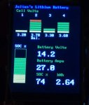
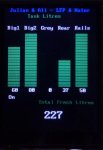
I got a bit ambitious and have a second Arduino for water tanks and a third for display and communications. There's a nice touch screen from 4G.

Where I'm up to is battery charging successful with single volt measurement (without BMS chip). BMS chip reading registers. Touch screen display framework. Now working on multiple master slave RS485 communications between Arduinos. For some silly reason found myself creating own protocol. There are some tricks with data compression so that communications only occurs when something changes, which predicates multiple master slave rather than polling from a single master many slaves. I've checked I can fit all the software on the Arduinos. I also have a big motorised battery isolator, just in case!

Just a case of finding the time. We are due in Canberra at end of October so expect to have version 1 working. Version 2 I'll add web configuration through wifi (harder than extracting data to web page).

Here's a couple of holiday snaps - not real data, yet.

J 036 small.jpg

J 039 small.jpg
 

LeishaShannon

Adventurer
In my (limited) experience balancing is just not required for typical house bank use. Our 18 month old cells are within 10mv of each other at 100% and 20% SoC, even after a few trips down to 0% when doing capacity checks. We've been travelling full time in the truck since May and the LYP cells have performed flawlessly.

Here's a link to a fusion table I created showing a full charge/discharge cycle at 1C https://www.google.com/fusiontables...co_hasLabelsColumn=true&width=1000&height=700

This is a small pack we use for our bikes , and its unlikely you'll ever charge at 1C in typical truck use but it clearly shows no divergence until after 3.45v , and if you zoom in to the end of the discharge you'll see no divergence until 3.1vpc which is practically empty @ 1C discharge rate. (this pack has not even had an initial balance)

I've done tests where i've purposely shorted (via a long extension cord for high resistance) and overcharged individual cells in our 8 cell (24v nominal) house battery and the BMV midpoint has alarmed just as quickly as the individual cell monitoring.

They've only been in use 18 months and only given a real work out more recently (average daily discharge is 185Ah or so this year) but balancing after the initial balance seems unwarranted so far.

It'll be interesting to see how balanced they are in another few years but I'm not expecting any major change from what I've seen so far.

For a 12v system I'd just use a Victron BMV-702 with midpoint monitoring and setup an alarm when cells 1-2 and more than 2% out compared to cells 3-4 and a relay could be fired to disconnect the battery if they get more than 5% out.
 

Forum statistics

Threads
188,604
Messages
2,907,765
Members
230,759
Latest member
Tdavis8695
Top