DIY Lithium Packs, Proposal and Discussion

luthj

Engineer In Residence
The RBS does take a normal switch input, which is what I have (it even comes with a switch).

Instead of dicking around with disconnecting your solar panels, etc, I would just get a 5AH AGM battery (common for UPS, fire alarm systems etc), and wire it in parallel with your lithium bank, on the load side of the BMS. This battery will buffer any voltage spikes when the BMS drops out. It will consume 50-100mA of quiescent current, but that's fairly minor for a system with solar input.

The main advantage of the overkill vendor, is that he offers a good warranty, and some support. Which is typically much better than any of the direct from china vendors.

------------------------------------

I am mostly done with the wiring. I am waiting for some P channel FETs for switching the charge/discharge relays. I also discovered that the Orion Jr 2 requires a specific Hall current sensor. The software will let you select a shunt, but when you go to upload, it freaks out. So I have a 500A current sensor on order, no idea when I will get it. Its only 0.9" ID, so I will probably need to cut and splice one of the cables to install it. At least I have an extra 4/0 butt splice. I will play with the bluetooth dongle tomorrow. Hopefully I can get the torque app setup to show DTCs, live cell data, etc.
 

DiploStrat

Expedition Leader
"The main advantage of the overkill vendor, is that he offers a good warranty, and some support. Which is typically much better than any of the direct from china vendors."

Yes, he does answer e-mails promptly and he sends you peanuts with your BMS! Makes cocktail hour better!
 

Rando

Explorer
Thanks! Victron tends to confirm that their charge controller doesn't care but there may be a spike. https://community.victronenergy.com...-damage-if-the-battery-is-disconnected-b.html
The 150/45 has the remote control terminal, but I don't know where to get a signal to trigger it. (This springs from my colossal ignorance of BMS theory and practice.) Does the the Overkill have a "charge enable" terminal? I only understand it as an on/off switch on the negative leg.

"So you can stop the battery accepting charge current, while still allowing it to provide 'source' current and vice-versa." How would you wire that? I only see B-, C- and the balance leads.

Again, sorry to be dense!

This is presented as the holy grail wiring, but I can't see how to use my BMS to do this. And we can debate if it is really necessary.

View attachment 607968

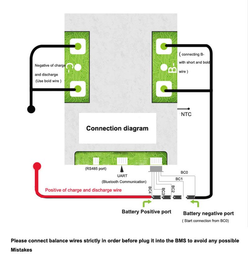
Here is the diagram for your BMS:
4S-Smart-BMS-connection-diagram-1.jpg


Everything (charge and loads) gets connected to the positive and negative terminals on the right. No need to separate chargers and loads, it achieves the same thing internally.
 

DiploStrat

Expedition Leader
Just to be pedantic, the wiring diagram you provided (the same as provided by Overkill Solar) disconnects the battery from both loads and chargers at the same time. The argument is that, at least in marine applications, you do not want to disconnect charge sources merely because the cell voltage (for example) dropped too low or, conversely, disconnect loads, just because the charge voltage was too high.

I think that this all goes back to survival critical systems on a boat. In our case, losing access to the toaster because the BMS does not shut down. So, after wasting a day worrying about all of this, I will relax! :cool:
 

Rando

Explorer
Just to be pedantic, the wiring diagram you provided (the same as provided by Overkill Solar) disconnects the battery from both loads and chargers at the same time. The argument is that, at least in marine applications, you do not want to disconnect charge sources merely because the cell voltage (for example) dropped too low or, conversely, disconnect loads, just because the charge voltage was too high.

I think that this all goes back to survival critical systems on a boat. In our case, losing access to the toaster because the BMS does not shut down. So, after wasting a day worrying about all of this, I will relax! :cool:

No it doesn't. This is where the magic with the MOSFETS inside the BMS comes in - they work like an ideal programmable diode, they can selectively prevent current flow in to or out of the battery based on an over or under voltage situation. I agree that this is not intuitive. This is how battleborn and all the rest of the drop in batteries with just one set of terminals work.
 

DiploStrat

Expedition Leader
If so, that is cool, but have you got a kindergarten logic flow chart that shows how that works; it is above my level of understanding - I don't see how you can create two different circuits with only two terminals. Again, I'm not arguing, just saying I don't understand. (And I ain't an EE!)

Understanding, of course, that it is probably academic for our purposes.
 

luthj

Engineer In Residence
It depends on the BMS. Not all of them will switch the in/out FETs separately. Some will only switch them together, acting like a standard relay.
 

Rando

Explorer
Here is a half decent diagram of one way to implement a common port BMS (left):

BMS-simultaneously-charging-and-discharging.jpg


This assumes some electrical knowledge. But there are three states:
1. Normal operation: Both transistor 1 (Q1) and transistor 2 (Q2) are on. Current can flow either way through both, the BMS is acting like a wire.
2. Over voltage (charge) situation: Q1 is still on (and therefore the current can flow either way through Q1) but Q2 is off. This means current cannot flow into the battery, however, current can still flow out of the battery through the body diode on Q2.
3. Under voltage situation: Q2 is on and current can flow either way through Q2. Q1 is off, but notice Q1 is installed in the opposite direction as Q2, so now current can flow into the battery through the body diode on Q1, but not out of the battery.

Hopefully that helps. Easiest way to think about this is a programmable diode or one way valve which the BMS can switch to be both ways, in only or out only.

It really is a the most elegant way of doing this, as you can add a charge or discharge source, or bi-directional source any where to your wiring without having to separate your buses. There is also almost no quiescent current draw or moving parts.

PS we should probably take this discussion to its own thread as luthj is not using a MOSFET based BMS.
 
Last edited:

luthj

Engineer In Residence
PS we should probably take this discussion to its own thread as luthj is not using a MOSFET based BMS.

Please do. I am sure there are plenty of curious minds who would miss it buried in my thread.

------------------

The Orion BMS uses open drain outputs to control stuff. Since the RBS uses a 12V (open source) trigger, I needed to invert the signal. I also wasn't sure if the RBS would exceed the Orion control current limit when changing states.

I grabbed some cheap P channel mosfets and made up a quick switch circuit. There are three channels. One for the main disconnected, one for the alternator charge relay, and another for the heating pad. Though the heating pad is around 4.5A, so it may be near the limit of the mosfet with the smaller heatsink. I will watch it.


1598651415144.png


The current sensor should be arriving on Monday. I will get the mosfet switch board wired in tomorrow, and I can do my commissioning charge and configure the chargers. I was lazy and didn't do a top balance on the cells. So I may need to manually bleed some charge off the high cells. I have a couple 25W 1 ohm resistors with alligator clips, so I can manually balance that way.
 

DiploStrat

Expedition Leader
Perhaps there should be a care-and-feeding-of-a-BMS, or how-your-lithium-battery-wiring-does/does not/should/should not-differ-from-lead acid thread.

In any case, I am off to digest the wiring diagram with an adult beverage.

EDITED TO ADD: OK, the "diode" light bulb just went off. Got it. Still doesn't address the alleged issue of direct connection of chargers to loads, but methinks that this is not really an issue on most overland trucks. Thank you!
 
Last edited:

luthj

Engineer In Residence
Doing a commissioning charge on the pack. Put in 280AH at 120A, then dialed back the charge from 120A to 35A. Looks like I have one cell group thats higher than the other three. 3.39V vs 3.47V currently. Thats probably around 10-20% imbalance, but just guessing based on some LFP logging others have done. At 35A I can shunt about 90% of the current around this cell with my 3x 1 ohm resistors. Going to take a while though. 10% is 56AH, and 29% is 112AH. Maybe I should get another resistor soldered up...
 

john61ct

Adventurer
The two conditions for putting it off as long as possible are:

A. Terminate charge when the first cell (likely the weakest link) hits

3.45Vpc if holding that for more than a few seconds (CV / Absorb cycle)

between there and 3.50Vpc (using HVC, no CV stage, voltage depends on average C-rate, lower if slower, higher OK when charging faster, say above 0.2C)

Going higher voltage after the above SoC points (user defined 100% Full) adds very very little usable discharge capacity, most "input Ah" is really just higher resistance stressful heat production internally, aka "surface charge"

and B. do not allow discharge termination to be based on pack level voltage, need a per-cell LVC

Stop before 3.10Vpc at low average discharge rates, maybe down to 3.00V if you get above say 0.5C

The sooner (higher) you stop the better for longevity, the difference between 80% and 90% average DoD can mean doubling the lifespan.

Compared to with, less / less frequent balancing required is IMO really just a minor fringe benefit.

The shorthand for all this is "avoiding the shoulders", and actually is sacrificing a **lot** less range / cap utilization than the IMO silly "80/20 rule" you sometimes come across.

Sorry if all the above is already known to you personally, just posting as general FYI to the community.

Haven't fully parsed this whole thread in detail, but wow, really great contribution here, thanks!
 

john61ct

Adventurer
Forgot to mention, I'm sure a quality BMS like that Orion lets you set the automated "start resistance balancing" voltage setpoint down to 3.38Vpc or even earlier, at least well below your desired stop-charge setpoint.

With cheaper BMS that don't, people think therefore they "should" set their stop charge higher , maybe even higher than 3.55Vpc, in order to let the BMS finish balancing.

This in fact increases the **need** for more drastic and frequent rebalancing! And shortens cell longevity.

Better in that case to never mind balancing with such a BMS, just use its (hard coded at extremes) protective functions as failsafe redundancy

and choose another of the many ways to do proper balancing at your selected voltage / SoC level

rather than letting the charge profile be dictated by a poorly designed cheap BMS.
 

luthj

Engineer In Residence
Your correct, the Orion Jr gives me full control over balancing. Right now it set to balance when any cell is over 3.25V, and bring all cells within 5mv. It will do this regardless of charge/discharge.

Since my rig will be occupied full time, time above 3.4Vpc is very minor. I may go with a lower charge voltage in the 14.0 range, and do a weekly/monthly run to 14.2V to complete a balance. The BMS can only balance at 150mA, so it needs a bit of time as the cells age.
 

Forum statistics

Threads
188,215
Messages
2,903,929
Members
229,665
Latest member
SANelson
Top