From Freightliner ambulance to RV - we hope!

rlrenz

Explorer
And here's a WORD copy of the side wall data:

The corners of the modular body shall be constructed of an extruded hollow aluminum shape. The cavity of this hollow shape shall be no larger than necessary to provide a solid connecting point for the horizontal structural members. Its design must allow for a minimum of six (6) inches of continuous weld where each horizontal structural member abuts the corner extrusion. This extrusion shall have an equivalent wall thickness of .125 inch. The corner extrusion shall have at least one (1) internal wall gusset of at least .188 inch high and .125 inch wide running the entire length of the extrusion. This requirement is to reduce the possibility of the extrusion bending, twisting or suffering other deformation when impacted or otherwise stressed.
The side assembly shall be reinforced with square aluminum extruded structural on an average of twelve (12) inch centers. These structural members shall be 2" x 2" extruded box tubing with an equivalent wall thickness of .125 inch. To minimize the possibility of the extrusion bending, twisting or suffering other deformation when stressed the extrusion shall be designed so that each of its three (3) walls incorporates an integral wall gusset of at least .125 inch high and .125 inch wide running the entire length of the extrusion. On the fourth (4th) wall of this extrusion, facing the interior of the body, an integral wall gusset of at least .1875" thick and .375" wide shall run the entire length of the extrusion. This gusset is to provide additional strength as well as to serve as a mounting point for internal equipment or structures. These structural shall be MIG (metal arc inert gas shielded) welded together to form the body's "roll cage".
To provide additional structural integrity in the body's corners where the side wall assemblies abut the front and rear wall assemblies there shall be horizontal gusset structures consisting of a rectangular tube measuring .125" x 1" x 2" x 6" long.
To ensure full weld penetration the vertical wall extrusions shall have a 45 degree "weld bevel" on all four (4) corners of the extrusion. This "weld bevel" can be part of the extrusion design or manually ground off the extrusion prior to assembly. In either case the extrusion's wall thickness shall be a minimum of .125 inch at the corner's bevel point. Extrusions with 90 degree corners are NOT acceptable.

The skin covering the front, side and rear walls shall be a single .125 Aluminum sheet with an alloy and temper strength of 5052 H32 for strength, ease of welding and corrosion resistance. Modular bodies fabricated from "multi-piece" front, rear or side skins are not acceptable to this Agency. Where the skin contacts the corner extrusions or the roof rail extrusion it shall be MIG (metal arc inert gas) welded. The skin shall be attached to the vertical and horizontal wall structural with VHB (Very High Bond) adhesive to allow flexibility in the wall assembly. In no case shall screws, rivets or other mechanical fasteners be used to attach the skin to these structural members.
 

Ozrockrat

Expedition Leader
Hmm I don't remember seeing any specifications like this when I checked out Sportsmobile etc.

That VHB adhesive is a PITA to get apart.
 

rlrenz

Explorer
The specs were from 2004, so it's very possible that older modules may have been welded instead of VHB'd. They were prepared by a supplier to the government who was quoting Medic Master medium ambulances, so the odds are that they were cut & pasted from Medic Master standard specs.

I'm willing to bet that there isn't an RV that could meet these specs (unless it was built from an ambulance...)

It's not a PITA to get apart - it's a PITA! If it's thick enough, a long blade can sometimes cut through the center, but then you're stuck with two fuzzy sides to get off the substrate. It uses an acrylic adhesive, so the usual trick of using a heat gun doesn't do a lot.
 

rossvtaylor

Adventurer
Fantastic info, thanks! And, damn... I knew it was sturdy, and was aware of the requirement that it be able to support the vehicle in a rollover... but these are impressive. We're so glad we went this route.

Thanks for taking the time to post this, Bob.
 

rossvtaylor

Adventurer
Do you have something like this in mind? (Found on Pinterest.) I have wondered how to lift such a truck on the road to change tyres.

d5a26f5473e522d79ce452208269f1b1.jpg

Well, we weren't thinking of something like that at all... until we saw that! That's sweet and not a very difficult thing to fabricate. That's cool enough that we may reconsider our plan. But, up until now what we had planned was a scissor jack with a hose and remote pump. Basically, we liked the flexibility of the HUMVEE jack that SARCONCEPTS found and showed in his thread: http://www.expeditionportal.com/forum/threads/34294-building-the-Bullet-XV/page38?highlight=bogert

https://www.youtube.com/watch?v=tzxEMbgUkq4
 

rlrenz

Explorer
If you want a decent hand hydraulic pump, I think I have a Greenlee in the garage. I probably got it back about 1980 or so.

Greenlee pump.JPG
 

scooter421

Adventurer
That is not exactly what I had in mind but it looks like a great idea! I was thinking a bit more like crane type out rigger but this might be far easier to get under the truck. Makes perfect sense!

Scooter...
 

Ozrockrat

Expedition Leader
Do you have something like this in mind? (Found on Pinterest.) I have wondered how to lift such a truck on the road to change tyres.

d5a26f5473e522d79ce452208269f1b1.jpg


Sent from my iPad using Tapatalk

Now that would be a cool sump guard. And I already have a hydraulic pump. Ok med truck guys lets do some design work.
 

patoz

Expedition Leader
This is what I was checking in to...

M385.1.jpg

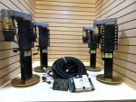
This is an electric combo self leveling/jacking system, with a computerized controller including a remote. There are hydraulic versions available also. It's made by Power Gear for Class A Motorhomes. You park in your campsite, flip the switch, and it lifts and levels your RV perfectly. Or, if you need to change a tire on the road, you can use it to lift just the side with the flat. https://store.lci1.com/products/leveling-stabilization

Here a couple of other manufacturers also:

http://www.bullseyeleveling.com/

http://www.thebigfootleveler.com/


The problem I see with these, other than the extreme cost (3K range), is most of these are designed to mount on the outside of the frame, and on mine the external compartments are jammed right up next to the frame with no room to mount them. It's possible, I could box the frame in the mounting locations, and as long as they didn't stick up above the frame very far, I may be able to mount them like that. However, my frame is only 42" wide, so if I put them on the inside that is going to make a pretty narrow support stance.
 

rossvtaylor

Adventurer
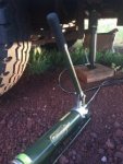
Great ideas, all, and thanks Bob - but, I had already bought a new surplus HUMVEE jack pump. It seems like a nice unit and it's aluminum, so surprisingly light weight.

I hooked it up to the $50 cylinder I bought from Surplus Center and did a quick lift test, after bleeding out the air.

Screen Shot 2016-08-14 at 8.43.46 AM.jpg

It's definitely got enough juice to lift the rig's back end, on a straight lift - 9 inches at a time. I'm not at all sure what we'll end up doing here... On the easy end of the scale, we're considering adding lift points to either the frame or the bumpers (near the frame attachments). Those would be tabs with reinforced holes, through which a cross pin would pass (locking the ram into place)... I already got a grade 5 pin, for some experimentation, from the tractor hydraulics section of our local Tractor Supply store. That lets us use one cylinder and the hand-pumped power unit, which we'd move into position as needed. But, we *might* incorporate some of the permanent ideas tossed around here. Those are slick, but the reality is that it's a lot more work than we can invest at this stage... a permanent jack system would require hoses and a central pump and a lot more time than we can put in right now. We have other things we have to get done first.

One of the first things to address is this:

Screen Shot 2016-08-14 at 8.44.06 AM.jpg

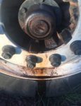
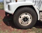
The rig has been parked for a week and I notice this oil leakage from the right front wheel bearing, yesterday evening. I cleaned it up, after this pic, to see where it's coming from and there was oil coming from the center of the rubber bung. It appears to be a pin hole - a vent? It may just be a case of having been overfilled, but until I check further it's not going anywhere.

And, also on the do-it-soon list is the rear bumper. We like the Dynacargo tires we bought enough to plan on staying with them, so we ordered the spare (we'd only bought 4 to start, in case they were crap). It will arrive tomorrow and part of the bumper will be a mount, with raising/lowering capability, for the spare. So, in prep for that, we picked up a 6x4-inch 1/4-inch wall, 8-foot long section of steel rectangular tube.

Screen Shot 2016-08-14 at 8.49.45 AM.jpg

More work ahead!
 

Ozrockrat

Expedition Leader
One of the first things to address is this:

View attachment 361236

The rig has been parked for a week and I notice this oil leakage from the right front wheel bearing, yesterday evening. I cleaned it up, after this pic, to see where it's coming from and there was oil coming from the center of the rubber bung. It appears to be a pin hole - a vent? It may just be a case of having been overfilled, but until I check further it's not going anywhere.

More than likely over filled. Just drain and refil to specification and keep an eye on it. Now from memory about the only specification is for the viscosity not the amount of oil. You fill it to the level indicator of the cap. (I have a spare set of seals here because of the same issue. Bought them because I thought I had a seal leaking problem and it was only an overfill issue).
 

rossvtaylor

Adventurer
I've taken the week off work, and a couple of days home are allowing some progress on the rig. Here's the short version of what's new:

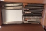
First, a double order of stainless steel off-cuts arrived from OnlineMetals.com - $20 for 20 pounds of assorted grab box fun, seems like a pretty good deal. There's some good stuff in there... solid rod, thick-wall tube, bar and angle, and lots of plate/sheet. Most of the sheet pieces are thin, but a couple are 1/8-inch or a bit more. They'll cut up nicely and become our solar panel roof mounts.

Screen Shot 2016-08-24 at 5.53.03 PM.jpgScreen Shot 2016-08-24 at 5.53.23 PM.jpg

I was going to get all fancy and make tilting racks... but, nah. We can add another panel, if we need, for less than it would cost to add tilt.

Second, I took off the big and somewhat bent rear bumper. I also took off the front bumper, so that I can fabricate and install the winch mount.

Screen Shot 2016-08-24 at 5.46.41 PM.jpgScreen Shot 2016-08-24 at 5.47.48 PM.jpg

Even though it will protrude forward, due to the winch, the new bumper will not be as low - that will help with the front approach angle. And, getting rid of that rear ambulance step bumper will help a lot. As will cutting out this...

Screen Shot 2016-08-24 at 5.47.13 PM.jpg

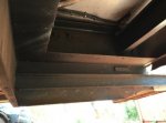
That, my friends, is the rack into which the hydraulic lift gate slid. It hangs down a good 10 inches and, tomorrow, it's coming out.

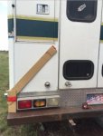
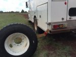
While I'm working, it's time to start getting serious about the rear bumper. I've got a section of 6x4 1/4-inch wall rectangular tube. It's beefy. I've been chatting a bit with my fellow Arizona medium duty ambulance buddies (Ozrockrat and Scooter) and have gone through a few changes to my plan for the spare tire holder. Oz made a good suggestion about dynamic loading and he also showed me a video of a military tire carrier, which "rolls" off to the side. My original plan relied on two beefy 3/4-inch pin hinges, and it would swing down differently, but after seeing that system I've made a pivot. Now, I'm going to "roll" the carrier off to the side. The base will be well reinforced and made in a way that it wraps the bumper tube, so the pivot pin isn't loaded. And I'll include an additional support arm (not shown in cardboard...).

The red tape marks the center of the wheel, and I can still open the right door without moving the tire.

Screen Shot 2016-08-24 at 5.48.59 PM.jpgScreen Shot 2016-08-24 at 5.48.40 PM.jpg

And, finally... the project I've been putting off. Removing the reflective striping, so that we can prep for paint and bed liner. There are 3 (damn yes, three!!!) layers of reflective striping. It's got blue stripes, yellow, another blue, and green over the top. I'd heard this stuff was hard to remove. The heat gun didn't even touch it. So, Whizzy Wheels to the rescue. Damn, if the inventor were here I'd hug him... Now, this is not a quick process at all. With the three layers, it took two wheels (and about 4 hours) to remove about a third of our striping. Amazon will have another 4 here on Friday, so I can finish up this weekend. Messy, but we're so glad to be making progress on this part.

Screen Shot 2016-08-24 at 5.49.16 PM.jpg
 

rlrenz

Explorer
Welcome back from wherever you were!

Some observations/thoughts/comments:

--I noticed that you have 10-bolt wheels. Both MNtal and I have 8 bolt, so the 10-bolt may have been spec'd by the end-user. Interesting.
--We seem to all think alike on rear bumpers - MNtal and I have been planning to build 2 at once, with 4x4 - 4x6 x 1/4" box tube as the basic element.
--I'm a little amazed that your reflective stripes are hanging on as well as they are. Mine were applied by Medic Master, who then sprayed clear coat over the lettering and stripes. Despite the clear coat, they still came off fairly readily.
--I like your cardboard mockup. No matter what your calculator tells you, nothing compares to a full size replica.
--I had thought about a pivoting spare tire holder mounted on the rear bumper, but I KNEW I'd wind up at an angle, or that I'd need to open the rear doors often. When I found out that my spare would fit the rear compartment by 1 inch, my decision was made. I like your plan to swing the tire down to the ground to save your back from trying to lift one down.

If you need a hoist for the spare tire, I have a 250# capacity CM chain hoist floating around here.
 

rossvtaylor

Adventurer
Bob, you've got all kinds of spare stuff! Thanks for the offer - I've got a couple of chain hoists. Last weekend, I used those to pull 120 feet of 2-inch steel pipe out of our well. But, for this, I'm going to put a small ATV-sized winch under the back end. It will let me raise the tire and also lift things into the back of the rig, when we're hauling something heavy.

Regarding the bumpers... yes, the three of us here in AZ are conspiring... uh, I mean, collaborating on bumpers. They may end up slightly different, but it seems like all three of us want 3 receiver tubes, shackle anchors, and a tire carrier. We're each working on designs and we'll have a bumper welding party at my place. If you and MNtal weren't so darned far away, you'd be welcome to come.

And as far as the cardboard goes... CAD for the low tech crowd. I think it was Oz who called it Cardboard Aided Design. :)

I'll post pics and build progress as I get to fabricating.
 

Forum statistics

Threads
188,296
Messages
2,905,089
Members
229,959
Latest member
bdpkauai
Top