pappawheely
Autonomous4X4
Nice, ambitious but well worth the effort for something unique.
Absolutely, just sharing a little trick for someone going out and buying steel. I wish I could see the pictures at work, stupid firewall.
But I have built a few plate style bumper and a few tube style, I gotta say plate is easier with basic tools. I am leaning towards all plate in the centers (frame rail to frame rail) and tube on the ends to keep some weight down.
Very nice work.
Nice, ambitious but well worth the effort for something unique.
Why didn't I build a normal square box bumper! Gaaah trying to get these triangle pieces to line up is a mess. But I'll get it to work.
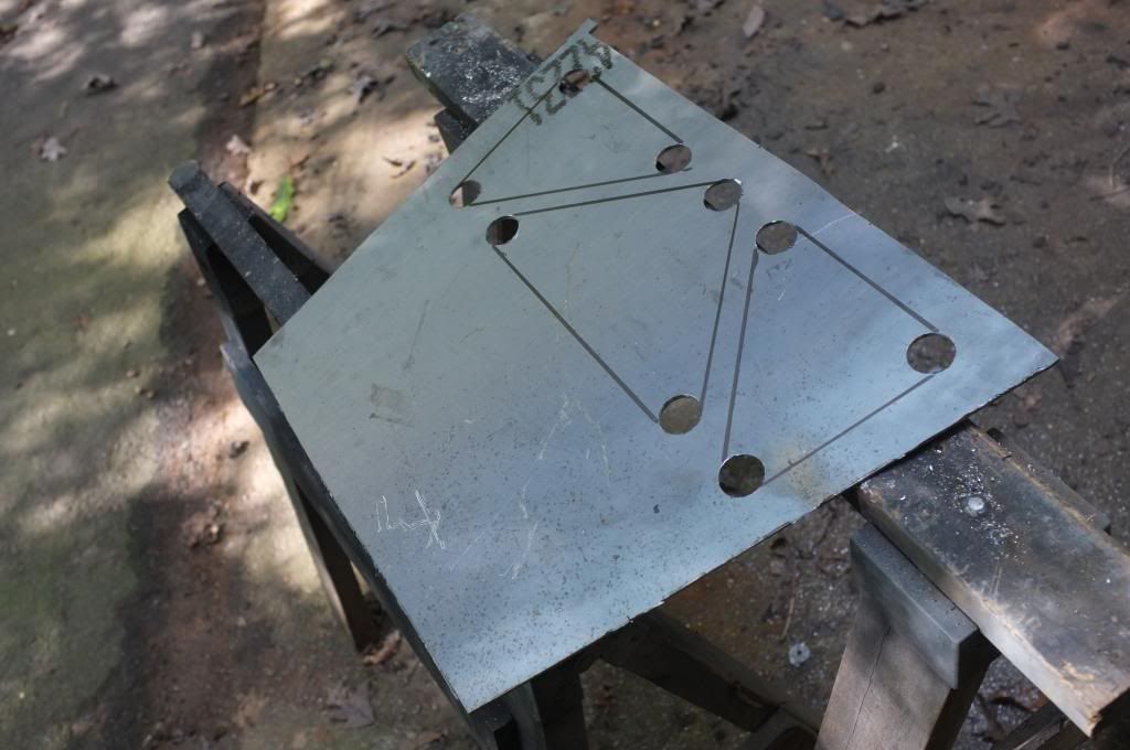
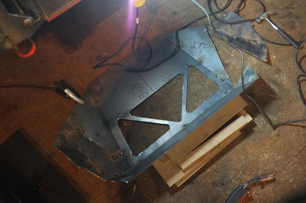
I did some more work on the bumper yesterday. I started with cutting out the vents in the front skid. I used a 1" drill to do the triangles corners and then use the grinder with a cutting wheel to do the cut outs.
![]()
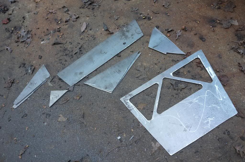
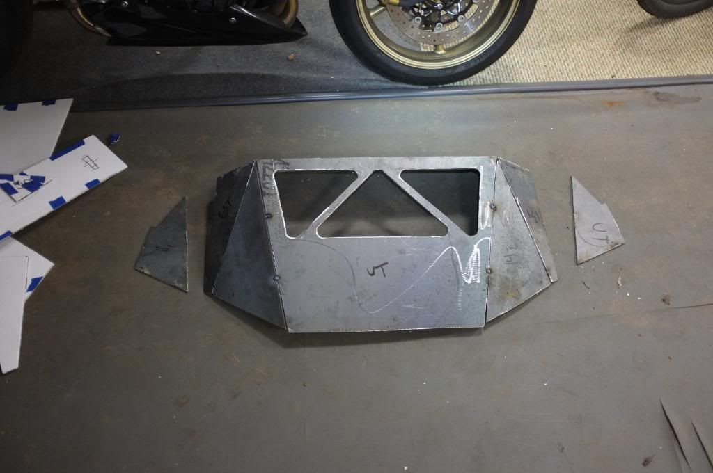
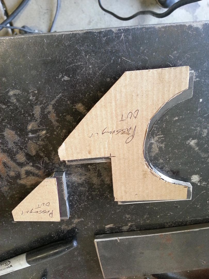
Then I moved on with the grinding wheel and grinded down all the edges and straighted them out. Here are all pieces ready to be assembled.
![]()
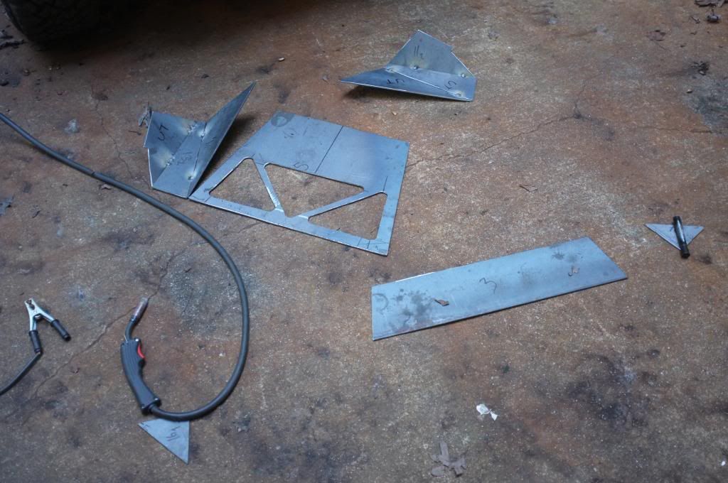
I started tacking it together on the ground before mounting it to the truck.
![]()
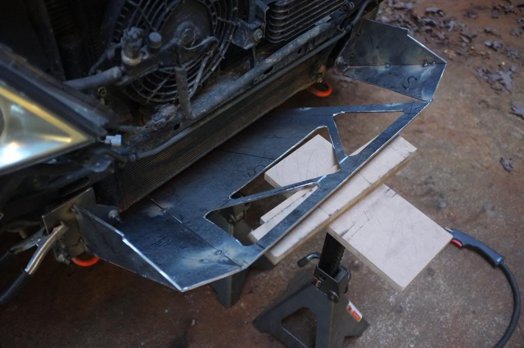
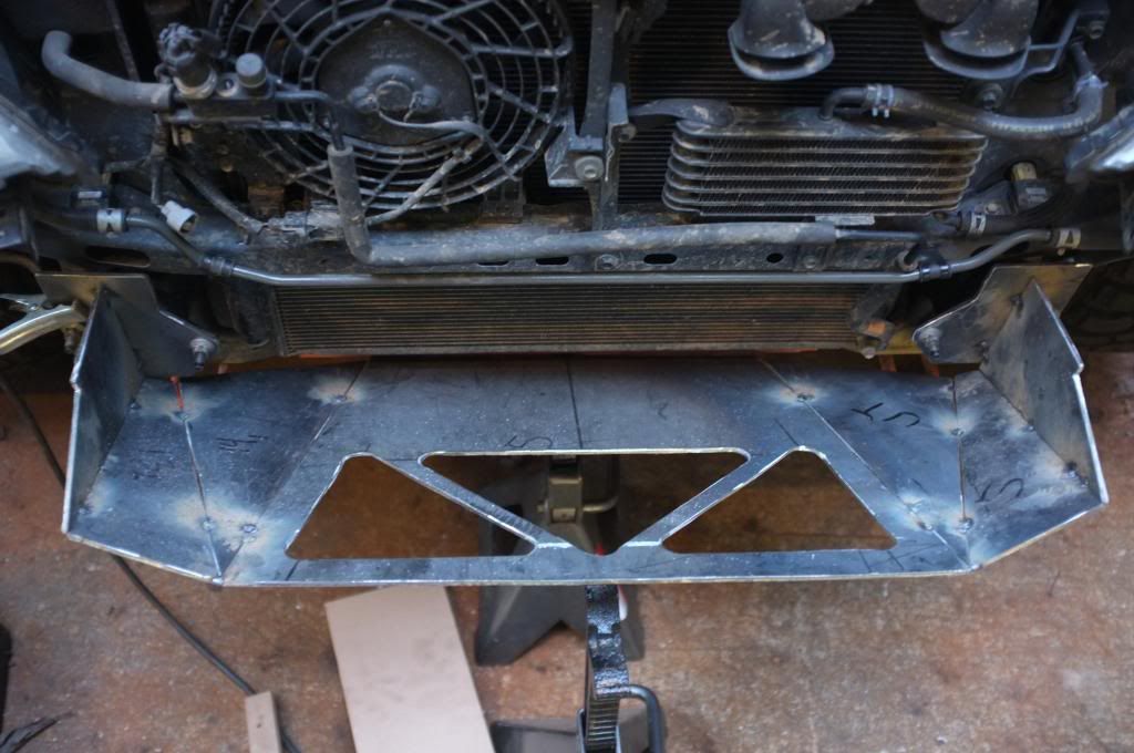
Once on the truck I just added piece by piece to get the complete assembly together.
![]()
I measured both once and twice. The "box" is nice and square but there wasn't a perfect symmetry on both sides. So I cut the weld spots and gave it another shot, this time I did the entire assembly on the ground.
![]()
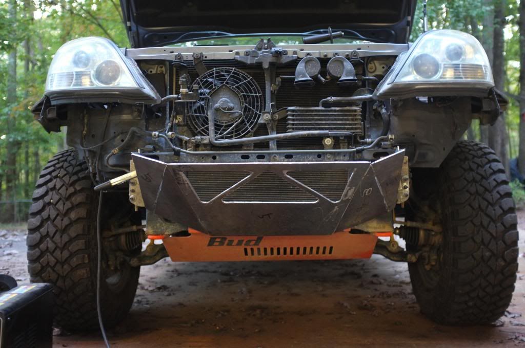
Its still not perfect. So I will most likely chop it up AGAIN and see if I cant get it lined up better. I knew it was going to be hard getting all these triangles to line up and get everything perfect, but not this hard. I should have taken more measurements of the mock up then I did. Aaah well I will just keep on trying.
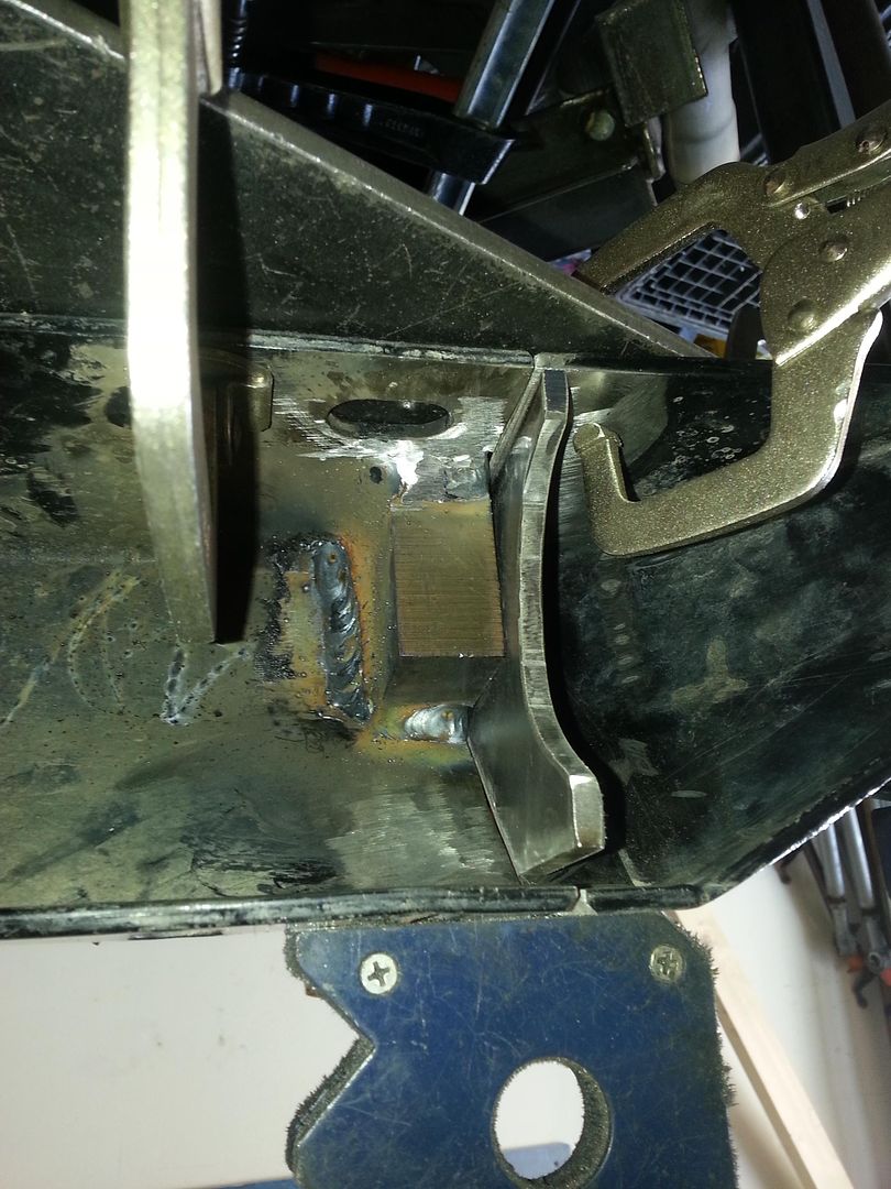
This is how it looks right now.
![]()
![]()
![]()
To be continued...
I think we can all appreciate someone using basic hand tools for this kind of project. I do like the method used to template out the design. The whole cut thing becomes very fun depending on your eventual kerf cuts. Seeing the step-by-step pics is definitely helpful as it speaks to the totality of the time/effort involved.
On an earlier post you showed a potential location for a tow point. It looks like it would be a tab type similar to the following, is that right?
![]()
If so, then I'd suggest (considering the stage you're in) to solidify their location and how integrated to the bracket mounts. Us fullsizes can't afford skimping on these. It looks like you'd make out great with a cross member centered on the bolted brackets (i.e., 2x2x.25" square tube or similar). Then that tab/clevis can be solidly welded to it or rather yet integrated in it. Then your side plates, looks like #11 and #13, can be tied into them. This would help your centering up.
Not at all saying it's bad since you're not complete, as I'm just tossing out the tow point factor and where you are. Keep it up!
Just hope nobody likes it enough to ask you to build another, LOL.
You're making me want to buy a welder. I was planning on having all this done, but I almost wanna do it myself now.
Instead of using a full sheet of steel, I start with steel strap in various widths, 6" 8" 10" etc. It's usually loads cheaper and you have a bunch of factory edges to work with.
YES! That is pretty much exactly what I am planning on doing. I'm going to have a cross member connecting to the mounting plates and the 2 side plates. I will be using a 1.75"x 0.120 DOM tube I have as a cross member. And then weld the tabs to the reinforced tube.
Actually I might go on your approach. Tack weld the side plates to the mounting plates with a "good" angle inboards. Add a cross member. Fix the skid plate where I want it and then "fill" out the gaps between the skid plate and the side plates by adjusting the plates I have cut out already to get it all to fit.
Probably the easiest way to get it straight and square.
Thanks for sharing your ideas/thoughts!
//Marten
One thing to keep in mind with strap is that it's pretty much always hot rolled A36. Plate/ sheet on the other hand can be had in cold rolled 1018. Not a huge deal but the surface is nicer on cold rolled and the grain of the steel holds up better to bending if you are press breaking any parts.
I'm not familiar with the potential weight of your rig, 5K lbs unladen? Just curious.
I saw in your OP the pictures of the fairlead access and the box representation of the winch itself. Do you have your winch plate cut or available at this point? It should be included as part of your x-member and box-in. I'd go larger on the DOM (OD size if possible) you mentioned, but since you'll basically make it integral to the entire shell box that is good. I'm an ANSYS user. Here's an example of helping a buddy of mine using those those same tow tabs, shell bumper, and the needed reinforcement.
Mockup and initial thoughts on gusset and bead placement.
![]()
Gussets cut
![]()
Actual burn in started. It's burned in on all available edges/surface of the tow tab so that it will not move in any direction.
![]()
An early rendition of his front end to show what the factory setup can do by simulating 6K lbs on a single bolt. Don't get too hung up on this as it's a very simplified and conservative representation.
![]()
Hopefully more ideas to add already to yours.