JRhetts
Adventurer
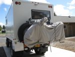
Several people have PM'd me asking for more detail on the rear rack we fab'd for our vehicle. Today I was inspecting the welds and running gear in anticipation of my departure in 2 weeks for a 3-month trip in the Yukon, and this gave me a chance to take some more detailed pics. I hope they provide the info that you have been asking for.
My goals for this rack were:
1. carry two mounted tires
2. raise and lower them safely and conveniently [they weigh almost 200# each, so manual power was not realistic]
3. carry my TW200 motorcycle safely
4. raise and lower the bike safely and conveniently
5. attach the bike securely but also have it quick and convenient to deploy and store it
6. 'overdesign' it so that there is minimal chance of failure or breakage
I began with a great v.1 tire carrier built by Darren Fink. But usage revealed some things I wanted to improve on:
1. add the motorcycle carrier
2. increase the length of the sliding arms so that on level ground there was a 12" overlap still inside the fixed arms [I had occasion to lower the tires on ground that sloped down away from the rear wheels — I discovered that I only had about 1/2"—1" of overlap and that the sliding arms could have disengaged from the fixed arms and caused serious damage to equipment and/or bystanders.]
3. strengthen the attachment of the fixed arms to the frame.
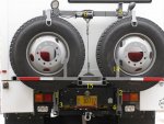
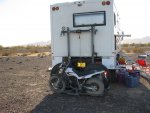
[ABOVE] is the overall unit. [see also http://www.expeditionportal.com/forum/threads/54223-fuso-4x4-rebuild?p=1054538#post1054538
post 135 and following for other pics and information].
It consists of two parallel uprights [1,2], fixed to the frame at the bottom [3,4] and tied together by a crossbar [5] at the top [i.e., where the winch is mounted - 6].
The winch is rated for 2000#. The total weight of the moving parts [rack+tires+m-c] is approx. 1000#, but with two pulleys the effective load on the cable is one third of that. So the winch and cable are not anywhere near maxed out. On the other hand, I'd certainly be screwed if the winch/cable/pulleys failed — in either the up or down position — so I carry a complete replacement winch/cable/pulleys which could be swapped in in a matter of minutes.
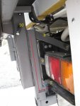
[ABOVE] The lower "L" of the fixed arms [red line] inserts and is bolted into a piece of square stock [color black - 7] which is welded to a piece of plate that is bolted to the frame. Two diagonal straps [8,9] also bolt to the frame to give 'anti-sway' support. [Thus removal of 8 bolts allows the whole rack to be removed from the vehicle, tho it is an awkward procedure that I would not relish doing in the field.]
When the rack is fully up, a pin [10] on each side takes the weight of the rack and the winch is slacked off so it is not stressed during travel. [The prospect of a winch cable failure or the like while underway or while my body was underneath the rear of the vehicle was not something I wanted to experience!!]
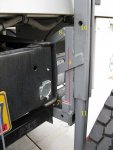
[ABOVE] is a view of the attachment point from the inside. Note that in this pic the rack is fully on the ground; the top of the sliding arm is positioned just below the pin hole [10]. This is the 'extra' travel I wanted to be safe on uneven terrain so the sliding arms could not come fully out at the bottom.
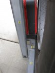
[ABOVE] A piece of sleeved stock [11] is inserted into each fixed upright from the bottom and a horizontal platform for the tires [12] is attached there to. To get the longer travel I wanted to accommodate uneven ground, we reattached the horizontal tire carrier with a vertical "C" bracket [13] that travels in the groove we cut in the face of the fixed tube.
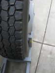
[ABOVE] On the outside of the tire rack, we added vertical pieces [14] to keep the tires from 'just falling out when the rack is resting on the ground — this became important when we added the m-c carrier and did not want to have to wrestle the tires out of the way when driving the m-c onto the carrier.
Back in the first picture, you can see the thicker lower stock [15] we added to the original tire carrier to reinforce the attachment at the "C" bracket and to support the cantilevered m-c weight on its carrier.
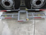
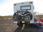
[ABOVE] The m-c carrier inserts into the heavy stock arms and is pinned on both sides. The outside rectangles are sized for the TW200's tires, [16] front and [17] rear. The vertical bars [18 and 19] have nuts welded in the tops, so that a bolt can be inserted thru each footpeg and quickly tightened. These are unnecessary since the tires sit so deep in their respective rectangles, but the bolts make it rock-solid(!) and give me peace of mind when we are rocking' and rollin' up a dry streamed or down a powerline with no road.
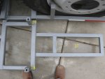
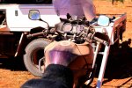
[ABOVE] A more detailed look at the footpeg attachment points.
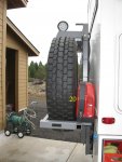
[ABOVE] This pic is from the side — shows where two 5-gal jerry cans [20] (one on each side) ride.
The final 'feature' of the rack is that it is the attachment point for the BBQ - a very important piece of the overall puzzle!
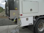
[ABOVE] First step is to:
put up the shield for the gas can [21]
plug in the gas line to the quickcoupler [22]
insert the BBQ support arm into the rack [23]
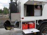
[ABOVE] Second step is to:
attach the BBQ [24]
open the upper locker door to reveal an overhead light [25]
open down the lower box door to establish the table [26]
Third step is to cook and enjoy an adult beverage.
While I am doing that, I hope you are getting ideas about solutions for yourself.
Happy Trails.
My goals for this rack were:
1. carry two mounted tires
2. raise and lower them safely and conveniently [they weigh almost 200# each, so manual power was not realistic]
3. carry my TW200 motorcycle safely
4. raise and lower the bike safely and conveniently
5. attach the bike securely but also have it quick and convenient to deploy and store it
6. 'overdesign' it so that there is minimal chance of failure or breakage
I began with a great v.1 tire carrier built by Darren Fink. But usage revealed some things I wanted to improve on:
1. add the motorcycle carrier
2. increase the length of the sliding arms so that on level ground there was a 12" overlap still inside the fixed arms [I had occasion to lower the tires on ground that sloped down away from the rear wheels — I discovered that I only had about 1/2"—1" of overlap and that the sliding arms could have disengaged from the fixed arms and caused serious damage to equipment and/or bystanders.]
3. strengthen the attachment of the fixed arms to the frame.

[ABOVE] is the overall unit. [see also http://www.expeditionportal.com/forum/threads/54223-fuso-4x4-rebuild?p=1054538#post1054538
post 135 and following for other pics and information].
It consists of two parallel uprights [1,2], fixed to the frame at the bottom [3,4] and tied together by a crossbar [5] at the top [i.e., where the winch is mounted - 6].
The winch is rated for 2000#. The total weight of the moving parts [rack+tires+m-c] is approx. 1000#, but with two pulleys the effective load on the cable is one third of that. So the winch and cable are not anywhere near maxed out. On the other hand, I'd certainly be screwed if the winch/cable/pulleys failed — in either the up or down position — so I carry a complete replacement winch/cable/pulleys which could be swapped in in a matter of minutes.

[ABOVE] The lower "L" of the fixed arms [red line] inserts and is bolted into a piece of square stock [color black - 7] which is welded to a piece of plate that is bolted to the frame. Two diagonal straps [8,9] also bolt to the frame to give 'anti-sway' support. [Thus removal of 8 bolts allows the whole rack to be removed from the vehicle, tho it is an awkward procedure that I would not relish doing in the field.]
When the rack is fully up, a pin [10] on each side takes the weight of the rack and the winch is slacked off so it is not stressed during travel. [The prospect of a winch cable failure or the like while underway or while my body was underneath the rear of the vehicle was not something I wanted to experience!!]

[ABOVE] is a view of the attachment point from the inside. Note that in this pic the rack is fully on the ground; the top of the sliding arm is positioned just below the pin hole [10]. This is the 'extra' travel I wanted to be safe on uneven terrain so the sliding arms could not come fully out at the bottom.

[ABOVE] A piece of sleeved stock [11] is inserted into each fixed upright from the bottom and a horizontal platform for the tires [12] is attached there to. To get the longer travel I wanted to accommodate uneven ground, we reattached the horizontal tire carrier with a vertical "C" bracket [13] that travels in the groove we cut in the face of the fixed tube.

[ABOVE] On the outside of the tire rack, we added vertical pieces [14] to keep the tires from 'just falling out when the rack is resting on the ground — this became important when we added the m-c carrier and did not want to have to wrestle the tires out of the way when driving the m-c onto the carrier.
Back in the first picture, you can see the thicker lower stock [15] we added to the original tire carrier to reinforce the attachment at the "C" bracket and to support the cantilevered m-c weight on its carrier.

[ABOVE] The m-c carrier inserts into the heavy stock arms and is pinned on both sides. The outside rectangles are sized for the TW200's tires, [16] front and [17] rear. The vertical bars [18 and 19] have nuts welded in the tops, so that a bolt can be inserted thru each footpeg and quickly tightened. These are unnecessary since the tires sit so deep in their respective rectangles, but the bolts make it rock-solid(!) and give me peace of mind when we are rocking' and rollin' up a dry streamed or down a powerline with no road.

[ABOVE] A more detailed look at the footpeg attachment points.

[ABOVE] This pic is from the side — shows where two 5-gal jerry cans [20] (one on each side) ride.
The final 'feature' of the rack is that it is the attachment point for the BBQ - a very important piece of the overall puzzle!

[ABOVE] First step is to:
put up the shield for the gas can [21]
plug in the gas line to the quickcoupler [22]
insert the BBQ support arm into the rack [23]

[ABOVE] Second step is to:
attach the BBQ [24]
open the upper locker door to reveal an overhead light [25]
open down the lower box door to establish the table [26]
Third step is to cook and enjoy an adult beverage.
While I am doing that, I hope you are getting ideas about solutions for yourself.
Happy Trails.
Last edited:

