Hey Vortec Guys! / Sierra pickup / Suburban / Yukon etc - Finally has Index!

rho

Lost again
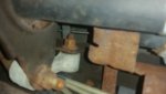
The stab-on heater hose connections at the firewall are a point of failure, especially at high mileage. If you ever bump or dislodge one say when working on the #8 coil pack, their corroded o-rings disintegrate and you'll be raining fluid. I changed them on my missus' Tahoe without removing the intake manifold and it was a terrific pain in the rear to manipulate those connectors in those tight confines. Later on my Sub while doing a knock sensor replacement and seal change, having the intake off already for that (and changing the intake gaskets too), I went ahead and changed both those heater hose connectors while I had much easier access. It's discussed back in the earlier pages of this topic.
water pumps and thermostats are relatively inexpensive and very easy to change on these engines, consider changing it all at the same time, while you are already working on the system.
check out rockauto.com if you aren't already aware of them.

Right on, sounds good. We have all of the service records for this thing so I'm gonna go dig through it to see if it was ever replaced, but I kind of doubt it. I'll add those to the list too. I'll see how the heater hose connectors look, the truck is overall in good shape under the hood and the plastics are in good shape as well. Well, as good as they can be for a 16yr old truck with a 180k on it, lol.
Rockauto is awesome! I've used them for a lot of jeep stuff in the past and will be getting a ton o stuff from there for this truck I'm sure. I've been lucky that my JKU has been very trouble free in the past 7 years I've had it, other than trans/clutch stuff.

I guess another Q I have... Anyone rebuilt their G80 diff? Or what should I expect from these things in terms of durability/function. The one in this truck seems like it works, as it does a lot better off road than a 2wd has any right to, but I want to make sure this thing can still function down the road and if that means pulling axle shafts and replacing clutch packs and stuff to rebuild it, then so be it.
 

rayra

Expedition Leader
There's vids and pics of people going to simple hose clamp connections there. It works. The stab-on (whatever they're properly called) connectors are for ease on the assembly line. Takes no time to put them on. It's the getting them off that sucks. And on the Subs particularly as they're T-connectors, also feeding the coolant runs to the rear AC. The pickups just have a single straight connector.
 
The G80s (made by Eaton) are plenty tuff and work well but if it got to the point where I had to rebuild mine I’d opt to replace with a Detroit TruTrack. Gears rather than friction packs and virtually transparent in operation.
 

rho

Lost again
The G80s (made by Eaton) are plenty tuff and work well but if it got to the point where I had to rebuild mine I’d opt to replace with a Detroit TruTrack. Gears rather than friction packs and virtually transparent in operation.

I have truetrack in my JKU and its fantastic. I've thought about one for the truck, it might be feasible to swap the thing when it comes time but its a bit of a challenge as I don't have a ton of space to do internal gear work. On the other hand, setting the backlash on something like that isn't hard and I have the tools for it at least. Ya know, requisite torque wrench, dial indicator, micrometer, etc etc (unlike stuff for the pinion bearing and shims, where i just don't have the tooling/presses/strength to deal with that stuff).
 

rayra

Expedition Leader
Made the gang-sawing jig for turning hockey pucks into torsion crossbar mount bushings. But I have no pucks to saw, why you no deliver, Amazon?

bushingjig01.jpg
bushingjig02.jpg
bushingjig03.jpg


Pucks will get sliced from 1" thick to 3/4" - dangit forgot to make that jig, just a 3/4" plank with a 3"dia hole thru it. Fence set 3/4" from the saw, thickness of the plank. Puck inserted in the hole, up against the fence, plank and puck run thru the saw. Viola, puck height shortened to 3/4" without having to hold the dang thing.

Then drill a 1"dia hole thru the center of the pucks.

Then mount the four pucks on the pegs on one side of the jig. The 3/4"x1" wood strips will get set snug on the inboard part of the pucks, then screwed into the center handle of the jig.
The bottom of the jig was trimmed down 5/8" from the pegs on one side and 7/16" on the other. Just set the loaded jig on the table saw and snug the fence up to it. Put the pucks on the 5/8" side and raise the blade height taller than the pucks and trim their outer diameters down to 2-1/4". Make a saw pass, then turn the pucks and cut them again. Again and again until they are trimmed down.
Set the saw blade height to 7/16" above the bottom plate of the jig.
Then dismantle the jig and swap pucks to the other side/row of pegs, re-attach the handle / clamp and repeat the sawing passes, to create the narrower barrel of the bushing.

If I thought it thru more I might have made the jig a little different, but didn't want to spend much time on it. And I suppose someone will find some purpose-made or readily adaptable bushing that will work just fine, just as I finish making the first set of improvised ones.
 

jgaz

Adventurer
Made the gang-sawing jig for turning hockey pucks into torsion crossbar mount bushings. But I have no pucks to saw, why you no deliver, Amazon?

bushingjig01.jpg
bushingjig02.jpg
bushingjig03.jpg


Pucks will get sliced from 1" thick to 3/4" - dangit forgot to make that jig, just a 3/4" plank with a 3"dia hole thru it. Fence set 3/4" from the saw, thickness of the plank. Puck inserted in the hole, up against the fence, plank and puck run thru the saw. Viola, puck height shortened to 3/4" without having to hold the dang thing.

Then drill a 1"dia hole thru the center of the pucks.

Then mount the four pucks on the pegs on one side of the jig. The 3/4"x1" wood strips will get set snug on the inboard part of the pucks, then screwed into the center handle of the jig.
The bottom of the jig was trimmed down 5/8" from the pegs on one side and 7/16" on the other. Just set the loaded jig on the table saw and snug the fence up to it. Put the pucks on the 5/8" side and raise the blade height taller than the pucks and trim their outer diameters down to 2-1/4". Make a saw pass, then turn the pucks and cut them again. Again and again until they are trimmed down.
Set the saw blade height to 7/16" above the bottom plate of the jig.
Then dismantle the jig and swap pucks to the other side/row of pegs, re-attach the handle / clamp and repeat the sawing passes, to create the narrower barrel of the bushing.

If I thought it thru more I might have made the jig a little different, but didn't want to spend much time on it. And I suppose someone will find some purpose-made or readily adaptable bushing that will work just fine, just as I finish making the first set of improvised ones.
Clever! Especially like the “hands outta harm’s way features”
 

rayra

Expedition Leader
After I posted the above I checked my email and found a delivery confirmation, they snuck the package on the porch right after I closed up the garage, apparently. So I got right to messy work. Only took about 90mins to get them close enough.

"Everything is proceeding as I have foreseen"

A very messy business. Not recommended for folks who haven't got a good bit of experience being stupid with powered cutting tools. 3-4x things started to bind or grab and I was able to avert disaster.

First off was slicing the pucks down to a hair over 3/4" in height. First one was a botch, as I tried to cut the first one full height in one pass. The 3" hole in the pine plank was a little loose on the puck and the puck leaned over as the saw hit a midpoint, canting the cut. The next puck I put 2-3 wraps of masking tape on its edge for a snug fit in the jig AND I lowered the cutting height to a little over the radius of the puck and made a pass, popped out the puck and rotated 1/3 and stuck it back in secure, cut again, etc, until the remnant wafer came off.

bushingjig04.jpg
bushingjig05.jpg
bushingjig06.jpg
bushingjig07.jpg


Then it was drilling. I measured off a rough center on all the pucks, not much caring for exactness as I was planning to take 3/4" off the total diameter of the puck and had room to be off center. The "milled" puck would be centered on wherever the 1" hole got drilled, anyway. I did a 1/16? 3/32? bit pass first as a guide hole , 'aim small miss small'. Then a 3/16" bit to enlarge those holes. Then the 1" forstner bit, which really made some nice shavings and quick work of the pucks.

bushingjig08.jpg


On to the gang jig! Got the table saw adjusted, checking and re-checking. I set the shaved and drilled pucks on their pegs and then attached the wood bar that would lock them on their pegs. I could have bore down with a clamp before screwing the bars to the jig handle, but decided I wanted to be able to spin the pucks manually without having to dismantle the whole thing for each pass. I found I needed to push down on each puck as they passed thru the blade. Fingers about 3/4" away from the blade. DON'T DO THIS! I think I've already figured out a modified jig setup, using the earlier-mentioned knob-handled bolts. Just make the 'clamp a flat base that reaches to both sides, the handle rising vertically out of that piece, then use the knobbed bolts as both handle mounts and as tensioners. Then it's lock them down tight, make a cut pass, loosen the knobs a half turn, move the pucks, tighten back up and make another pass. If I wind up making sets of these for other folks I'll re-make my jig.

Anyway, first pass was a full height blade pass (blade standing 1/8" taller than the tops of the pucks) to size the overall flange width. I set things to create a 2-1/4" overall width and after a few test nibbles, went at it. Didn't take very long with the gang jig. I spaced the pucks far enough apart that I could finish cutting thru one before the next contacted the arc of the blade. I could concentrate on holding down one puck at a time.
They came out a little flat sided, mostly because I wasn't going to chance spinning them into the saw blade. I can touch them up cosmetically on my big table-mounted sander, but it has zero impact on fit or function.

bushingjig09.jpg
bushingjig10.jpg
bushingjig11.jpg
bushingjig12.jpg


Then it was setting the saw cut height to achieve the 7/16" height of the barrel part of the bushing. Leaving a flange 5/16" thick. These passes were messier and would have benefited from using a DADO blade stack. Maybe I'll try that next batch, if there is one. These I did try spinning as the blade was lowered and over-topped by the flange portion of the pucks. So the barrel section was a little more smooth. And this portion it kinda works a bit like splines. Don't want the bushing too tight or too loose in the steel mounting ring. The polygonal shape might just work well. Won't know for a month or so, when I get around to replacing my lower control arms.

bushingjig13.jpg
bushingjig14.jpg
bushingjig15.jpg
bushingjig16.jpg
 

rayra

Expedition Leader
Then a quick check with the gauge and I'm a lot closer than I expected to get. These should work well when I use them. Smear some silicone grease all over and in them, drill and grind out the old bushing from the mount, recoup and clean up the inner bolt sleeve, stick it in one of the bushing halves and stuff that in the rear side of the mounting ring and slide / drive the other side on. Once it's all squeezed into the mount, bring the crossmember down on top of it and it should all be a snug fit, near to new. ETA make that 'better than new', since there's a proper flange to keep the guts of the mount centered and keep the mount and crossmember steel from banging together. But maybe that factory mount needed that range of fore-aft or up-down pitch motion. I'm gonna find out, some months in the future after these are installed. I'll be watching for rapid wear on the flange or in the crossmember shape. But I won't be a proper test case either. My method of off road travel is slow and easy. Not a lot of rapid or full range motion.


bushingjig19.jpg
bushingjig20.jpg
bushingjig21.jpg
bushingjig22.jpg
bushingjig23.jpg
 
Last edited:

lilkia

Active member
Not that it helps but heres the mount on the 2500. Its alot different.
Did you get the pucks installed yet? How do they ride?
 

Attachments

  • 20190303_165449.jpg
    20190303_165449.jpg
    3.1 MB · Views: 40

rayra

Expedition Leader
It'll be several weeks before I get around to changing the lower control arms and installing these bushings. Have other things I need to see to first. And I don't drive this Sub much so not in a rush to get it done and re-aligned.

That crossmember mount is quite different. But it sure looks like the crossmember itself is the same. If the frame rail an open 'C' shape? The 1500 Sub is completely boxed and most of the plumbing runs down the outside of the frame rails.
 

rho

Lost again
There's vids and pics of people going to simple hose clamp connections there. It works. The stab-on (whatever they're properly called) connectors are for ease on the assembly line. Takes no time to put them on. It's the getting them off that sucks. And on the Subs particularly as they're T-connectors, also feeding the coolant runs to the rear AC. The pickups just have a single straight connector.

Ah, ok. I'll figure out how to deal with em when we tear into it this weekend.

I ended up gettting the bigger radiator with both the trans and engine oil coolers (34" vs 28") by mistake but it looks like all the proper mounting holes/brackets are there in the frame for it, so we're going to just go with it. I need to figure out if this truck has an engine oil cooler or not. It looks like one of the two coolers infront of the condenser is for the power steering with the other being for the transmission fosho.
Waterpump and tstat are on their way as well. My only kind of worry with the bigger radiator is the fan shroud not fully fitting, but it doesn't look like there are a lot of different variations of the shroud for the 5.3 engine... At least in my digging.

I haven't had a ton of time to dig into the mess yet as I got distracted when changing the oil with figuring out what I can do for skid plates under the engine/transmission/front suspension and also what all the un-used brackets and mounting locations and stuff are under the truck.
I'm really curious about what the common chassis parts and mounting locations are between the 2wd coil sprung and 4wd torsion bar suspensions and their mounting locations. The engineer in me can't help but wonder.
@rayra there was some discussion about why the half-tons have all the torsion bar cross members and all that stuff bolting in (torsion bar xmember/lower suspesion moutning points/etc)... I wonder if the frame is common between the two?
 
Last edited:

rayra

Expedition Leader
In the GMT800 series I think the 1500 frame is common across pickups, Tahoe / Sub & Avalanche. GM has a long history of using identical subcomponents anywhere they can across multiple variants and even different vehicle models, if they can. Especially goes for engines, transmissions, brakes..
 

rayra

Expedition Leader
The nearest Energy Suspension 'Universal' bushings I can find are set number 9.9485*, but all four dimensions still have to be reduced or enlarged. But they'd be polyurethane and not puck rubber. About an 1/8" off the barrel, 9/16th off the barrel length, 1/4" off the outer flange dia. and opening the center hole from 7/8" to 1". And the flange at .22" is itself too thin for a snug fit with the crossmember. Needs to be closer to .3125. The reinforced belt I cut the washers from was 3/16"(=.1875"). So you could stack the two poly bushings in and put the rubber belt washer on the forward face of the stack and have a nice snug fit in the crossmember.
I intend to install my puck bushings and see how things go. If they break down, I will probably use my jig and buy the Energy Suspension poly bushings and mod them.


* Energy Suspension doesn't list a torsion bar crossmember mount bushing for the GMT800s. They have a complete front bushing set, control amrs and shocks, and sway bar and sway bar end link kits that look very nice.
 
Last edited:

rho

Lost again
In the GMT800 series I think the 1500 frame is common across pickups, Tahoe / Sub & Avalanche. GM has a long history of using identical subcomponents anywhere they can across multiple variants and even different vehicle models, if they can. Especially goes for engines, transmissions, brakes..

I think in this case the frames are different. All of the 4x4 examples i've been finding have had [ shaped frame rails and our truck has those as well.

503410
I cropped this from some other site that was doing an install, but this is a nice clear photo... the areas in red are what look like the biggest differences between our 2wd and the pictured 4wd. The holes in the transmission crossmember are already there on our truck, as are the contact pads on the frame rails where the torsion bar could contact. The upper mounts are same across models and I suspect the lower mounts have the same interface to the frame...
There looked to be holes in the frame rails on our truck where the rivets would have been for the torsion bar crossmember mounts/bushings, but i'd have to crawl back under there to take more photos and to poke around more and i won't be able to do that till the weekend. I think this might be a viable project after all.

All in all i'm not sure this is ever something i'd do with this truck, but its kind of interesting to look at it from the perspective of badge engineering and where they saw the production line costs could be lowered with common products, I'd guess the 'burbs and burbs had different frames than the trucks because of their higher passenger count requiring a higher GVWR... Hmmm. Plus the general poor ride quality of torsion bars, but If it was something we chose to do it'd be less for ride quality and more for durability, lower maintenance and stronger factory LCA's. 2WD trucks bash through things off-road instead of slowing crawling over stuff so it is something on my mind (plus skids...).
 

Burb One

Adventurer
I think in this case the frames are different. All of the 4x4 examples i've been finding have had [ shaped frame rails and our truck has those as well.

View attachment 503410
I cropped this from some other site that was doing an install, but this is a nice clear photo... the areas in red are what look like the biggest differences between our 2wd and the pictured 4wd. The holes in the transmission crossmember are already there on our truck, as are the contact pads on the frame rails where the torsion bar could contact. The upper mounts are same across models and I suspect the lower mounts have the same interface to the frame...
There looked to be holes in the frame rails on our truck where the rivets would have been for the torsion bar crossmember mounts/bushings, but i'd have to crawl back under there to take more photos and to poke around more and i won't be able to do that till the weekend. I think this might be a viable project after all.

All in all i'm not sure this is ever something i'd do with this truck, but its kind of interesting to look at it from the perspective of badge engineering and where they saw the production line costs could be lowered with common products, I'd guess the 'burbs and burbs had different frames than the trucks because of their higher passenger count requiring a higher GVWR... Hmmm. Plus the general poor ride quality of torsion bars, but If it was something we chose to do it'd be less for ride quality and more for durability, lower maintenance and stronger factory LCA's. 2WD trucks bash through things off-road instead of slowing crawling over stuff so it is something on my mind (plus skids...).

Interesting!!! Never had a 2wd, but I always assumed the suburban/tahoe/yukon/avalanche were all the same. I figured only the silverado 2wd's with the coil front ends were any different.

Unless I'm misunderstanding, I don't think any of the differences changes any suspension geometry or driveline though....
 

Forum statistics

Threads
187,609
Messages
2,895,851
Members
228,596
Latest member
donaldsonmp3
Top