How to make a cheap isolated dual-battery setup for $50

calicamper

Expedition Leader
Dan just from a battery health perspective and ease of use I'm running power to a small 6 fuse box from the controller so I can let the controller manage battery life/charge health. My use will be simple LED lighting and very basic small item charging like GoPro camera, Cell phone etc. So I will be in the 20amp and under range easily. I do plan on inline fuses between my controller and the load wiring to my fuse block as a safety for the controller. The Solar and battery connections I wont fuse those. My primary concern is causing a load issue with the cheap LED gear or a faulty charging hub or ground issue that damages the load side of the controller. So by placing a 15amp or maybe 20amp fuse between the controller and my load items I can prevent any goofy issues were the total load passed through by my 6 fuse block does not blow a fuse. I'm going to run 2 5amp fuses in my block for the two LED power sources they pull about 2amps max tested that will go on each of the two power sources from the fuse block. Then I will run a 10amp fuse on my charging hub via the fuse block. No fridge yet any way ;-)
 

4RunAmok

Explorer
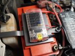
Since you said there will be multiple loads connected - you are going to need some sort of distribution block. Depending on your charge controller it may be difficult to use a large enough wire gauge with the controller - this is why I opted to use blue sea fuse blocks connected directly to the battery with 4AWG since this makes adding a circuit a lot simpler, and each one is fused.

IMAG0027.jpg
4 Gauge wire, 6 inches of length, for a unit with a bus that is only capable of 75 amps max load? And do I see a little 18 gauge wire piggybacked on a 12 gauge wire sharing a fuse?
 

dlichterman

Explorer
4 Gauge wire, 6 inches of length, for a unit with a bus that is only capable of 75 amps max load? And do I see a little 18 gauge wire piggybacked on a 12 gauge wire sharing a fuse?

It's actually rated at 100A total, and yeah there are some double ups just to run a smaller gauge for the switch(s). I think it's 16 not 18 :p

And the 4 gauge might be a bit overkill, but it's what I had on hand with lugs that is rated for it.

http://assets.bluesea.com/files/resources/newsletter/images/DC_wire_selection_chartlg.jpg
 
Last edited:

Dan Grec

Expedition Leader
Since you said there will be multiple loads connected - you are going to need some sort of distribution block. Depending on your charge controller it may be difficult to use a large enough wire gauge with the controller - this is why I opted to use blue sea fuse blocks connected directly to the battery with 4AWG since this makes adding a circuit a lot simpler, and each one is fused.

I'm likely going with exactly the same fuse block, thanks :)

-Dan
 

dwh

Tail-End Charlie
grecy;1835935 It says "Reserve Capacity: BCI: 120 minutes (25 amp discharge said:
to 10.5 volts cut-off[/B])"

So I was assuming that means the battery will cut-off at 10.5v to protect itself.

I think that just means that's where they cut off the reserve capacity test. If that battery had an internal LVD, I think they'd list it as a selling point.
 

4RunAmok

Explorer
It's actually rated at 100A total, and yeah there are some double ups just to run a smaller gauge for the switch(s). I think it's 16 not 18 :p

And the 4 gauge might be a bit overkill, but it's what I had on hand with lugs that is rated for it.

http://assets.bluesea.com/files/resources/newsletter/images/DC_wire_selection_chartlg.jpg

The install is not that different than mine, albeit without the piggybacks.
P3219769r.jpg
I hope I wasn't sounding too critical, but with the close proximity to the battery, we are obviously well situated for amp loads. But it is important to recall the max capacity of the unit, which for some reason, I remember being 75 watts. Looking at their website, they all say 100amp now. Perhaps they've upgraded them.
 

dlichterman

Explorer
But it is important to recall the max capacity of the unit, which for some reason, I remember being 75 watts. Looking at their website, they all say 100amp now. Perhaps they've upgraded them.

Both of mine have been rated at 100amps, so I guess so. Trust me it's a lot better than it was with wires going everywhere(and direct to the battery) and fuses randomly placed. All the doubles are a load and the switch for that load so they're kept together. I've got a second one in the back for the aux battery that's got the solar.
 

dlichterman

Explorer
Talking with Woody, he has spoken of your setup. Maybe one day I'll get to see it in person.

Ah, yeah everyone is always interested in one piece on my setup - the timer relay that I found. The only 12V time delay relays I was finding were direct from China with horrible documentation and questionable build quality, but I found this completely over-engineered for my use one:

http://www.alliedelec.com/schneider-electric-magnecraft-821td10h-uni/70185027/

It has a million(read: ~10) features but I'm just using it to delay the joining for a few minutes to let the alternator charge up my starting battery first. The system hasn't let me down and I'm glad I went with the 200A fuses and solenoid as I've had to self jump.
 

4RunAmok

Explorer
We talked specifically about that. I like those. There's one we use at work from McMaster-Carr that is a sequential relay for using momentary switches placed throughout a vehicle to turn on and off a light from multiple sources. It looks a lot like that.
 

NevadaLover

Forking Icehole
QUOTE Note 2: Since like the crackhead you were in your youth, you'll jump right on any bandwagon driving by, make sure you get a larger charge controller now, so you can hook up more tin foil later, otherwise you'll have to re-buy another controller and then it won't fall under the 'cheap solar' category anymore, kapish?

WOW!! That is the single most ignorant thing I have ever read!!!!! NO, NO, actually that is the single most HILARIOUS thing I have ever read!!!!!! :xxrotflma:xxrotflma
YOU da man!!
 

lminer

New member
This is the best site I have found for learning about this topic. I am new to the forum and hoping for some help. I have read all 54 pages and have a few questions. I have a ‘93 Toyota Dolphin (Toyota Tacoma chasis). There is already an existing isolator for the starting battery and the deep cycle house battery. I want to add an additional deep cycle battery using a Cole Hersee continuous duty selenoid as the two deep cycles are the same type of batteries but different ages. The additional deep cycle is in a sealed box (will be vented to the outside) and has a 12v socket with a fuse in it. This battery will be used to charge a laptop, phones and cameras that have 12v chargers. I don't need the dash switches and I don’t have solar panels. If I need to jump start the battery, I will use jumper cables not the solenoid. I have some questions regarding the original diagrams in the post. With the configuration I need, am I able to use -

- 4GA wire instead of 2GA wire?
- 80A additional solenoid instead of 200A solenoid?
- 80A fuses instead of 200A fuses?
- Do I run the 12GA wire from the additional solenoid to the same location where the existing solenoid is connected?
- Do I have to mount the solenoid under the hood or can I mount it somewhere else closer to the house batteries?
- Also, I’m not sure how I would monitor the additional battery so I don’t drain it too low. Not sure if this battery will be reflected in the battery level panel with the way it will be set up.

Thanks for all the great knowledge and advice on this site.
 

jrfromafar

Adventurer
This route looks like my ticket. I need some 12v happiness in my '72 Alaskan - just enough to run a surveillance cam & floodlight off the back. My rig is a 2014 F250 with camper-tow package so it has the 7 prong in the bumper.


So I have a two-step variation on this thread- a dual battery system for about $12 or less.

1. Tap into the trailer battery charge lead at your 7-pin trailer plug (if equipped)
2. Run it to your aux battery.
3. Run your accessory circuit from the aux battery.

The charge lead is already switched to engine-on, and is designed to charge a trailer battery.
The $12 comes from the cost of the wire that you need to tap into that charging circuit.

*Some say* that the trailer battery charging circuit isn't designed to, and won't, charge a fully discharged battery. That may or may not be true; our trailer batteries (2 @ 6v golf cart batteries) get charged pretty well when we are towing our travel trailer from campsite to campsite. But assuming that it's true, do you ever really need to charge a battery from a full discharge? Don't you really just have to top it up between stops?

Anyway, I'm going to try my own Kool-aid and build a setup to power my Edgestar fridge using this type of circuit. I'll use this 26ah battery powered from the trailer battery charge circuit. http://www.amazon.com/gp/product/B002L9AN4G/ref=oh_details_o01_s00_i00?ie=UTF8&psc=1
I'll post up how it works. It obviously won't be useful for self-jump starting, but I'm betting that if the fridge isn't sapping the main battery, there won't be much need.
 

Forum statistics

Threads
188,294
Messages
2,905,055
Members
229,961
Latest member
bdpkauai
Top