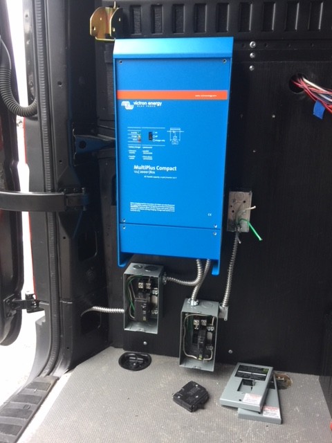
Looking at the operation manual. It appears when operating in "pass thru mode", Victron will still charge batteries & function normally but will pass thru a polarity mistake to the receptacles. When operating on its inverter output, the polarity at receptacles is correct.
Reverse polarity receptacles is fairly common. My experience about 8% receptacles I encounter are reversed. Further, on older 2 wire systems, about 15% some Dickhead Shadetree replaced old receptacle with a modern 5-15/20R & connected its groundpin to neutral. Even encounter hot groundpins on occasion...