You are using an out of date browser. It may not display this or other websites correctly.
You should upgrade or use an alternative browser.
You should upgrade or use an alternative browser.
Los Angeles -Class Attack Sub(urban), Build / Collected Werks topic - '02 k1500 Z71
- Thread starter rayra
- Start date
Overlandtowater
Well-known member
Are you going to store it in the back? You could bolt a piece of 2.5" tubing in the rear to keep it from moving around and killing someone inside if you were in an accident.
rayra
Expedition Leader
Nope I'm leaving the winch assemblage at home 99.9% of the time. If I'm heading off road it will get mounted to the front or rear hitch. Front hitch is 'out for delivery' today.
and of course, now my fuel pump appears to be keening its death song. Just made a 60mi round trip for a med appt and a bit of shopping and heard that high pitch keening sound while sitting at a light on the way home. That's what I get for spending $3-400 on winch related crap.
So now it's a race which craps out first, alternator or fuel pump.
/automotive trouble smells available money
rayra
Expedition Leader
yeah, I've got a couple 9500-lb-rated D-shackles, a 30' 30,000#-rated recovery strap, a 6' similar rated tree strap. And I'll have the 65' steel cable off the winch as an extension (but I'm going to have to put a loop and clamps on the winch end of that cable to turn it into an extension. Last thing to get is a snatch block or two and a suitable bag to tuck it all in. It's all loose in a drawer in the Sub, right now, all being useful gear even without a winch present.Rayra, I just use a heavy Shackle for my hook. I have found it very useful. I have run a couple of different types of hooks over the years but I keep going back to a simple shackle
rayra
Expedition Leader
Got the CURT front hitch via UPS this afternoon. Farted around with it a big, thinking to at least get teh end plates in. but the install calls for fishing a bolt and plate into the frame end for a rearward hole and putting another bolt thru a front hole which is currently occupied by tow hooks. So I have to take more things apart in order to do the install and pretty much ran out of time today.
We're heading over the Grapevine tomorrow to Buttonwillow racetrack, spectating an acquaintance's car club track day. I kinda wanted to install the front hitch and use our bike carrier and take our bikes up there with us, to get around the track infield more easily, taking pictures. Could still use the back hitch for same. But worried about the fuel pump now so not taking the Sub.
So I'll probably install it some time over the next week.
It's a heavy well-made piece of steel and came well packaged. Beautiful finish on it too. Grade 8 hardware.


rayra
Expedition Leader
CURT front hitch mount mounted.
Winch carrier fitted and successfully pinned / mounted. Took every fractional bit of slack in the front hitch bolt holes for the carrier to be pinned. Carrier handles hard up against the bumper. Probably won't be able to mount the winch in it due to curve / intrusion of the bumper.
I either need to get a shot hitch extension; have the carrier hitch tube welded / extended; or drill a new pin hole in the CURT about an inch closer to the opening. I'll wait until I have the winch mounted to the carrier before I make any mods.
The front hitch and carrier put together as exemplar

I've flipped the center portion of the front receiver so the tube is above the crossbar rather than under. Effectively raising the hitch ~4"+. In doing this the whole front hitch is out of sight behind the bumper trim / soft plastic skirt, instead of hanging down.


The CURT front hitch is very well done, it fit perfectly. Its end plates touch the bottom lip of the skirt, maybe protrude forward about 1/8" too much, unnoticeable from in front of the vehicle. The receiver tube itself even in the flipped position doesn't not interfere with either the plastic chin plate OR the bumper skirt. The receiver opening hovers about 1.25" behind the skirt.


When I cut the hole in the skirt I took a good look at where the receiver was lined up on the inside and then used a 1.25" hole saw on where I thought the center was. Then eyeballed thru that hole to create the 2"+ square cutout. The plastic skirt cut easily with a carpet knife BE CAREFUL. It took a couple trimmings to get a hole that lined up very well with the receiver.
Then I discovered I needed to enlarge the bottom of the hole to accept the bracing welded on the carrier. So the finished hole is sort of an ugly keyhole sort of thing and not just a clean square. With a little forethough I might have just drilled a large circular hole, would have been prettier.
The installation instructions / bolts for the front hitch are aimed at two existing holes in each of the frame ends. But on my Z71 the front hole is occupied by the factory tow hooks. Part of the install kit is a piece of spring wire used to fish the grade 8 carriage bolts and steel plates into the frame ends and guide the bolt down thru the frame hole. I dismounted my tow hooks to make this easier, got these rearward bolts inserted. Then put my hooks back in and used the bottom bolt that helps retain the hooks to also bolt down the CURT mounting plates.
Left the endplate mounting bolts loose. Then I held the crossbar up and dropped some end bolts in and got it secured to the end plates.
When it came time to insert the carrier, it went all the way in with the carrier handles hard up against the steel of the bumper. Couldn't quite get the pin in. I loosed up all the CURT bolts and shoved everything as far forward as the bolt holes would allow and got the pin in. Then tightened up all the bolts again, while shoving everything forward. Was able to move the pin out and in readily. But that just isn't going to be good enough.
Here's how tight the carrier fit is to the bumper. I expect it is going to interfere with mounting a winch. I know it will interfere with fitting a fabric cover to the whole thing.


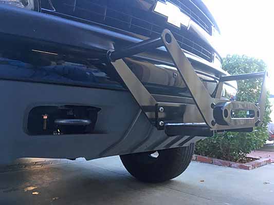
So I need to either extend the tube on the carrier. Or move the hole in the CURT receiver. There's a lot of material foward of the pin. I could move the hole an inch forward. And thus gain that 1" between carrier and bumper. But I'll wait for the winch to see how much room I really need.
I know they make hitch / receiver extension tubes. And might ultimate use such. Don't know yet.
Winch carrier fitted and successfully pinned / mounted. Took every fractional bit of slack in the front hitch bolt holes for the carrier to be pinned. Carrier handles hard up against the bumper. Probably won't be able to mount the winch in it due to curve / intrusion of the bumper.
I either need to get a shot hitch extension; have the carrier hitch tube welded / extended; or drill a new pin hole in the CURT about an inch closer to the opening. I'll wait until I have the winch mounted to the carrier before I make any mods.
The front hitch and carrier put together as exemplar

I've flipped the center portion of the front receiver so the tube is above the crossbar rather than under. Effectively raising the hitch ~4"+. In doing this the whole front hitch is out of sight behind the bumper trim / soft plastic skirt, instead of hanging down.


The CURT front hitch is very well done, it fit perfectly. Its end plates touch the bottom lip of the skirt, maybe protrude forward about 1/8" too much, unnoticeable from in front of the vehicle. The receiver tube itself even in the flipped position doesn't not interfere with either the plastic chin plate OR the bumper skirt. The receiver opening hovers about 1.25" behind the skirt.


When I cut the hole in the skirt I took a good look at where the receiver was lined up on the inside and then used a 1.25" hole saw on where I thought the center was. Then eyeballed thru that hole to create the 2"+ square cutout. The plastic skirt cut easily with a carpet knife BE CAREFUL. It took a couple trimmings to get a hole that lined up very well with the receiver.
Then I discovered I needed to enlarge the bottom of the hole to accept the bracing welded on the carrier. So the finished hole is sort of an ugly keyhole sort of thing and not just a clean square. With a little forethough I might have just drilled a large circular hole, would have been prettier.
The installation instructions / bolts for the front hitch are aimed at two existing holes in each of the frame ends. But on my Z71 the front hole is occupied by the factory tow hooks. Part of the install kit is a piece of spring wire used to fish the grade 8 carriage bolts and steel plates into the frame ends and guide the bolt down thru the frame hole. I dismounted my tow hooks to make this easier, got these rearward bolts inserted. Then put my hooks back in and used the bottom bolt that helps retain the hooks to also bolt down the CURT mounting plates.
Left the endplate mounting bolts loose. Then I held the crossbar up and dropped some end bolts in and got it secured to the end plates.
When it came time to insert the carrier, it went all the way in with the carrier handles hard up against the steel of the bumper. Couldn't quite get the pin in. I loosed up all the CURT bolts and shoved everything as far forward as the bolt holes would allow and got the pin in. Then tightened up all the bolts again, while shoving everything forward. Was able to move the pin out and in readily. But that just isn't going to be good enough.
Here's how tight the carrier fit is to the bumper. I expect it is going to interfere with mounting a winch. I know it will interfere with fitting a fabric cover to the whole thing.


So I need to either extend the tube on the carrier. Or move the hole in the CURT receiver. There's a lot of material foward of the pin. I could move the hole an inch forward. And thus gain that 1" between carrier and bumper. But I'll wait for the winch to see how much room I really need.
I know they make hitch / receiver extension tubes. And might ultimate use such. Don't know yet.
rayra
Expedition Leader
So I think I've figured how I'm going to solve the too-tight fit of the carrier. I looked at hitch extensions, but they are too long, 7-8" being the shortest. Then I though about having a new receiver mouth welded on to the CURT front hitch. But really didn't want to rely on such a weld in such a place. So then I started considering altering the winch carrier's receiver tube. That can get a welded extension of about 4" and have a smaller size tube put inside both the old and new tubes and have it welded in several places and even thru-bolted thru the original tube. And then have the new pin hole drilled thru both nested new pieces and it should be as strong as the original tube and possibly even stronger.
I really only need about 2-3" of added length / pin relocation to get the bumper clearance i want. But I'll wait until I have the actual winch setup to verify that before seeking to have the modification done.
And it's pretty much just chance that I was able to get it pinned as is. The tight fit hard against the bumper has to just be an accident. The carrier handles have already chewed the paint up a bit.
A rough sketch of the idea.

rayra
Expedition Leader
messing with winch wiring connection ideas.
when I routed the 1/0 cabling into the cargo area, to the 'power module', I came up thru the cargo floor and used a pair of bulkhead fittings typically used for junction boxes. THey make a waterproofed connection with the flex conduit I ran the cable thru.
I experimented with a couple layouts with the future winch cabling in mind.
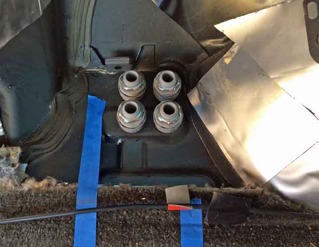
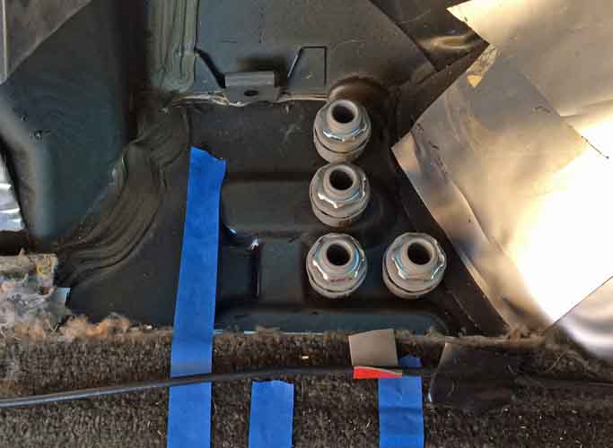
I basically went with the rightmost pair of the 1st image. The crease in teh carpet at the bottom of both panels is where the cargo area sidewall panel rests. All this area is behind the panel.
I cut down the factory subwoofer box to make room for the cabling
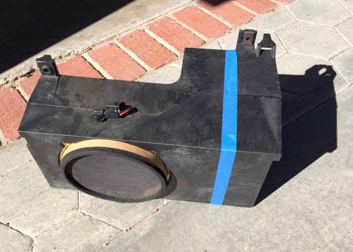
I left just enough room for the future pair of bulkhead fittings between the first pair and the box.
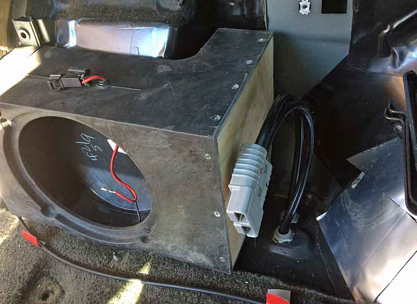
The main cabling thus comes up thru the floor, the coupler is bolted to the box and there's a hole thru the cargo sidewall and 'power module' box, where the mating coupler and wiring feeds the various inverters, rotary cutoff that for now ust controls main power to the 1000W inverter, and with some terminal studs where other power feeds and grounds attach for the fuse panel, other inverters, the solar charger etc.
The power going to the rear bumper will spawn inside that power module from those couplers and that rotary switch, and pass thru another mating pair of connectors at the cargo wall and down thru the floor and to the plug at the back bumper. That's complicated, but it puts the cutoff for the rear bumper plug inside the vehicle.
There's be two stacked plugs where there is one now -
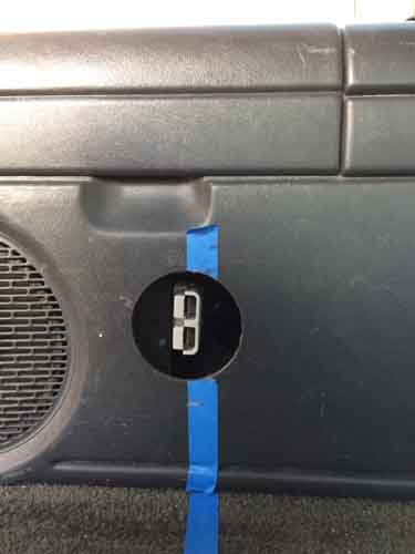
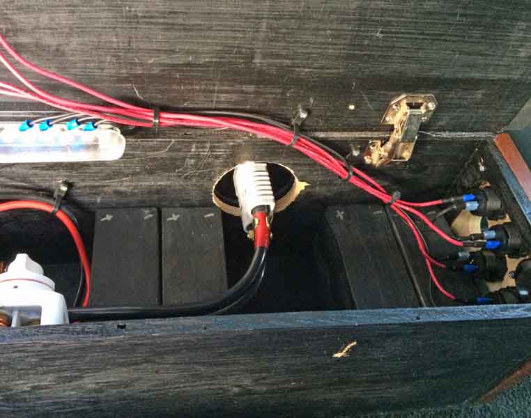
The rotary cutoff switches are 3" tall / deep. Take a lot of room. Right now I have no idea where I'm fitting the front one under the hood, close to the positive terminal of the aux batter. Battery, overflow / fill tank, air box, it's a crowded area with no room above, either. And the AC plumbing and fill port is right alongside the Aux battery. I will probably move my battery combiner solenoid more towards the centerline and fit the rotary switch where the solenoid is now. But that's other wiring routing issues. need to stare at it or some pictures for a while and suss it out.
Another complication, that subwoofer and box are probably coming out. I'll need a bracket to position the stacked plugs. I'm long-range shopping a larger air compressor / tire inflator to go into that volume. And probably be hard plumbed to an air tool coupling also on the rear bumper.
looking at this compressor -
The shipping box dimensions are 6x6x10, so it ought to fit in that subwoofer space.
I can wire it up thru the cargo wall hole into the power box fuse panel, and put a switch on the back panel of the power box. Just flip a switch and jack in an air line to fill tires or inflate whatever. Or blow sand off something. Or blow out an air filter. :winking:
I need to fish around for compressor recommendations and real sizings.
when I routed the 1/0 cabling into the cargo area, to the 'power module', I came up thru the cargo floor and used a pair of bulkhead fittings typically used for junction boxes. THey make a waterproofed connection with the flex conduit I ran the cable thru.
I experimented with a couple layouts with the future winch cabling in mind.


I basically went with the rightmost pair of the 1st image. The crease in teh carpet at the bottom of both panels is where the cargo area sidewall panel rests. All this area is behind the panel.
I cut down the factory subwoofer box to make room for the cabling

I left just enough room for the future pair of bulkhead fittings between the first pair and the box.

The main cabling thus comes up thru the floor, the coupler is bolted to the box and there's a hole thru the cargo sidewall and 'power module' box, where the mating coupler and wiring feeds the various inverters, rotary cutoff that for now ust controls main power to the 1000W inverter, and with some terminal studs where other power feeds and grounds attach for the fuse panel, other inverters, the solar charger etc.
The power going to the rear bumper will spawn inside that power module from those couplers and that rotary switch, and pass thru another mating pair of connectors at the cargo wall and down thru the floor and to the plug at the back bumper. That's complicated, but it puts the cutoff for the rear bumper plug inside the vehicle.
There's be two stacked plugs where there is one now -


The rotary cutoff switches are 3" tall / deep. Take a lot of room. Right now I have no idea where I'm fitting the front one under the hood, close to the positive terminal of the aux batter. Battery, overflow / fill tank, air box, it's a crowded area with no room above, either. And the AC plumbing and fill port is right alongside the Aux battery. I will probably move my battery combiner solenoid more towards the centerline and fit the rotary switch where the solenoid is now. But that's other wiring routing issues. need to stare at it or some pictures for a while and suss it out.
Another complication, that subwoofer and box are probably coming out. I'll need a bracket to position the stacked plugs. I'm long-range shopping a larger air compressor / tire inflator to go into that volume. And probably be hard plumbed to an air tool coupling also on the rear bumper.
looking at this compressor -
Amazon.com: Viair 00088 88P Portable Air Compressor: Automotive
Buy Viair 00088 88P Portable Air Compressor: Air Compressors & Inflators - Amazon.com ✓ FREE DELIVERY possible on eligible purchases
smile.amazon.com
The shipping box dimensions are 6x6x10, so it ought to fit in that subwoofer space.
I can wire it up thru the cargo wall hole into the power box fuse panel, and put a switch on the back panel of the power box. Just flip a switch and jack in an air line to fill tires or inflate whatever. Or blow sand off something. Or blow out an air filter. :winking:
I need to fish around for compressor recommendations and real sizings.
rayra
Expedition Leader
Needing to change my alternator, thinking about an aftermarket 253A, rather than 'merely' going from factory 130A to factory option 145A. But that much potential alternator output calls for a much thicker charge wire from the alternator to the battery cable junction terminal, that red box above the power steering cap, where we're SUPPOSED to attach the (+) jumper cable.
Haven't found a definitive online article yet, just some general hot rodding discussions on it. I'm sure there's also a lot of good stuff and pre-fabbed wires in the competition car audio forums, have to look some more.
going down the rabbit hole of needing to upsize the charge wire from my higher-output alternator to the battery terminal / jumper cable connection block above the power steering, that nobody bothers to use. The factory wire isn't sized to handle the full output of the higher output alternator. And maybe that's why I need to put a dash switch on the keyed solenoid-triggering wire. So I can manually switch off the solenoid and winch solely off my Aux battery while still running the vehicle and trying to get unstuck. No fear of a max pull then frying the solenoid or my alternator charge wire. And that's a reminder to have a spare charge wire once the winch is operational.
Looking at 2AWG and maybe even a 1AWG bit of welding cable. more later. High output alternator isn't purchased yet.
/
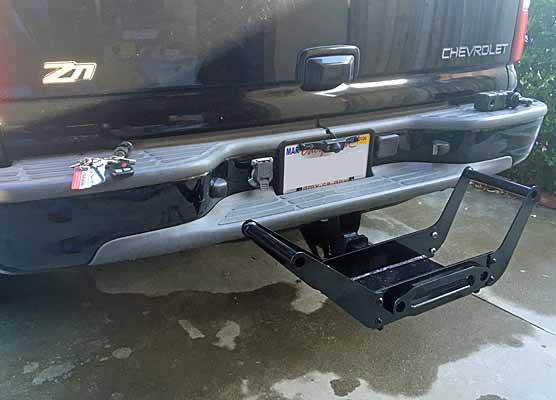
Was farting around with the carrier some more, preparing to cut the hole in the rear bumper for the power plug. Pretty sure I need to get 3-4" added to the 2" OD tail on the carrier. Need it for clearance up front. Not so much in the rear. But here's a couple shots of the carrier mounted in the rear. The power plug will be left of the relocated 7-pin, left of the plate.


rayra
Expedition Leader
Alrighty, phat 253Amp alternator ordered. should be installing it in a week.
shopping around online for a fat charging wire to use with it. Can't find any info on the new ALT about a thicker wire needed or provided. But it's a sure thing the factory 4ga wire from alternator to battery cable connection is in no way sufficient at the full charge rate. First time I try to do a hard winch pull with the engine running, that charge wire would probably smoke.
Lots of hints at thicker wires on competition car stereo forums, and some available off amazon (non-prime) for not terrible markups. I can make a cable easily and probably will. I have to buy a bunch of 1/0 welding cable to complete the winch plugs anyway and the alternator charge wire is 10-12". And ought to be the same large gauge. I'll basically have the whole electrical run from ALT to Winch wired and fused to accommodate at least 200A.
rayra
Expedition Leader
The saddle clamps are here! The saddle clamps are here!

The U-shaped thing is called a thimble. Supports and forms the loop in a cable end. You wrap the 'dead' end of a cable around it, back along the 'live' side of the cable (the rest of it). The live end lays in the saddle, the dead end on top of it, the U-bolt pinching down on top of the dead end. There's formulae for length vs diameter of the cable etc and whether you use 2 or 3 saddles.
I'm going to use these on the 65' of 3/8" steel cable that comes with the winch, turning the dead end that screws to the winch drum into this loop. And keeping the loop and hook on the other end. This will become either an extension to my synthetic winch line, or used to rig snatch blocks. Could even be used as a tow cable.
Once the loop is assembled I'll wrap everything up in a bunch of 1" gaffer tape, or some similar cloth-backed tape. Bind it all up for easy snag-free handling.
rayra
Expedition Leader
Started hacking a hole in my rear bumper face for the rear winch plug. Figuring out the bracket needed to float the plug where I want it in the hole, so the weather boot will fit into and partly fill the hole. Will finish cutting and dressing the hole tomorrow. It's an ugly mess right now, was running out of daylight. The second pic is the back side of the bumper in that area. I previously cut in and relocated my 7-pin trailer connector to the area.


In the future I might hard-plumb an onboard compressor air coupling on the other side of the bumper step, outboard of the spare tire winch cover.


In the future I might hard-plumb an onboard compressor air coupling on the other side of the bumper step, outboard of the spare tire winch cover.
rayra
Expedition Leader
The real PITA is the wiring / cabling changes needed for the front plug extension and the adding of an inline circuit breaker / thermal fuse and a rotary cutoff switch for the front plug. I've got too much going on with the Aux battery and no room to do it all in.

When I first went with an Aux battery in the factory under-hood location, I added a 200A combiner / isolator solenoid, which is controlled by a keyed power source. Got a phat 1/0 cable added to the (+) post on my starting battery, up along the top of the firewall / coaming to the solenoid and then a short section of the same cable from the solenoid to the (+) on the Aux battery. Been like that for 3yrs+. Works fine.
But now I need to add an additional 1/0 cable to both terminals of the Aux, to feed the front plug. And I'll be adding a 150-200A circuit breaker at the battery terminal. The 1/0 cable that runs to the back of the vehicle will get connected to the other end of the breaker / fuse. So will the new line for the front plug. And THAT line will go right to a rotary switch so the front plug can be dead when not in use. The rear plug will be likewise interrupted by a rotary switch already in my rear power module. The rear plug extension will extend from that module.
Problem is I've got no convenient room for all this. The only open space is south, on the plastic wheel tub, or on some sort of shelf I fabricate to extend out from the bottom of the Aux battery (between it and its tray). The vehicle AC lines and ports are right in the way.
So I have to think about that. I would probably use a slab of UHDPE as a shelf/ breadboard to mount things to. And it would keep the rotary switch accessible.
I originally fashioned the Aux ground cable from that stiff THNN cable I had a lot of, that was a mistake as it was very difficult to work it into place. That needs to be re-done and tucked between the AC lines and the Aux.
I also need a different sort of terminal attachment for my side-terminal battery that will let me bolt more stuff to each terminal.
Looking around today and taking pictures it seems I'm going to have to re-do a few things -
a.) properly source the Aux feed cable from the little red junction box where the Alternator charge wire connects to the fat cable running from starting battery to starter.
b.) relocate the combiner solenoid to the face of the big fuse block on the driver side. Then run its big 1/0 cable the same route it is now, to the (+) on the Aux.
c.) I can then also mount my Aux fuse panel in the same area as the solenoid, more convenient to run my radio power lines etc thru the firewall from there, anyway.
d.) That gets most the stuff out of the way by the Aux battery and I can mount the rotary cutoff for the front plug where the solenoid is right now. Up high and mostly dry.
e.) find better terminal connects for the side post battery that will let me better stack the three 1/0 cables that have to hang from each terminal


and by way of explanation
1 - negative 1/0 going to rear of vehicle
2 - ground to frame that needs to be replaced
3 - positive 1/0 going to the rear, connected to a rotary cutoff right now. No fusing, always hot. Goes to the back power module, inverters, and is backfed by my rooftop solar.
4 - top of the PAC solenoid on the firewall. That needs to be swapped over to the driver side
5 - mess. A rotary cutoff. A small fuse block that mounts right to the terminal bolt. That's all got to change. And it all blocks the AC port.
thin yellow line - follows the stiff ground cable down to the frame rail. All that needs to go behind the aluminum AC lines. with relocation of the solenoid and better placement of the new rotary cutoff, there'll be more room for a better terminal connection and the cables can hang down and behind the AC stuff.


When I first went with an Aux battery in the factory under-hood location, I added a 200A combiner / isolator solenoid, which is controlled by a keyed power source. Got a phat 1/0 cable added to the (+) post on my starting battery, up along the top of the firewall / coaming to the solenoid and then a short section of the same cable from the solenoid to the (+) on the Aux battery. Been like that for 3yrs+. Works fine.
But now I need to add an additional 1/0 cable to both terminals of the Aux, to feed the front plug. And I'll be adding a 150-200A circuit breaker at the battery terminal. The 1/0 cable that runs to the back of the vehicle will get connected to the other end of the breaker / fuse. So will the new line for the front plug. And THAT line will go right to a rotary switch so the front plug can be dead when not in use. The rear plug will be likewise interrupted by a rotary switch already in my rear power module. The rear plug extension will extend from that module.
Problem is I've got no convenient room for all this. The only open space is south, on the plastic wheel tub, or on some sort of shelf I fabricate to extend out from the bottom of the Aux battery (between it and its tray). The vehicle AC lines and ports are right in the way.
So I have to think about that. I would probably use a slab of UHDPE as a shelf/ breadboard to mount things to. And it would keep the rotary switch accessible.
I originally fashioned the Aux ground cable from that stiff THNN cable I had a lot of, that was a mistake as it was very difficult to work it into place. That needs to be re-done and tucked between the AC lines and the Aux.
I also need a different sort of terminal attachment for my side-terminal battery that will let me bolt more stuff to each terminal.
Looking around today and taking pictures it seems I'm going to have to re-do a few things -
a.) properly source the Aux feed cable from the little red junction box where the Alternator charge wire connects to the fat cable running from starting battery to starter.
b.) relocate the combiner solenoid to the face of the big fuse block on the driver side. Then run its big 1/0 cable the same route it is now, to the (+) on the Aux.
c.) I can then also mount my Aux fuse panel in the same area as the solenoid, more convenient to run my radio power lines etc thru the firewall from there, anyway.
d.) That gets most the stuff out of the way by the Aux battery and I can mount the rotary cutoff for the front plug where the solenoid is right now. Up high and mostly dry.
e.) find better terminal connects for the side post battery that will let me better stack the three 1/0 cables that have to hang from each terminal


and by way of explanation
1 - negative 1/0 going to rear of vehicle
2 - ground to frame that needs to be replaced
3 - positive 1/0 going to the rear, connected to a rotary cutoff right now. No fusing, always hot. Goes to the back power module, inverters, and is backfed by my rooftop solar.
4 - top of the PAC solenoid on the firewall. That needs to be swapped over to the driver side
5 - mess. A rotary cutoff. A small fuse block that mounts right to the terminal bolt. That's all got to change. And it all blocks the AC port.
thin yellow line - follows the stiff ground cable down to the frame rail. All that needs to go behind the aluminum AC lines. with relocation of the solenoid and better placement of the new rotary cutoff, there'll be more room for a better terminal connection and the cables can hang down and behind the AC stuff.

rayra
Expedition Leader
Last thing I messed with today was examining the alternator charge wire arrangement and sizing, length, terminal sizings.
The factory wire is 'just enough' for the offered amperage options, which top off at 145A. Since I just bought a much higher output alternator, this power wire needs to be upgraded. Big is Good. So I'm changing it to 1/0 too.
I can build it myself, I've built and am building the other big cables and am buying a bunch of welding cable to finish the winch plugs at both ends of the vehicle, so an 11" ALT charge wire is no problem. But they can be had pre-made pretty reasonably -
so I'm probably ordering it. It will get here a few days after the ALT does. And I won't ever need its extra capability until I'm winching something hard with the engine running / key on. So I could just leave the factory wire on until after I have the winch.


That terminal lug inside the red box where the ALT charge wire connects is where I should have run the Aux cabling from, anyway. And where it will be re-run from.
The factory wire is 'just enough' for the offered amperage options, which top off at 145A. Since I just bought a much higher output alternator, this power wire needs to be upgraded. Big is Good. So I'm changing it to 1/0 too.
I can build it myself, I've built and am building the other big cables and am buying a bunch of welding cable to finish the winch plugs at both ends of the vehicle, so an 11" ALT charge wire is no problem. But they can be had pre-made pretty reasonably -
so I'm probably ordering it. It will get here a few days after the ALT does. And I won't ever need its extra capability until I'm winching something hard with the engine running / key on. So I could just leave the factory wire on until after I have the winch.


That terminal lug inside the red box where the ALT charge wire connects is where I should have run the Aux cabling from, anyway. And where it will be re-run from.
rayra
Expedition Leader
Got the rear bumper hole cut in and cut edges painted, yesterday. Here's a pic with the plug and its large black weather boot positioned in the hole. The plug end will be positioned about 1/2" proud of the bumper sheet metal, the weather boot slides onto the plug, into the hole, in just about this position pictured. The rounded outer edge of the boot basically covers the hole.

I'm going to fashion an angled mounting bracket for the plug out of a 2" wide strip of plate steel. The strip will have about a 45deg bend in the middle and will be bolted to the bumper between the plug location and the license plate light fixture to the left, on the angled part of the bumper. with the other end of the strip thus positioned perpendicular to the bumper face at the plug hole. The plugs have two thru-holes for bolting them down to anything. To the strip in this case. This will all be positioned so the plug mouth is floating centered in the cut opening in the bumper. And the strip will be thick enough to resist any bending from working with these heavy plugs.
I just have to figure out how I'm bending that strip without hammering my vises off their bench mounts. Maybe I jack up one front corner of the Sub and position the steel strip over a piece of black iron pipe, like a see-saw, under the front tire and lower the vehicle onto it. That ought to put a nice bend in it. Hope to get that fashioned over the next couple days.
Then it's on to cutting the grill for the front plug and getting that mounting bracket figured out. It might get attached to the passenger-side mounting brackets of my transmission cooler.
Similar threads
- Replies
- 44
- Views
- 8K
