Lowly the Lorry. . .

Lowly Update:

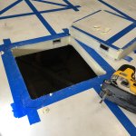
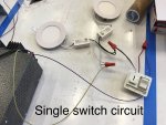
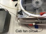
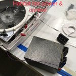
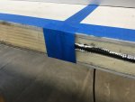
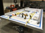
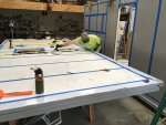
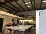
Electrical wiring installation is currently underway on the yet-to-be installed habitat lid panel.

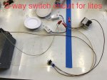
I'm testing and documenting the various circuit types before I install them to limit the headaches I will encounter once I seal up the lid's edges and lower the lid onto the habitat's walls. A buddy has loaned me a 12V power supply to conduct the testing and so far I haven't created any blue smoke!
IMG_7659.jpg
IMG_7661.jpg
IMG_7662.jpg
IMG_7663.jpg
IMG_7838.jpg

- Sheik
 
Last edited:
Lowly Update:

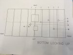
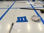
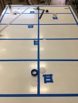
Once I established what wires needed to go where for each type of circuit, I laid out the placement of the pockets I would be cutting on the underside of the lid panel for the LED can lights:
IMG_7740.jpg
IMG_7738.JPG
IMG_7739.JPG

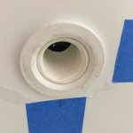
I used a 1" spade bit to pilot drill thru the fiber-reinforced-plastic (FRP) interior shell before using my router to hog out the rest of the can light pocket. Glad I have a good shop vacuum because this created a massive amount of FRP, Azdel and foam dust!
IMG_7741.jpg
IMG_7742.JPG
IMG_7743.JPG

I then used a series of feeler bits to drill through the foam between the can light pocket and the rectangular side-side tubes that are every 24" on-center on every Globe Trekker habitat panel:
IMG_7744.JPG
IMG_7745.JPG

In hindsight, I should have located my can lights as close to the rectangular tubes as possible to limit the extra work and frustration of searching for and drilling through these aluminum tubes at shallow angles. The can light located in the bathroom was half way between two of these tubes and resulted in much gnashing of teeth.

Once the can light pockets were established with their feeder holes into the aluminum cross tubes I used a frayed construction string and my shop vacuum to suck the string through the passage and create a wire snake. Once the snake was through I was able to tape on the appropriate wires and pull them through.
IMG_7746.JPG

- Sheik
 
Last edited:
Lowly Update:

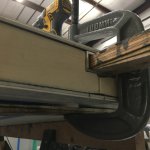
There is a need to collect all of the wiring going in/through the lid panel and deliver it to one specific place within the habitat that will serve as the electrical distribution center. This will require a pass-through from the side-side aluminum rectangular tube directly above this space in order to provide strain relief and protect the wires from rubbing on a sharp corner; think of it as a large grommet. I could have 3D printed one but figured I could just as cheaply and quickly fabricate one out of 3/4 SCH40 PVC pipe and fittings.

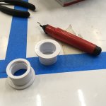
I first located the hole's position and used a 1 3/8" spade bit to cut through the FRP skin, underlying Azdel layer, foam insulation and bottom wall of the rectangular tube. The spade bit took awhile to make cut its way through the aluminum but it did manage. Next was using a de-burring tool to "soften" the inside edge of the two PVC reducers:
IMG_7844.JPG

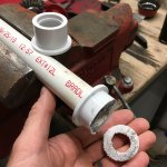
The Dewalt port-a-bandsaw was then tasked with cutting the reducers down in length to remove the internal bore's step and create a consistent sized through bore and make one short enough to fit into the aluminum tube:
IMG_7845.JPG

3/4 SCH40 PVC pipe was cut to the appropriate length and all the parts were cleaned up in preparation for assembly:
IMG_7846.JPG

A bit of white silicone caulking, PVC glue and judicious clamping ensued:
IMG_7847.JPG

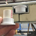
The finished product turned out pretty nice and allows for adequate passage of the wiring headed into the lid panel and beyond. Cheap as chips and functional; what more could a guy ask for?
IMG_7857.JPG

- Sheik
 
Last edited:
Lowly Update:

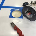
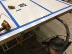
Before I could finish running electrical in the lid of the habitat I needed to cut the holes for the fan and skylight. Wiring needed to get to both these voids along with a can light that used the same access tube. I first laid out painters tape in the approximate areas of the cutouts, marked and triple checked not only the required size of the cutouts but the layouts I had drawn on the top of the lid. Not trusting my ability to draw the same round-cornered box at the same location on both sides of the lid panel I devised a plan to use a 3D printed drill guide along with a 3/16" feeler bit to drill holes at the center points of the radiused corners.
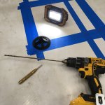
IMG_8014.JPG

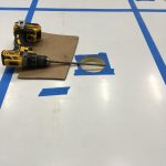
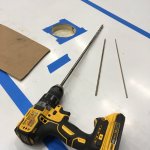
Once all 4 holes were drilled through the panel, perpendicular to the plane of the panel I made a cardboard template of the cutout hole with 3/16" holes in the same location as the holes just drilled in the panel. Using 3/16" drill bits to serve as pins, I pushed the "pins through the panel holes until they protruded through both sides of the panel. I then was able to climb underneath the panel (which is up on saw horses), slip the cardboard template over the pins and trace its outline onto the bottom of the panel. With the pins were perpendicular to the panel I knew with some certainty the layout on the bottom of the panel now matched the size and location as its corresponding layout on the top side.
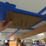
IMG_8018.JPG

Using a circle cutter centered on the 3/16" radius center holes, I then cut through the panel's skin on the top and then from below.
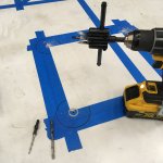
IMG_8015.JPG

With the "coins" removed from the corners of both the top and bottom of the cutout, I was then able to pass a long jigsaw blade through the remaining foam and start cutting the sides of the cutouts quite easily.
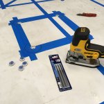
IMG_8016.JPG
IMG_8021.JPG

****WARNING****: Jigsaws are evil! When trying to cut even a straight line through a thick panel the blade will begin to flex sideways resulting in a cutout that will result in elevated blood pressure and gnashing of teeth. Stay away from jigsaws!

After inferior results using the jigsaw to make the entire cut, I switched over to a vibrating tool with much better results, but requiring cuts on both sides of the panel. Foam between the cuts was sliced using a long bladed razor while the jigsaw was reluctantly used for cutting the aluminum tubing.
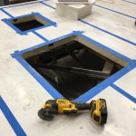
IMG_8023.JPG

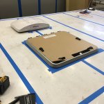
With both holes cut, the moment of truth had arrived: would the fan and skylight actually fit into the holes. Drum roll please. . .
IMG_8025.JPG

Thankfully the mounting flanges will hide the screwups made by the jigsaw and everything will look like it was done by a professional - ha! Glad to have these cutouts behind me so the lid wiring can get finished up. I'll definitely continue to employ the drill guide/pin/template/layout technique but avoid the using the jigsaw on long cuts like hemorrhagic fever.

- Sheik
 
Last edited:
Lowly Update:

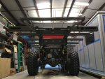
Finally got the truck running again (dead battery) to get it down to the scales and measure its weight. Wanted to document how much of a diet Lowly has been on since I purchased him.

Here's what he looked like off the boat from Wales and how much he weighed (in kg) on our drive across Canada:
IMG_1993.jpg
IMG_2063.JPG

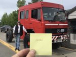
Here's what he looks like now along with how much he weighs (in lbs):
IMG_8066.jpg

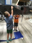
Note: I haven't aged 30 years since purchasing the truck; my dad decided to pose for the pic and my boys are playing the part of Goldbug (another reference to Richard Scarry's wonderful automotive kids books)

For those of you who can't do metric to english conversions in your head, here are the numbers:
ORIGINAL WEIGHT - 8340 kg, 18387 lbs
STRIPPED DOWN WEIGHT - 5498 kg, 12120 lbs
DIFFERENCE OF - 2842 kg, 6267 lbs

Holy mackerel, Kingfish! I've removed over 2.8 tons of weight from Lowly; just think of the improved fuel economy! Alas, now the weight must start going back on. . .

- Sheik
 
Last edited:

RoamIt

Well-known member
That's interesting, I was also going to do an before and after weight, but didn't think of a stripped down weight metric. That would quantify exactly how much my fully kitted box weighs.
'Ranger' (working name of rig) weighs 18,612lbs or 8460kg for my more advanced friends.
 
Lowly Update:

Progress continues at a snail's pace due to summer commitments sitting on various inflatable watercraft and rowing said vessels down whitewater laden rivers until my shoulders and elbows protest in agony. While it is a passion of mine and a pleasure to get paid doing it, I've spent many hours floating down rivers contemplating the neglect Lowly has endured. With the end of the rafting season in sight, progress on the lorry will hopefully pick up.

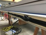
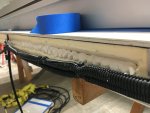
All wiring for circuits imbedded into the ceiling and walls (fixtures, switches and wiring that can't be run through cabinetry) has been run in the lid panel and tested for proper continuity. The last thing to do before installing the lid's perimeter aluminum extrusions is to embed the wiring into the edge of the panel to eliminate any interference between the extrusion and the wiring. RV Globe Trekker's extrusions do come with recesses specifically for running wiring, but to minimize frustration (and based on their recommendation) I went ahead and carved a trough in the panel's foam edge large enough to accommodate the armored wire looms:
IMG_8311.JPG

Next, a bead of cheap caulking was laid down in the bottom of the trough to serve as adhesive for the wire loom:
IMG_8312 2.JPG

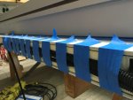
I then used painter's tape to hold the wiring loom into the trough while the caulking cured:
IMG_8313 2.JPG

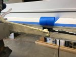
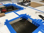
In a couple places the wiring had to transverse around the cutouts in the lid and needed to be recessed in those areas as well:
IMG_8314.JPG

With the caulk cured, the tape could be removed. This "glue" is only meant to hold until the aluminum extrusions are installed; it is fine if the wiring looms release into the aluminum extrusion's wire chase voids once the habitat assembly is complete.
IMG_8316.JPG

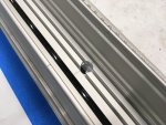
There are three places where wiring needed to pass from the lid panel into the rectangular extrusion stiffeners/wiring chases in the walls so switches could be cleanly installed in the wall panels. A 9/16" pass-thru hole was located and drilled into the habitat's upper corner extrusions for armored wire loom passage:
IMG_8315.JPG

- Sheik
 
Last edited:
Lowly Update:

The habitat's door and window cutouts were located using the same method of dimensional drawings, templates and thru-hole drilling used on the lid's skylight and vent cutouts. I then proceeded to cut out the door and back-left window as their removal was necessary for running wiring coming down through the lid's aluminum extrusions and for gaining entry into the habitat once the lid and back wall are installed. I primarily used the oscillating cutting tool with a diamond abrasive blade to cut through the panel's skin and then a long razor knife to cut the foam. This time the jigsaw was only employed to cut through the rectangular aluminum extrusions using the already cut skin as a guide for the jigsaw blade.

IMG_8335.JPG

Expanding foam was then used to fill the ends of the rectangular aluminum extrusions in the edge of the lid. Painters tape was used to limit how much foam exited the tubing as it expanded and to limit necessary cleanup.
IMG_8330.JPG
IMG_8331.JPG

The front extruded edge was then installed on the lid panel and allowed to cure for 24 hours. So glad I was able to diagnose the excessive interference found when putting together the other panels and make the router jig to modify the remaining extrusions; it was orders of magnitude easier to install!
IMG_8329.JPG

Side extrusions were then installed on the lid. Again, so easy with just a slight interference fit that only ratchet straps were needed to get the extrusions to seat all the way home with the adhesive acting as both a lubricant and a brake (no dead-blow hammering necessary this time!).
IMG_8334.JPG

Once these 3 extrusions were given time to cure in place it was time to hoist the lid panel, roll the habitat underneath and lower the lid down onto wood blocking, directly above its future location. 3 cheers for macro visual progress!
IMG_8337.JPG
IMG_8338.JPG
IMG_8339.JPG

- Sheik
 
Last edited:
Lowly Update:

Back from a summer of raft guiding for long enough to prep and place the lid panel onto the habitat box. A two-man job made possible by reviewing the RV Globe Trekker how-to video, using a handful of ratchet straps, a couple of ladders and the Dewalt battery powered caulking gun.

IMG_8596.JPG
IMG_8597.JPG

Should have slid the rear panel's vertical extrusions into place with additional 1/8" spacers (dry, no glue) before lowering the lid to space the lid vertically while it cured in place. The vertical gap is now 1/8" tighter than the length of the vertical extrusions. Will have to get creative in how to get the rear panel with its extrusions into place.

Rear panel installation prep is underway - should have this thing cubed up in the next couple days!

- Sheik
 
Last edited:
Lowly Update:

Back panel is installed! Glad I was able to foresee the need for additional help on this one as it took 4 of us to position and coax/torture it into place. For those of you embarking on one of these DIY habitats, plan on using more adhesive than you think it will take!

IMG_8600.JPG

Wondering if it might be easier to put the lid on last (with the assist of gravity) rather than the back panel? A good feeling to have this thing finally glued together. The space gained in the shop by having all the panels and extrusions out of the way is glorious!

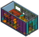
Real-world measurements of the habitat's interior volume can now be made and used in the computer model of the interior buildout. Most of the interior design is complete but want to verify measurements before finalizing cabinetry. A cubist's easter egg:

Screen Shot 2022-09-17 at 9.19.35 AM.png

I can now cutout out the remaining windows and hatch holes in the habitat as well as get the subframe ready to install on the truck's chassis (now that it has been given room enough to move out of the rear of the shop!)

- Sheik
 
Last edited:
Lowly Update:

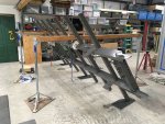
With the habitat box glued together, it was time to start assembling the parts onto the truck for the habitat to mount to. First order of operations was to fip the subframe right-side up. Once again ExPo member mog's jack lifts came in very handy. Hopefully this will be the last time I conduct this scary maneuver with this very heavy weldment!
IMG_8613.JPG

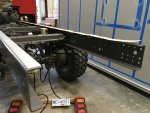
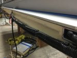
Next I prepped the top of the chassis rails for installation of sticky backed UHMW wear strips. These will help aid any movement between the subframe and chassis rather than have paint-paint or steel-steel contact:
IMG_8614.JPG
IMG_8661.JPG

The subframe was then lifted high enough for the truck to back underneath:
IMG_8662.JPG

The subframe was then lowered in place onto the chassis and shifted front/back to its final resting place. The side plates were then bolted to the chassis and the subframe match-drilled. A couple of shop helpers then bolted the side plates to the subframe:
IMG_8666.JPG
IMG_8671.JPG

The rear cross-member was then bolted in place along with the rear winch weldment:
IMG_8668.JPG

Rear winch components were then assembled onto the truck:
IMG_8674.JPG

Spring detent plungers were also installed in the end of each of the subframe's crossmembers for capturing yet-to-be-fabricated pull out deck joist sliders:
IMG_8681.JPG

Feels so good to be putting things back on the truck!

- Sheik
 
Last edited:
Lowly Update:

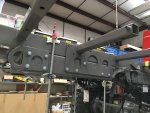
18,000 lb electric winch bolted up under the subframe. All 6 bolts lined up with no issues; time to go buy a lottery ticket.
IMG_8682.JPG

Now I've got to figure out how to wire this thing up to the truck's power supply and connect up Lowly's original winch control ports (both front and rear) to this new piece of kit. Have I mentioned that electrons are not my thing?

- Sheik
 
Last edited:
Lowly Update:

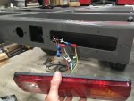
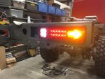
Took awhile sorting out what wire was for each particular function, especially since the taillights I source off Ebay didn't come with a wiring diagram! Trial and error won out in the end and we were able to get the new taillights wired, labeled and installed.
IMG_8692.JPG
IMG_8700.JPG

- Sheik
 
Last edited:

mog

Kodiak Buckaroo
Great minds think alike (from the 'I need to get these installed one-day collection') :rolleyes:
taillights.jpg
 

Forum statistics

Threads
188,342
Messages
2,905,814
Members
229,959
Latest member
bdpkauai

Members online

Top