Lowly the Lorry. . .

Lowly Update:

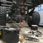
With the tail lighting mainly complete it was time to turn the attention to the winch's wiring. Keep in mind that the previous winch was hydraulically driven off of the truck's now removed PTO and this new Mile Marker winch is driven off of the truck's 24 volt power. Wiring for the winch control plug-ins and emergency stop buttons located at the front and rear of the truck had to be traced and sorted out in order to integrate them into the new winch's control wiring.
IMG_8703.JPG

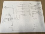
It was a spaghetti noodle mess for awhile but we finally managed to crack the nut and got the new winch to operate using the truck's power and the original controls. The E-stops even work as they should! I even managed to make a circuit sketch at the wiring box for posterity's sake.
IMG_8704.JPG

Big thanks to a shop here in Grants Pass, Oregon called Alternative Power & Machine. Its one of those hole-in-the-wall shops that has everything needed for wiring up power throughout a truck such as mine; the sort of shop where the employees actually know more about their product than you do. Great resource!

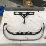
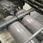
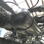
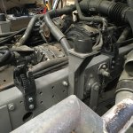
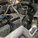
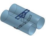
I'm now going through all of the truck's systems located between the chassis rails and underneath the soon-to-be installed habitat. This area is easily accessed right now but will become hard to reach (at best) with the habitat bolted on. The truck's compressed air tanks are located in this area and the last section of Lowly's once extensive rust. I decided to 3D print new cradles to both cushion the tanks from their hard mounts and allow better dirt and water passage around the tanks (which initially led to the concentration of rust).
Screen Shot 2022-10-10 at 11.59.46 AM.png
IMG_8712.JPG
IMG_8713.JPG

Still waiting on the fresh paint to dry on the tanks, then I'll get to see if my cradles work as well as I hope.

- Sheik
 
Last edited:
Lowly Update:

Finished the air tank cradle/strap replacement installation. Turned out pretty good and should allow for the areas between the tanks, under the braces and under the straps to breathe with the hope that it keeps rust from returning with a vengeance.
IMG_8719.JPG
IMG_8718.jpg

- Sheik
 
Last edited:
Lowly Update:

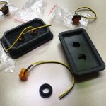
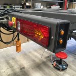
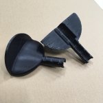
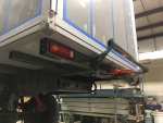
Turned my attention back to the 5"x3" rectangular tubing end caps on the back of the subframe that also house the tail lights. I'd already 3D printed a test piece awhile back but it was time to cap off this part of the build (pun intended). I also figured it was a good place to add a little more blinker lighting as this will ultimately be tucked slightly under the edges of the habitat.
IMG_8720.JPG
IMG_8725.JPG

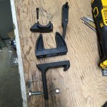
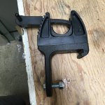
The lorry came with a brace/prop to help hold the cab in its raised position in the event the cab tilting hydraulics fail. This heavy, 4' long bar was previously stored inside on the cab's back wall but I've been scratching my head for the past couple years trying to find it a new home. A lightbulb moment occurred when I noticed one chassis rail beneath the cab was bare on top and had plenty of headroom to the underside of the cab in the closed position. I also had some strap clamps that came with the truck for holding down fire fighting implements in the back when under way. Throw in a little 3D printing magic, a handful of fasteners and voila!
IMG_8715.JPG
IMG_8716.JPG
IMG_8723.JPG
IMG_8724.JPG

- Sheik
 
Last edited:
Love you 3 D printing work, is it a hard plastic or metal?
Plastic of various types depending on the application.

Anything critical in nature is printed out of a nylon + carbon fiber filament that is remarkably robust. I've even printed replacement rear sway bar shackles out of the stuff (see post #256 & #272) but haven't been able to fully test them out yet due to limited driving since installation.

ASA is another plastic that has wonderful printing properties, UV inhibitors and comes in various colors.

I've used these two materials extensively (as well as ABS, PETG, Nylon, PLA) in a variety of projects for myself and engineering clientele. I'm still amazed I can create parts with these properties at my own shop for a fraction of the cost it would have been just a few years ago. Long live additive manufacturing!

- Sheik
 
I assume you have a bit more than a desktop 3D printer.
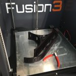
Fusion3 410. 12"x12"x14" print volume. Heated bed, hardened nozzles, enclosed print volume. Not rocket science but it has taken me a couple years to figure out how to get the best results from the various materials. You could get a printer as capable as mine for much cheaper but I chose to go with a more expensive USA-made printer for sake of tech support and company longevity (time will tell!).

Having a background in mechanical design and 3D modeling has been perfect fit for this sort of tool.

- Sheik
 
Lowly Update:

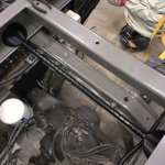
While fabricating the subframe I included a couple of cross-bars to help keep the winch cable from drooping down into the underlying components and tearing them out. In an effort to keep them from getting scoured by the cable and kicking off another round of cancerous rust I decided to armor the cross bars with some heavy nylon spiral wrap and 3D printed side buffers.
IMG_8733.JPG
IMG_8734.JPG

Worth it for the peace of mind once this area becomes an unreachable/uninspectable void with the habitat installed.

- Sheik
 
Last edited:
Lowly Update:

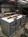
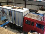
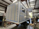
Finally got enough of the goodies between the chassis rails sorted out to install the habitat box on the previously fabricated and installed subframe. After much contemplation of various lifting options, I decided the best approach would be to lift from above using a spreader-bar frame and the rope hoist. This was rigged and tested using on-hand materials:
IMG_8746.JPG

We quickly determined the habitat was going to exceed the rope hoist's lifting ability and moved to a belt-and-suspenders option. We used a hi-lift jack to lift and block each end while taking up the slack from above using the hoist:
IMG_8749.JPG

I was somewhat confident the rope hoist could statically hold the habitat in the event the jack slipped or the incoming truck knocked out the jack stands. We put ExPo member mog's heavy duty jack stands to use until we maxed out their height. At this point we called in a friend that has a winch on his Jeep to provide more warm fuzzies in the lifting department as we approached the maximum height needed:
IMG_8138.jpg

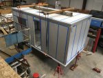
Jack stands were then swapped out for mog's high capacity screw jacks which allowed clearance for Lowly to back underneath. The upward process continued:
IMG_8751.JPG

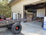
Once adequate height was achieved it was time for the lorry to start its journey under its new load:
IMG_8752.JPG

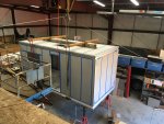
Before the box could be lowered the diesel tank had to be dropped from its intermediate, dangling location. The edges on the bottom had to be sealed/caulked and the protective cellophane removed. The lowering process then commenced, bit by bit. The truck and box weren't in perfect alignment so we had to slightly twist the box on its "moorings" to get the all-thread studs (see thread post #308) to align with the corresponding mount holes on the subframe. Everything came into line and we finished lowering the habitat box down onto the subframe:
IMG_8754.JPG

Used some bar clamps to scoot the box around on the subframe by about 1/8" and all the holes began lining up for bolting the subframe to the habitat. So glad to have this step behind us with how janky our lifting scenario was and no one got hurt. Took it slow and talked everything out before making each move to make sure people and their fingers were clear! Somehow the tires shrunk when the box got installed:
IMG_6188.jpg
IMG_6185.jpg

Big thanks to mog for the extended loan of his jack stands and screw jacks. Also, big thanks to the friends and family who assisted in getting this box set into place. Woo hoo!

- Sheik
 
Last edited:
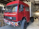
Lowly Update:

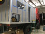
Templated, marked, drilled, circle cut, oscillating cut, jigsaw cut and box knife cut out the two rear cargo hatch openings. Went with the biggest size Arctic Tern had to offer and glad I did; we should easily be able to crawl into this storage compartment if the need arises. The boss-lady pointed out we will need to pack along a step-stool in order to access these areas as they are quite a ways off the ground!
IMG_8830.JPG

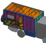
Design work continues in earnest with the under-habitat storage boxes and tanks currently out for quote. Habitat brush guards, roof-top awning, solar panel mounting and rear lifting mechanism is all integrated and currently being designed.
Screen Shot 2022-11-14 at 9.08.18 AM.png
Screen Shot 2022-11-14 at 9.08.37 AM.png

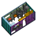
Interior layout and cabinetry has been 95% designed and the need to purchase materials is high on my priority list as baltic birch plywood is becoming a scarce commodity due to the current state of affairs between the US and Russia (baltic birch plywood should be called russian birch plywood).
Screen Shot 2022-11-14 at 9.18.10 AM.png

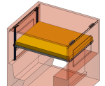
Vertical lift bed has been designed and its components are currently out for quote.
Screen Shot 2022-11-14 at 9.32.52 AM.png

Alot of digital progress; hopefully that will quickly result in physical progress!

- Sheik
 
Last edited:
Lowly Update:

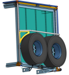
Design, testing and fabrication of components for the rear pivoting spare tire and bicycle frame continues. This will be another 1-off custom job using 3D printed parts. On paper (aka CAD) it should work great; who knows if it will function as well or consistently as I need it to in real life!

A center-mounted worm gear right angle reducer (parts repurposed from a Harbor Freight cable winch) will drive a shaft out to both bottom rear corners of the habitat. At each corner the shaft will turn a spool of 1" webbing that travels up the aluminum tubing to the top of the frame where it exits and mounts to the top corner of the habitat. As the spool creates slack in the webbing the frame will pivot downward at the bottom corners, lowering down the bicycles mounted on top and, on rare occasion, one of the spares that will be sitting on the back of the habitat.
Screen Shot 2022-12-02 at 8.29.41 PM.png

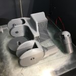
After designing all the components in 3D and buying all of the parts I couldn't fabricate, I began 3D printing some test parts to see if this system might actually work.
IMG_8915.JPG

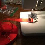
I then fabricated the webbing assembly using the bar-tacking skills I've mastered from my rafting/camping equipment side-hustle.
IMG_8908.JPG

Torque will be transferred from the worm-gear driven shaft to the webbing spool via a set-screw collar with flats milled on each side. I was able to purchase stainless steel collars but still needed the flats machined into them.
IMG_8916.JPG

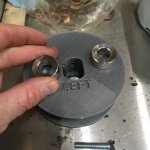
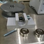
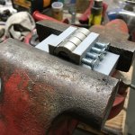
With Christmas just around the corner and knowing I'll likely be laying out serious coin to buy Lego sets for my two boys, I figured it was time to save some money and do some country-style machining. I designed and 3D printed a jig to hold all 4 collars in the correct orientation and serve as a material removal indicator.
IMG_8917.JPG
IMG_8918.JPG

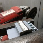
The angle grinder was then put to use, grinding down the exposed sides of the set collars until they were flush with the face of the jig.
IMG_8919.JPG

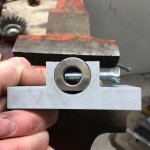
A quick flip of the collars and the other side was ready for the same treatment.
IMG_8920.JPG

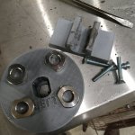
The modified collars didn't come out machine-shop precise, but it will be good enough to transfer the torque AND saved me some Lego money!
IMG_8921.JPG

- Sheik
 
Last edited:
Lowly Update:

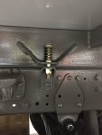
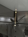
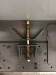
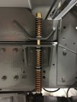
Die springs, grade 8 hardware and 3D printed spacers have been installed between the truck chassis and the habitat subframe. A bit of high school trigonometry and algebra along with some rough estimates on required spring rates resulted in the following 4 assemblies on each side of the truck.
IMG_8994.JPG
IMG_8995.JPG
IMG_8996.JPG
IMG_8998.JPG

The shorter spring stack, the closer to the hard mount between the chassis and subframe toward the back end of the truck. Maximum travel can occur at the largest spring stack to the tune of 2.5". These springs were sourced from McMaster-Carr and are the "Gold (Heavy Load Rating)" variety with 5/8" internal hole. Hoping the spring rates are enough to allow for subframe-chassis movement while keeping the habitat from swaying too much.

- Sheik
 
Last edited:
Lowly Update:

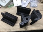
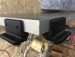
The 3D printer has been kept busy printing various bits and bobs for the exterior of the habitat. These little carbon fiber+nylon beauties are mounting brackets for the solar panels. They utilize the geometry of the panel's edges along with the t-slot geometry on the habitat's aluminum extruded edges.
IMG_9014.jpg
IMG_9015.jpg

The ability to mount things directly to the habitat (using the t-slots a la 80/20 extrusion) without having to use adhesive or drill holes in the panels was a big selling point in the RV Globetrekker product. More 3D printing goodness to come; stay tuned!

- Sheik
 
Last edited:
Forum statistics

Threads
188,342
Messages
2,905,815
Members
229,959
Latest member
bdpkauai
Top