In my quest to keep things as low as possible in my F450+Sunrader build, I have dreamt up a plan to build my flatbed so as to keep things as low as possible.
My flatbed will be spring mounted, similar to a M35's system:

My flatbed will be similar to Boblynch's in the F550 Flatbed build thread:

Boblynch went with the 2x4 steel main beams, that rest on the frame rails, usually with wood strips between them. He did this in order to keep things low, some larger trucks have 6" tall beams. In his illustration the darker color indicates 2x4, the rest is 2x2.
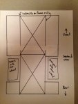
I want to keep things even lower, if possible. To do this I came up with the idea of two X's within the flatbed framework. All of the steel is 2x2 in my concept and the "outriggers" are welded to the side of the main beams, except for the front-most and rear-most that span the entire width of the flatbed. (sorry for the lousy sketch, not to scale, 1:12 scale approx):

The main purpose of the main beams being larger than the rest is to stiffen the flatbed. The X's will stiffen the flatbed, the question is if it is enough.
If you want to know more about this, I found this link helpful. It covers chassis design and the link takes you specifically to the torsional rigidity pages.
To those with real world, fabrication or engineering knowledge, please let me know your thoughts. Can I get the stiffness I need with this design? Because the flatbed will be spring mounted it will not have as much twist put into it, but it will receive stress. I also wonder about the number of X's, I suppose it could be anywhere from 1 to 3. Thanks a lot.
My flatbed will be spring mounted, similar to a M35's system:

My flatbed will be similar to Boblynch's in the F550 Flatbed build thread:

Boblynch went with the 2x4 steel main beams, that rest on the frame rails, usually with wood strips between them. He did this in order to keep things low, some larger trucks have 6" tall beams. In his illustration the darker color indicates 2x4, the rest is 2x2.
I want to keep things even lower, if possible. To do this I came up with the idea of two X's within the flatbed framework. All of the steel is 2x2 in my concept and the "outriggers" are welded to the side of the main beams, except for the front-most and rear-most that span the entire width of the flatbed. (sorry for the lousy sketch, not to scale, 1:12 scale approx):

The main purpose of the main beams being larger than the rest is to stiffen the flatbed. The X's will stiffen the flatbed, the question is if it is enough.
If you want to know more about this, I found this link helpful. It covers chassis design and the link takes you specifically to the torsional rigidity pages.
To those with real world, fabrication or engineering knowledge, please let me know your thoughts. Can I get the stiffness I need with this design? Because the flatbed will be spring mounted it will not have as much twist put into it, but it will receive stress. I also wonder about the number of X's, I suppose it could be anywhere from 1 to 3. Thanks a lot.
