My Dual Battery Setup- Diagram Check

ntsqd

Heretic Car Camper
Switch said:
snip.....
I'm inclined to think that the frame would offer less resistance than an #2 copper wire. MTC
Not in my experience. I've been through this several times with various race cars with relocated batteries. They ground near the battery to save the weight of the ground cable. Then the car has slow cranking speed problems. Grounding to the engine block has yet to fail to fix this.

Copper (0.00000170 ohm-cm) is a much better conductor than steel (0.0000159 ohm-cm). The only possible way that the frame could be a better conductor would be thru a larger cross section. Looking at those resistivity numbers the cross section would need to be ~10 times larger. That's not very likely. If the actual current path crosses any welds, those have a surprisingly high resistance.
 

Switch

Observer
ntsqd said:
Not in my experience. I've been through this several times with various race cars with relocated batteries. They ground near the battery to save the weight of the ground cable. Then the car has slow cranking speed problems. Grounding to the engine block has yet to fail to fix this.

Copper (0.00000170 ohm-cm) is a much better conductor than steel (0.0000159 ohm-cm). The only possible way that the frame could be a better conductor would be thru a larger cross section. Looking at those resistivity numbers the cross section would need to be ~10 times larger. That's not very likely. If the actual current path crosses any welds, those have a surprisingly high resistance.

That is an excellent point. And so we learn. Thanks.
 

keezer36

Adventurer
ntsqd,

Though I could not find much about this see-saw effect between the batteries, if I understand it, I would think that a sense resistor as on the Hellroaring units would prevent this, they have a tolerance of .2 VDC.
Another point, wouldn't this also occur simply by having two different batteries especially if one is older than the other and does not hold a charge as well?
What do you think?

One other thing I thought of was with two different ground points (frame/engine), if there was resistance or resistance built up over time, would there be a voltage measured negative post to negative post?
 

ntsqd

Heretic Car Camper
This is sort of getting away from the original topic, my apologies for that.

If you connect two batteries in parallel they will equalize their charge state. The battery with the higher potential (voltage) will charge the battery with the lower potential. With perfect conductors they will reach a state of equilibrium. Note that this equilibrium will happen thru both conductors, not just the one on the positive side.
Even superconductors aren't perfect. Any resistance, no matter how small, will dissipate some of the stored energy as heat. It may be such a small amount of heat that it is difficult to detect at home (because the resistance is tiny), but it does happen.

I'm not entirely clear on the actual mechanism of the see-saw effect. My best guess is that the high potential battery pushes enough current into the low potential battery that there is an effect similar to inertia. Think of this as an ocean wave. There is always a low point in the water behind each wave that is lower than the level of the ocean itself. The water in the wave's peak had to come from somewhere. The high battery will actually flow enough current towards the low battery that it's own charge level is reduced to a point below that of the other battery. Which then, in turn, tries to charge the formerly high battery. And back and forth that goes until neither battery has enough charge to do anything. If either the conduction path on the positive side or the negative side has some measurable resistance then this process is accelerated because a resistor drops voltage so the low battery "looks" even lower to the high battery than it really is. Compound that with the heat dissipation caused by the resistance.
Note that batteries have an internal resistance. (Don't try to measure this with a normal Ohm meter - neither of you will be happy with the results.) If the two batteries connected together don't have the same internal resistance then the external conductors could be perfect and the see-saw effect would still occur at an accelerated rate. This is the root of wanting two batteries as identical as possible. Any resistance in the circuit makes one battery "look" to be at a lower charge state to the other battery. If they are both at the same level of charge then they each "look" to be the same voltage to the other battery and no current flow takes place.

If you add some sort of disconnector to either conductor you stop the process. Which is one of the purposes of the ACR or the Hell-Roaring product, a simple diode bridge ("battery isolator"), or even the old constant duty charging solenoid.

None of this addresses how the batteries interact with an external charging source. That is a huge topic by itself. Suffice to say that the standard automotive alternator & regulator are at the low end of what is available and possible. egn posted a link to amplepower a while back. Some of their stuff is very interesting.
 

Switch

Observer
Dusty T. said:
What really has me paralyzed in the design/decision phase of this project, is determining what size wire and fuse combo to run to the aux battery. Since the battery will certainly be bed-mounted, #2 AWG looks like a good choice to cover the ten to twelve foot distance with minimal voltage drop. The 80 amp or smaller fuse would prevent too much current from flowing, but wouldn't it blow when trying to charge a discharged battery since #2 wire is good up to 200 amps?

Talking with Mike from Hellroaring (hopefully I'm not twisting his information around here), he recommended a smaller gauge wire, i.e. #8 as a charging wire for the aux battery. This would prevent the battery from drawing more current during its charge cycle, which could overwork my 80-amp alternator- supposing it is 80 amps. I would like to use the Optima D31T rated at 75 amp hours. I also called Optima and asked about the required amps to charge this battery should it be completely discharged. I didn't get a very direct answer, but their tech guy thought my alternator would do just fine.
Sorry if this sounds ridiculous, but I'm stumped on what size wire to go with, especially if I want to use the charging wire to also power some accessories up front in the cab without incurring too much voltage drop.

I bit my tounge yesterday hoping someone with more experience than I would chime in on this point. Maybe my stab at this will at least draw some attention to your dilemma.

Short answer:
You have a choice between #2 wire w/ 150A fuse OR #4 wire w/ 100A fuse OR #6 wire w/ 80A fuse. DO NOT use a smaller wire/fuse than #6. If it were my project, I would go with the #2 wire w/ 150A fuse.

Long answer:
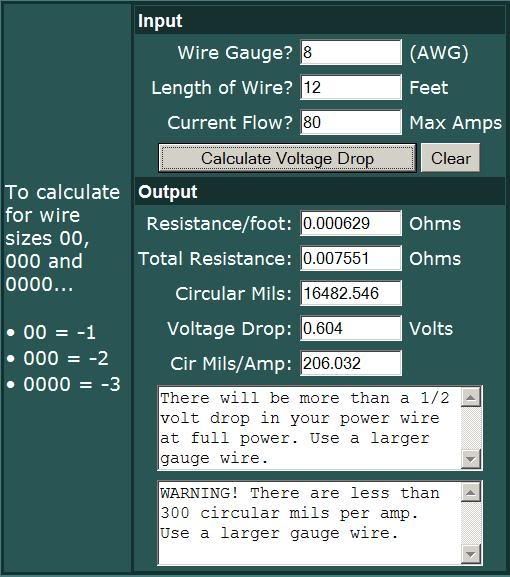
I think you should size wire based on safety, cost, and appliction. I used this tool for sizing wire: http://www.bcae1.com/wire.htm
In the following example the wire size is too small:
wiresize.jpg

With a lenght of 12 feet you can safely use any gauge less than #8. A larger wire cost more and will be more hassel to install. If it were my project, I would not worry about cost and use #2 to minimize voltage drop. I would use the best wire I could find, tin coated, made with lots of fine wire threads so it can bend easily. I'd also protect it with split conduit tubing.


The fuse has two functions: safety and to protect the equipment. It does not regulate curent as implied by your question. I am unaware of an electrical code for cars but the electrical code for boats specifies that the fuse should be within something like 18" or 24" from a power source. If a short circuit occurs the fuse will blow but your truck will not burn. The hellroaring site mentioned that typical batteries draw about 60A when recharging. So an 80A would be fine but then you need to consider the opposite case, power needed when cranking and for running your car. Practically speaking the fuse is really only protecting wire in this application so a larger fuse will just be less likely to blow under normal use. For example if your primary battery is drained down and you want to start your truck, the second battery will be pumping out current to charge the primary battery AND crank the engine AND run lights etc. I used the 150A fuse and fuse holder sold by hellroaring. For your application, even though you could go with a smaller wire and smaller fuse, the only reason I can see to do so is cost of labor and materials.
If you value your time, you know that most of the cost of these projects is time spent on design, followed by time spent doing the work, followed by materials. Time spent trying to save a few bucks on materials is time wasted, since you are not going to do 10,000 dual battery projects. Hope this helps.
 

Dusty T.

Observer
Switch said:
Short answer:
You have a choice between #2 wire w/ 150A fuse OR #4 wire w/ 100A fuse OR #6 wire w/ 80A fuse. DO NOT use a smaller wire/fuse than #6. If it were my project, I would go with the #2 wire w/ 150A fuse.


I certainly agree with your points. I'm looking to go with #2 or #4 wire due to the additional length. This definitely helps reduce voltage drop, and will allow me to piggyback on that same charging wire to run power back to the cab from the aux battery to run the stereo, sub, CB, mini fridge, etc.... I guess I see the smaller 80 amp fuse preventing the alternator from being overloaded, but it's probably overkill.

I actually used the bcae1 wire site to aid me in my battery system design. That is an excellent quick reference guide to building electrical systems.

The hellroaring site mentioned that typical batteries draw about 60A when recharging. So an 80A would be fine but then you need to consider the opposite case, power needed when cranking and for running your car.

Where did you pick up this tidbit of information? Mike from HR seems like a great source of info for this system, but their website is a bit muddled. 60A still seems like alot to charge a battery but if there is some chart or reference for this, I'd like to see it!

Switch- I checked out your dual battery system on ttora. http://www.ttora.com/forum/showthread.php?t=67738
Now, you mention that the HR isolator is the incorrect isolator and should be the 95150, and not the 95300. The isolator in the photo looks like a 95300. Do you mean this is the incorrect isolator for your application? From what I read, your setup uses the second battery as a backup ONLY- not aux. Seems to me that the 95300 would be perfect for this setup. Pardon my misunderstanding regarding this, and thanks in advance for the clarification!


I really appreciate everyone's feedback here. This is probably the millionth post regarding dual battery setups so your patience has been much appreciated. I'll definitely take pictures when the setup is complete. It's always fun to compare notes.
 

keezer36

Adventurer
I believe the diodes of the isolators are rated at 90A. If you're sure your alternator is 80A, then your fine with running the larger wire. The reason the Hellroaring website recommends the 8AWG wire on the 95150 is the smaller diameter wire will limit the current through the isolator should your alternator be pushing more than 90A.

The 90150 is for hooking up your aux load on the second battery. The 95300 is for using your second battery primarily as a backup for cranking. If you used the 95300, you would have to hook up your engine off aux loads on the cranking battery. This is due to the diode configuration of the two isolators being different. If you ran a 95300 and had aux loads running on the second battery, there is nothing stopping the drain of the primary. Notice the 95300 has three posts and the 95150 has two. With the 95300, you can double your current carrying capacity because you have two posts available for hooking up the second battery.

If you plan on running aux loads with the engine off, the 95150 is the one to use and those aux loads should be hooked up to the second battery only.
 

Switch

Observer
Dusty T. said:
I certainly agree with your points. I'm looking to go with #2 or #4 wire due to the additional length. This definitely helps reduce voltage drop, and will allow me to piggyback on that same charging wire to run power back to the cab from the aux battery to run the stereo, sub, CB, mini fridge, etc.... I guess I see the smaller 80 amp fuse preventing the alternator from being overloaded, but it's probably overkill.

I actually used the bcae1 wire site to aid me in my battery system design. That is an excellent quick reference guide to building electrical systems.


Where did you pick up this tidbit of information? Mike from HR seems like a great source of info for this system, but their website is a bit muddled. 60A still seems like alot to charge a battery but if there is some chart or reference for this, I'd like to see it!

Switch- I checked out your dual battery system on ttora. http://www.ttora.com/forum/showthread.php?t=67738
Now, you mention that the HR isolator is the incorrect isolator and should be the 95150, and not the 95300. The isolator in the photo looks like a 95300. Do you mean this is the incorrect isolator for your application? From what I read, your setup uses the second battery as a backup ONLY- not aux. Seems to me that the 95300 would be perfect for this setup. Pardon my misunderstanding regarding this, and thanks in advance for the clarification!


I really appreciate everyone's feedback here. This is probably the millionth post regarding dual battery setups so your patience has been much appreciated. I'll definitely take pictures when the setup is complete. It's always fun to compare notes.

I have a 95300. Before I installed the PC1700 I used the PC925 for aux power which is NOT the way the 95300 was supposed to be used. Sorry about the confusion on this point.

On this page it says "A starting battery rarely accepts more than 60 amps from an alternator"
http://www.hellroaring.com/bic75150.php
 

ntsqd

Heretic Car Camper
I have a hard time with sizing a wire to be a current limiter. Unless it is designed to be so (Fuseable Link) the potential for a fire is great. Just not a good idea.

Size the wire to deal with the max current that can flow in the circuit. Nothing less. Fuse or breaker the circuit to prevent over-current events.

Also, note that modern vehicles are designed with the alternator as the primary current provider, not the battery. The battery is really only intended for starting the engine. We alter that intent when we starting adding all of our various overlanding gear and asking that the battery support them with the engine off.
 
Last edited:

Dusty T.

Observer
ntsqd said:
I have a hard time with sizing a wire to be a current limiter. Unless it is designed to be so (Fuseable Link) the potential for a fire is great. Just not a good idea.

Size the wire to deal with the max current that can flow in the circuit. Nothing less. Fuse or breaker the circuit to prevent over-current events.

Also, note that modern vehicles are designed with the alternator as the primary current provider, not the battery. The battery is really only intended for starting the engine. We alter that intent when we starting adding all of our various overlanding gear and asking that the battery support them with the engine off.

I know, it seems strange to size a charge wire this way, but the closest analogy I could think of is the size hose you are using to fill a bucket. Of course, the smaller, #8 gauge charge wire would have a 50 amp fuse at each end.


I received some info back from Hellroaring regarding the charge wire size. Very quick customer service! See the attached PDF for their recommendation.

I'm still tempted to go with between #6 to #2 wire to charge the aux battery. As mentioned earlier, I would like to use ONE wire between the main and aux battery for both charging and providing power to the accessory fuse box in the cab. The #8 wire sounds dangerously small for this task. Otherwise, it seems that I would need to run one #8 wire to charge the battery, and run another #6 wire back to the fuse box in the cab. Seems like even more overkill than my setup already is!
 

ntsqd

Heretic Car Camper
If the battery's maximum rate of charge is 60 amps, then regardless of the alternator's capacity the circuit will only flow 60 amps at most. I see their point, I'm not buying it for a single aux. battery. Maybe for a large battery bank comprised of several to many batteries in parallel. I still think the basic approach is wrong, but I've no experience with such systems.
 

Dusty T.

Observer
ntsqd said:
If the battery's maximum rate of charge is 60 amps, then regardless of the alternator's capacity the circuit will only flow 60 amps at most. I see their point, I'm not buying it for a single aux. battery. Maybe for a large battery bank comprised of several to many batteries in parallel. I still think the basic approach is wrong, but I've no experience with such systems.


That's where I'm at as well. This would leave 20A at the very least to run the engine and some other accessories during MAX charge for the aux battery.

You know, rather than me beating a dead horse with ampacity, voltage drops, and wire sizes, I need put a parts list together with some #4 wire, a 60-80 amp fuse, and start building this sucker!
 

ntsqd

Heretic Car Camper
ntsqd said:
If the battery's maximum rate of charge is 60 amps, then regardless of the alternator's capacity the circuit will only flow 60 amps at most. I see their point, I'm not buying it for a single aux. battery. Maybe for a large battery bank comprised of several to many batteries in parallel. I still think the basic approach is wrong, but I've no experience with such
Large

Fixed it.


You know, rather than me beating a dead horse with ampacity, voltage drops, and wire sizes, I need put a parts list together with some #4 wire, a 60-80 amp fuse, and start building this sucker!
WHAT!? You mean this wasn't just a mental exercise?
LOL........

Looking at it this way, say the aux battery is a 200Amp-Hr unit. That's one amp for 200 hours, or (in theory, not sure the conductors would live there very long) 200 amps for one hour. So with a 100 amp alternator the worst possible case would require maximum output for 2 hours (ignoring what such a thing would actually do to the battery). An automotive alternator can probably do that, but it's pushing pretty hard.
With a multi-battery aux bank of, say, 1000 amp-hrs that alternator will expire before a full state of charge is achieved.
In that context what they are saying makes sense. I just disagree with their solution.
 
Last edited:

Dusty T.

Observer
ntsqd said:
WHAT!? You mean this wasn't just a mental exercise?
LOL........

Looking at it this way, say the aux battery is a 200Amp-Hr unit. That's one amp for 200 hours, or (in theory, not sure the conductors would live there very long) 200 amps for one hour. So with a 100 amp alternator the worst possible case would require maximum output for 2 hours

I've had a headache all week thinking about this!

Wow, 200 Ah. The Yellow Top I'm looking at is 75 Ah- about the same size as the aux battery used on my last setup. I failed to mention my last setup did use a #8 charging wire which seemed to work okay, but I wasn't using that same wire to also run additional accessories off of that battery. It was strictly for charging.....

So conceptually, it would likely take less than one hour to fully charge the 75 Ah aux battery without running the alternator at full capacity during that period of time. As the battery would charge, its current draw would gradually decrease until it was fully charged. Perhaps a voltage drop could occur when the alternator is maxed out, thus causing the isolator to stop charging the aux battery? Just a thought, anyway.....

I was also considering the 95300B isolator to simply run everything off of the "main" battery and have the second battery for startup purposes only. Either way, there will still be a drained battery needing a charge. HR's standpoint with this setup is that there is only ONE battery being drained since the backup starting battery is completely isolated from loads. The aux system, however, has the potential of having both batteries drained from their respective loads, hence Hellroaring recommends the smaller charging wire to prevent two (instead of one) drained batteries from overloading the charging system. Personally, I see two drained batteries as a very unusual occurrence for my setup since the stereo will almost always be connected to the aux battery anyway. Not to mention Toyota has gone through great lengths to make running down the main battery nearly impossible by automatically switching off accessories when the key is removed.

In the meantime I'm going to get back to designing and slowly building this setup over the next couple weeks or possibly months as time permits. I certainly can't wait to get a more improved aux battery system up and running again for those future back country trips!
 

Dusty T.

Observer
Cable Routing.....

It's been a busy few weeks between work, and squeezing in a little trip to Nevada's Black Rock Desert for the Tacos first camping trip. Good Times!

Looking for a second opinion on cable routing..... I was debating the location of the aux battery and decided on mounting it on the passenger side, front end of the bed for better weight balancing.

That said, I'll probably run the #4 charge cable up under the bed closer to the muffler than I'd like to. It will attach to the underside of the bed where the end of the tape measure is shown (see attached photo). What I'm wondering is whether this is dangerously close (within 6") to the hot exhaust? I do plan on wrapping the wire in plastic loom and covering it with that adhesive metallic fiberglass insulation to help deflect some of the radiant heat coming off the exhaust. The only other routing I can think of is running the wire up into the bed behind the bedliner..... I personally can't see this cable being exposed to higher temps than under the hood, but just wanted to be sure this isn't a recipe for disaster.

Thanks for the help once again! :eek:
 

Forum statistics

Threads
188,398
Messages
2,904,164
Members
230,274
Latest member
mbauerus1
Top