You are using an out of date browser. It may not display this or other websites correctly.
You should upgrade or use an alternative browser.
You should upgrade or use an alternative browser.
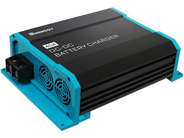
New DC to DC Charger From Renogy-20 amps or 40 amps-Flooded/AGM/GEL/Lithium
- Thread starter continuecrushing
- Start date
TommyArgh
Member
That would help out tremendously! The last thing Id want to do is melt my rig to the ground.It would be good for an expert on here to do a quick wiring diagram...
You could see where my concerns come into play right? I just want to be certain that the power coming from the alternator and the power coming in from the panel doesnt create an overload on any of the components or even melt the battery.
Photobug
Well-known member
A BMS is a collection of functionality to protect the bank.
Just buying a product that claims to do it all for you
vs putting together a collection of devices yourself,
is not fundamentally different.
I have a voltage readout that I have calibrated or at least double checked against a mult-tester to know how much it is off. I now have my Smart Solar charger, but have just started figuring it out. I was thinking of adding an amp meter. What else would you recommend for individual devices to monitor battery functions/status?
DaveInDenver
Middle Income Semi-Redneck
You have the basic instruments you need. Measuring voltage gives a rough state that along with measuring the current that flows in during charge and out during discharge gives you what you need. The critical piece of the puzzle is a way to record it over time, e.g. the Kill-A-Watt type devices.I have a voltage readout that I have calibrated or at least double checked against a mult-tester to know how much it is off. I now have my Smart Solar charger, but have just started figuring it out. I was thinking of adding an amp meter. What else would you recommend for individual devices to monitor battery functions/status?
To help keep things straight for those willing to spend time advising, I think each member/setup should start a dedicated thread, giving details / links to what they have, drawings if helpful, and some specific Qs / concerns to get started.
Too much confusion and overhead having everything jumbled together in one thread, that is no linger really about the topic it was originally started for, and pretty well covered.
IMO anyway.
Too much confusion and overhead having everything jumbled together in one thread, that is no linger really about the topic it was originally started for, and pretty well covered.
IMO anyway.
Photobug
Well-known member
You have the basic instruments you need. Measuring voltage gives a rough state that along with measuring the current that flows in during charge and out during discharge gives you what you need. The critical piece of the puzzle is a way to record it over time, e.g. the Kill-A-Watt type devices.
I have a kill a watt but it is an AC model. I just bought a higher end multi tester. I had created a cigarette plug pigtail to use my old multi-tester to determine the accurate voltage of the battery. Now I am using the new multi-tester to test my voltage with my newly installed Anderson plugs. Would some type of shunt allow me to use this multitester to determine amp draw or should I install a separate amp meter?
continuecrushing
Member
I have a kill a watt but it is an AC model. I just bought a higher end multi tester. I had created a cigarette plug pigtail to use my old multi-tester to determine the accurate voltage of the battery. Now I am using the new multi-tester to test my voltage with my newly installed Anderson plugs. Would some type of shunt allow me to use this multitester to determine amp draw or should I install a separate amp meter?
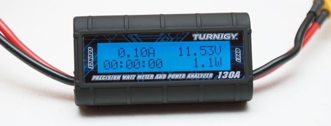
If you want really simple you could get one of these off amazon for 15-17 bucks. It's pretty basic, but gives you battery voltage/power used. I have a victron shunt/gauge but I still use this thing plugged into my fridge(s) so I know battery voltage at the fridge and how much power its used. Granted, it won't track how much power/charge has gone into the battery, but it'll give you a good idea of how much power you've removed from the battery if you place it between the battery and whatever stuff is drawing from the battery. It says 150a on the meter, but I sure as heck wouldn't put that much current through it, just fyi.
Before I had my victron, I used the power meter linked abpve and the AH output shown on my renogy charge controller (solar) to have a ballpark of how much power the battery has left/has been used. Isn't 100% accurate, but helped when determining power.
I did this:
in the morning, check to see how many AH I had used already (from the meter). Let's just say 20ah
Plug in my solar (shows 0 ah charged, because it wasn't plugged in)
In the enening, check everything.
Power meter might show I used 40ah total meaning I used about 20ah from the battery since checking in morning
Solar charge controler would show it charged 30ah that day, meaning I didn't decrease any battery capacity during the day.
Granted, this is a very simplified way of looking at it (not taking into account other power draw uses/charge effiecency etc) but you probably get the idea.
Last edited:
Best Ah counters are external shunt-based (sized appropriately) and will also function as true Battery Monitors, calculating SoC% as accurately as possible, taking into account programmable Charge Efficiency Factor, Peukert coefficient, declining capacity as the bank ages etc.
Not cheap of course, but long-lasting and reliable, may include control of external contactors, integration with BMS, central control systems
The cheapest basic but decent coulomb counters I've seen from China / eBay etc start at $50 or so, can be made "portable" by inserting Andersins at key benchmarking locations whether for key loads or sources around the system.
One built into a clamping type ammeter would be nice, haven't seen one yet.
DaveInDenver
Middle Income Semi-Redneck
This one works pretty well for under $30. The Hall effect sensor isn't clamp-on so you do have to anticipate when you're cabling or at least be able to disconnect and route it though later. There's other less than perfect things, the meter isn't sealed, the sensor wiring is pretty short as built, there's no Peukert correction. But it's a basic starting place. You can set an initial battery capacity and topped voltage, there's an over- and under-voltage alarm, current measurement can be calibrated and it only draws about 4mA so it's fairly light on what it demands.Best Ah counters are external shunt-based (sized appropriately) and will also function as true Battery Monitors, calculating SoC% as accurately as possible, taking into account programmable Charge Efficiency Factor, Peukert coefficient, declining capacity as the bank ages etc.
Not cheap of course, but long-lasting and reliable, may include control of external contactors, integration with BMS, central control systems
The cheapest basic but decent coulomb counters I've seen from China / eBay etc start at $50 or so, can be made "portable" by inserting Andersins at key benchmarking locations whether for key loads or sources around the system.
One built into a clamping type ammeter would be nice, haven't seen one yet.
DROK DC 0-300V 200A STN LCD Display Digital Multimeter Voltage Ampere Power Energy Ammeter Voltmeter Battery Volt Amp Meter AH Monitor Panel with Hall Sensor ... - - Amazon.com
DROK DC 0-300V 200A STN LCD Display Digital Multimeter Voltage Ampere Power Energy Ammeter Voltmeter Battery Volt Amp Meter AH Monitor Panel with Hall Sensor ... - - Amazon.com
smile.amazon.com
shade
Well-known member
Looks good enough for me to log consumption by my fridge and figure out what I need from a system. ?This one works pretty well for under $30. The Hall effect sensor isn't clamp-on so you do have to anticipate when you're cabling or at least be able to disconnect and route it though later. There's other less than perfect things, the meter isn't sealed, the sensor wiring is pretty short as built, there's no Peukert correction. But it's a basic starting place. You can set an initial battery capacity and topped voltage, there's an over- and under-voltage alarm, current measurement can be calibrated and it only draws about 4mA so it's fairly light on what it demands.
DROK DC 0-300V 200A STN LCD Display Digital Multimeter Voltage Ampere Power Energy Ammeter Voltmeter Battery Volt Amp Meter AH Monitor Panel with Hall Sensor ... - - Amazon.com
DROK DC 0-300V 200A STN LCD Display Digital Multimeter Voltage Ampere Power Energy Ammeter Voltmeter Battery Volt Amp Meter AH Monitor Panel with Hall Sensor ... - - Amazon.comsmile.amazon.com
teotwaki
Excelsior!
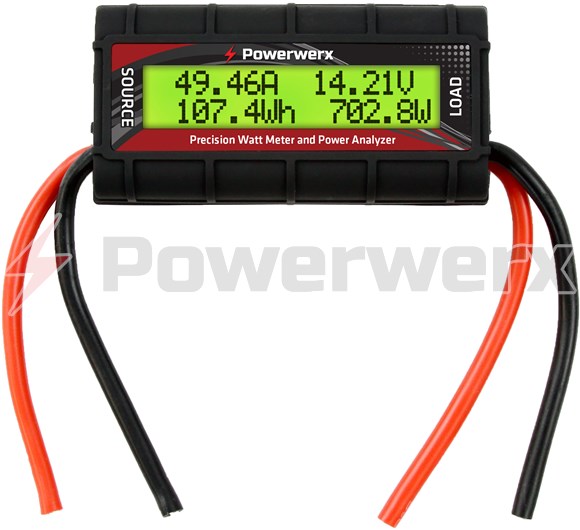
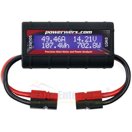
As you elude anyone considering this meter (or the other versions such as sold by Powerwerx for example) need to know that it can only run in the forward direction, e.g. from source to load. Letting current run backward trying to track the total cycle of a battery will damage it.
Can you cite a source for that claim about damage where they explain why? Makes no sense to me that a solid state sensor will care about current flow direction . I have the original "Watt's Up" that is widely copied and here is what they have to say about reverse currents:
Will a "backwards" or reverse connection damage the "Watt's Up"? E.g. connecting a charger to the LOAD side and a battery to the SOURCE? What will the display read?
No. Connecting in this manner causes current to flow in the reverse direction, but will cause no damage up to the rated current of the meter. However, while connected this way, the meter will not indicate the actual current nor any value derived from the current i.e. Watts, Amp hours or Watt hours. E.g. the Amps and Watts will read 0.
Any accumulated Ah or Wh displayed will not increase further until power again flows from SOURCE to LOAD, i.e. in the forward direction (meaning current is flowing in the black wires from LOAD to SOURCE).
About measuring current flow in both directions (e.g. bi-directional measurement)?
The "Watt's Up" and Doc Wattson meters only measure current flowing in the black (negative) wire from their LOAD side to their SOURCE side as labeled on the meter's case. Current flowing in the opposite direction is not measured and does not affect accumulated or peak readings. Current flowing in the red wires is not measured at all.
To do a net current flow "bi-directional" current measurements (e.g. measure both directions of current flow) at one point in a circuit, we recommend using two meters connected together and oriented LOAD to LOAD (or SOURCE to SOURCE) as that is a more flexible and easily interpretted arrangement, than a bidirectional meter usually offers.
Alternatively, the meters can be mounted in separate parts of the system to measure two currents simulaneously. For example, the charge current into a battery and the discharge current out. Those currents may differ and this arrangement will show that. In this case meters are connected as usual ensuring that the current to be monitored is flowing in the correct direction in the black leads.
These dual meter arrangements allow independent measurement of the two current flows and their peak values. It also allows their respective accumulated values (e.g. Ah, Wh) to be reset separately. A bonus is that the voltages of the two separate systems can be independently monitored as well as the currents.
Last edited:
teotwaki
Excelsior!
Renogy converter is on sale for $116.99

 www.newegg.com

Renogy 12V DC to DC On-Board Battery Charger - Newegg.com
Buy Renogy 12V DC to DC On-Board Battery Charger with fast shipping and top-rated customer service. Once you know, you Newegg!
teotwaki
Excelsior!
I will cite what I think is a reliable source, the Powerwerx version of it.

Powerwerx Watt Meter, DC Inline Power Analyzer, 45A Continuous, 12 Gauge, Bare Wire Ends
Measuring capacity up to 60V and 100A. 12 gauge bare wire leads. Bright blue backlit LCD display. Measures 8 electrical parameters: Amps, Volts, Watts, Amp-hours, Watt-hours, Peak Amps, Minimum Volts (Sag), Peak Watts. No configuration, works automatically!powerwerx.com
There are a number of reasons why this might cause a potential damage. Depends on the sensor type, is it Hall Effect or shunt, the sensor amplifier topology, the voltage reference you give it. If you expect a signal to only be sinking and it changes to sourcing you may violate absolute maximums across a differential amp.
Then practically speaking, having a reverse polarity protection is potentially expensive and may impact the measurement or raise the quiescent current drawn, so you can avoid it by defining the use case and shifting responsibility to the user.
I agree with you that well designed the device shouldn't be damaged but its not completely surprising that for a variety of reasons when dealing with relatively large currents such as this is intended to measure it wouldn't.
I don't see any reason for damage.
Resistive shunts are limited from damage by staying within the power rating of the shunt, peak or steady state currents. Resistors don't care which way you pass current through. Differential amplifiers used for current sense won't be damaged if the polarity across the shunt resistor is flipped. We are talking millivolts developed across the shunt even at peak currents.
I also have one of those Chicom clones that says "150A" across the front so I opened it up and it obviously uses a resistive shunt. I can imagine that the output of the current sense amp is calibrated to vary between 0v and the PCB's main supply and if the current across the shunt is reversed the amp's output stays at the bottom of its range and the A2D converter is reading that as zero amps. But nothing is damaged.
Reverse current does not raise the quiescent current drawn. The internal circuits of these devices still see voltage at a correct polarity and operate at the same current. I'm sure I can verify that easily enough on the bench.
Linear Hall effect sensors used for DC current measurement are non-contact devices. The current conductor passes through a magnetic core that concentrates the conductor’s magnetic field. The Hall effect device is mounted in the core at a right angle to the concentrated magnetic field. If the field is reversed the Hall effect device simply produces no output but internally there is no element I can read about to be damaged by a reversed magnetic field. I doubt most of these hobby power meters use Hall effect devices.
I put reverse current through both of my meters all the time without damage. I suspect the Powerwerx people are probably wrong because I would bet they simply have a re-labled Chinese clone that is internally made exactly the same as mine: a subboard for current and voltage measurement plugged into the LCD display board.


shade
Well-known member
Dave, I really appreciate you pointing this meter out. The more I look into it, the more useful it seems. It's a cheap way to add an independent backup to whatever other monitoring is offered by your charge controller or other devices.This one works pretty well for under $30. The Hall effect sensor isn't clamp-on so you do have to anticipate when you're cabling or at least be able to disconnect and route it though later. There's other less than perfect things, the meter isn't sealed, the sensor wiring is pretty short as built, there's no Peukert correction. But it's a basic starting place. You can set an initial battery capacity and topped voltage, there's an over- and under-voltage alarm, current measurement can be calibrated and it only draws about 4mA so it's fairly light on what it demands.
DROK DC 0-300V 200A STN LCD Display Digital Multimeter Voltage Ampere Power Energy Ammeter Voltmeter Battery Volt Amp Meter AH Monitor Panel with Hall Sensor ... - - Amazon.com
DROK DC 0-300V 200A STN LCD Display Digital Multimeter Voltage Ampere Power Energy Ammeter Voltmeter Battery Volt Amp Meter AH Monitor Panel with Hall Sensor ... - - Amazon.comsmile.amazon.com
Here's a link to the DROK page on the WLS-PVA200, and to the manual. I'm standardizing with Anderson Powerpole connectors, so I can make up a short pigtail to insert the sensor into any circuit for logging. I've also read about people extending the wiring to the sensor by several feet. DROK has this to say about using an extension. Plenty of options are available:
"We are sorry we don't have longer cable. If you need longer one, it should be shield cable. It should be easy to be found. Connector specification is XH2.54-3P."
Similar threads
- Replies
- 14
- Views
- 2K
- Replies
- 0
- Views
- 459
- Replies
- 0
- Views
- 594
- Replies
- 5
- Views
- 4K
