New DC to DC Charger From Renogy-20 amps or 40 amps-Flooded/AGM/GEL/Lithium

TommyArgh

Member
That is just shorthand for the engine circuit.

The actual charge source usually wired to that circuit is the alternator.

Others may include a solar controller, a mains charger, in turn powered off either shore power or a portable genset.

Which may currently be wired to that Starter circuit, or directly to the House bank.

The DCDC should **not** be configured to actually draw any power from the Starter battery itself, nor from any battery

it should only be turned on when a charge source is active.

Sorry I misunderstood your comment. I will definitely not be using the battery as a source. Instead I may tap into the factory bed mounted inverter. It will only switch on while the vehicle is running.

If I tapped into the solar controller for a source for the DCDC would it act the same as if I sourced from a battery seeing that it always on?
 

luthj

Engineer In Residence
There is nothing wrong with attaching directly to the starter battery. You need to make sure the charger is only running when the engine is. So triggering from the D+ alternator running, or ignition is required. Most DC-DC units have the ability to take an on/off input signal this way. Otherwise they are like the Ctek units, which switch themselves automatically when they sense a charge source.
 

shade

Well-known member
Instead I may tap into the factory bed mounted inverter. It will only switch on while the vehicle is running.
If you have a Toyota Tacoma, even though the 120VAC outlet is located in the bed, the inverter is located under the center console/armrest next to the driver's seat. At least, that's where it lives in a 2nd gen.
 

john61ct

Adventurer
Sorry I misunderstood your comment. I will definitely not be using the battery as a source.
I did not mean to imply that you choose where the energy comes from by **where you attach** the power input in the circuit, that is not the case.

Yes attaching directly to the Starter battery is fine, as is any other robust connection in the alt/starter engine circuit, all should be equivalent.

If a SC were hooked in there somewhere as well, then that becomes a source on that side in addition to the alternator.

But it sounds like the alt is your only source on that side, so D+ or any other IGN switched circuit will power on your DCDC just fine.

> If I tapped into the solar controller for a source for the DCDC would it act the same as if I sourced from a battery seeing that it always on

I do not understand your question

If you install solar, it usually would go directly to the House battery.

If you want the solar to automatically charge both sides, then you need a VSR in addition to the DCDC.
 

Trstevens

New member
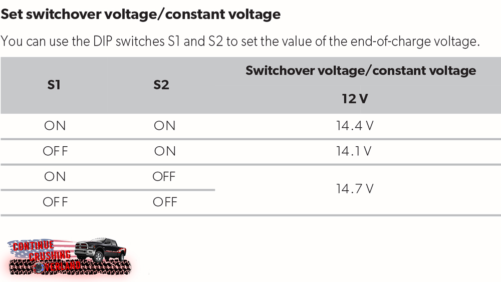
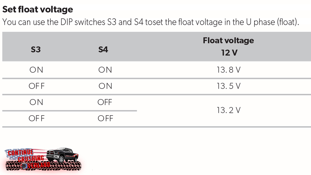
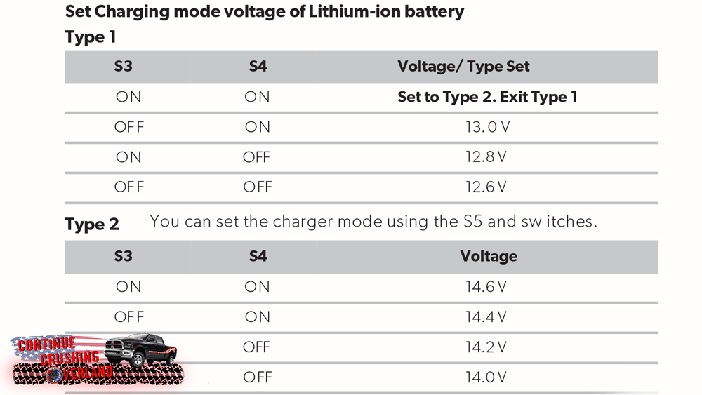
Here are the tables from Renogy. Also, shouldn't you have a BMS or something running/managing the LifepO4? So "end" charge voltage won't matter? Anyway, here they are:
renogy-dc-to-dc-charger-continue-crushing-overland-dip-switch-setting-charged-voltage.jpg

renogy-dc-to-dc-charger-continue-crushing-overland-dip-switch-setting-float-voltage.jpg

renogy-dc-to-dc-charger-continue-crushing-overland-dip-switch-setting-lithium.jpg
Thanks for posting this. I’ve got one 40a paired with one Renogy 170ah lithium and cannot get the soc higher then 12.6...anyone find success and share settings for the dip switches?
 

john61ct

Adventurer
Something's broken, that's not a configuration issue.

You need to get an ammeter - or even better an Ah-counter - as well as your known-accurate DMM.

Forget the alternator source, for testing use a power supply or charger off shore power as input to your DCDC, at least 20A .

14.4V is likely what you need to see at the bank to be considered Full - check that - and maybe even hold it there for some time to give the balancing time to kick in - try to find out the "start-balance" voltage setpoint of the internal BMS.
 

ATskier

New member
Does this charger trickle-draw off the alternator side or house side?

anyone ever seen a dead starter battery while hooked through one of these to a lithium house battery?
 

WVI

Adventurer
Does this charger trickle-draw off the alternator side or house side?

anyone ever seen a dead starter battery while hooked through one of these to a lithium house battery?


I had not thought of that....Good question.
 

john61ct

Adventurer
Does this charger trickle-draw off the alternator side or house side?

What you choose to use for the input side circuit is completely up to you, you can "flip them around" to go in the other direction if needed, and

this has nothing to do with which DCDC unit you use.

An alternator is just one option for input source, you may not even need a battery on the source circuit.

> anyone ever seen a dead starter battery while hooked through one of these to a lithium house battery?

Maybe I do not understand the question?

Of course if you leave the unit on when there is no charge source active, any DCDC unit will suck flat any battery on the source side, to the extent there is demand on the target / output side, or ling term just from parasitic loads.

It is up to the installer to design automated mechanisms to ensure this doesn't happen, or the owner will need to remember to isolate / combine manually - not IMO a good idea.

Some DCDC units have built in IGN switching, or a VSR/ACR for solar / genset charging.

IMO all should have all three options included.

And ideally user-custom adjustable output setpoints.
 

ATskier

New member
Thanks for the replies. Sorry I just shot off a quick question on behalf of a stranded friend 1,500 miles away. Now after a little research I see these don't draw current and sense level of voltage to switch, rather have a line to ignition.

Its possible whoever set this up for my pal didn't run that line to a switched 12 volt ignition source and the charger is connected all the time.
 
Last edited:

Buddha.

Finally in expo white.
Here are the tables from Renogy. Also, shouldn't you have a BMS or something running/managing the LifepO4? So "end" charge voltage won't matter? Anyway, here they are:
renogy-dc-to-dc-charger-continue-crushing-overland-dip-switch-setting-charged-voltage.jpg

renogy-dc-to-dc-charger-continue-crushing-overland-dip-switch-setting-float-voltage.jpg

renogy-dc-to-dc-charger-continue-crushing-overland-dip-switch-setting-lithium.jpg
Does anyone know what settings I’d use for flooded lead acid golf cart batteries?
 

john61ct

Adventurer
From Deka's specs:

older:
BULK: 7.425V, ABSORB: 7.275V, FLOAT: 6.75V, EQUALIZE: 7.875V

newer: extrapolated to 12V:
CV / Absorption Voltage = 14.4V - 14.7V
CC / Bulk can be a bit higher
Absorption End Point = Current change over 1 hour period of less than 0.1A
or just use 0.005C if that's easier
Float Voltage = 13.8V - 14.1V
 

luthj

Engineer In Residence
From Deka's specs:

older:
BULK: 7.425V, ABSORB: 7.275V, FLOAT: 6.75V, EQUALIZE: 7.875V

newer: extrapolated to 12V:
CV / Absorption Voltage = 14.4V - 14.7V
CC / Bulk can be a bit higher
Absorption End Point = Current change over 1 hour period of less than 0.1A
or just use 0.005C if that's easier
Float Voltage = 13.8V - 14.1V

For daily cycling I would err on the higher side of those ranges. When on float service for several months, going to the lower end will improve the batteries life slightly by reducing grid corrosion.
 

john61ct

Adventurer
Note do not allow automatic Equalization.

For Trojan, their specs are online.

In a PSOC scenario, if you have trouble getting up to 100% SoC (as per CV endAmps) then better to go a bit higher on Absorb / CV

e.g. from 14.6V up to say 14.8V

Of course all the above assumes normal deep cycling FLA GCs, not sealed pseudo Wally world types.

Any decent manufacturer has detailed tech docs published and knowledgeable support engineers readily available to discuss these details.
 

Forum statistics

Threads
188,004
Messages
2,900,934
Members
229,233
Latest member
cwhit5
Top