Review: Auxbeam 12-gang Bluetooth switch panel with remote

jscherb

Expedition Leader
Part 1

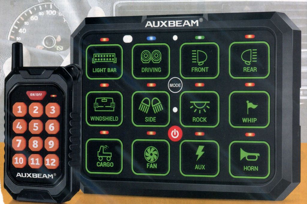
Recently Auxbeam upped the game in switch panels when they released their new 12-gang panel. It's got a Bluetooth interface to a smartphone app, a handheld remote control, and 100 amps total capacity.
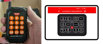
RemoteControlPanel.jpg


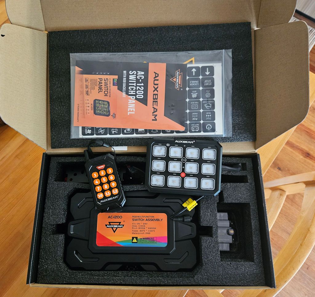
A few weeks ago they sent me one to test and review. The kit includes the switch panel, a handheld remote, the control unit, a 100amp circuit breaker, and various mounting brackets, wiring and other hardware.
AC1200Box.jpg


I did test installs in both my LJ and my JKU; what follows is the JK installation. If anyone is interested in the details of the TJ installation I can share that as well.

Installing the Auxbeam AC-1200 Switch Panel in a JK Wrangler

Installing the Auxbeam AC-1200 switch panel involves a number of steps:

  • Mounting the control box
  • Powering the control box
  • Connecting the switch panel to the control box through the firewall
  • Mounting the switch panel in the cockpit

Mounting the Control Box

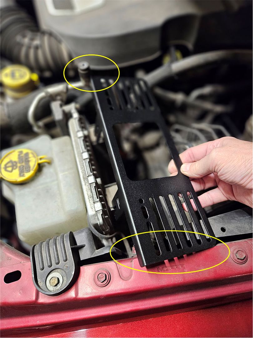
Unfortunately, the mounting bracket provided with the AC-1200 12-gang switch panel system is just too long to fit in what is probably the only place in the engine compartment that the large control box for the system can be installed. In the photo below you can see that it’s too long – it overhangs the fender and on the other end it interferes with one of the hard A/C lines.
BracketTooLong.jpg


The location shown in the photo above is really the best place to mount the large AC-1200 control box in the crowded JK engine compartment and since the mounting bracket that Auxbeam supplies with the kit just doesn’t work in that location, I made my own. If anyone needs the pattern to make a similar bracket let me know and I can share it. The new bracket:
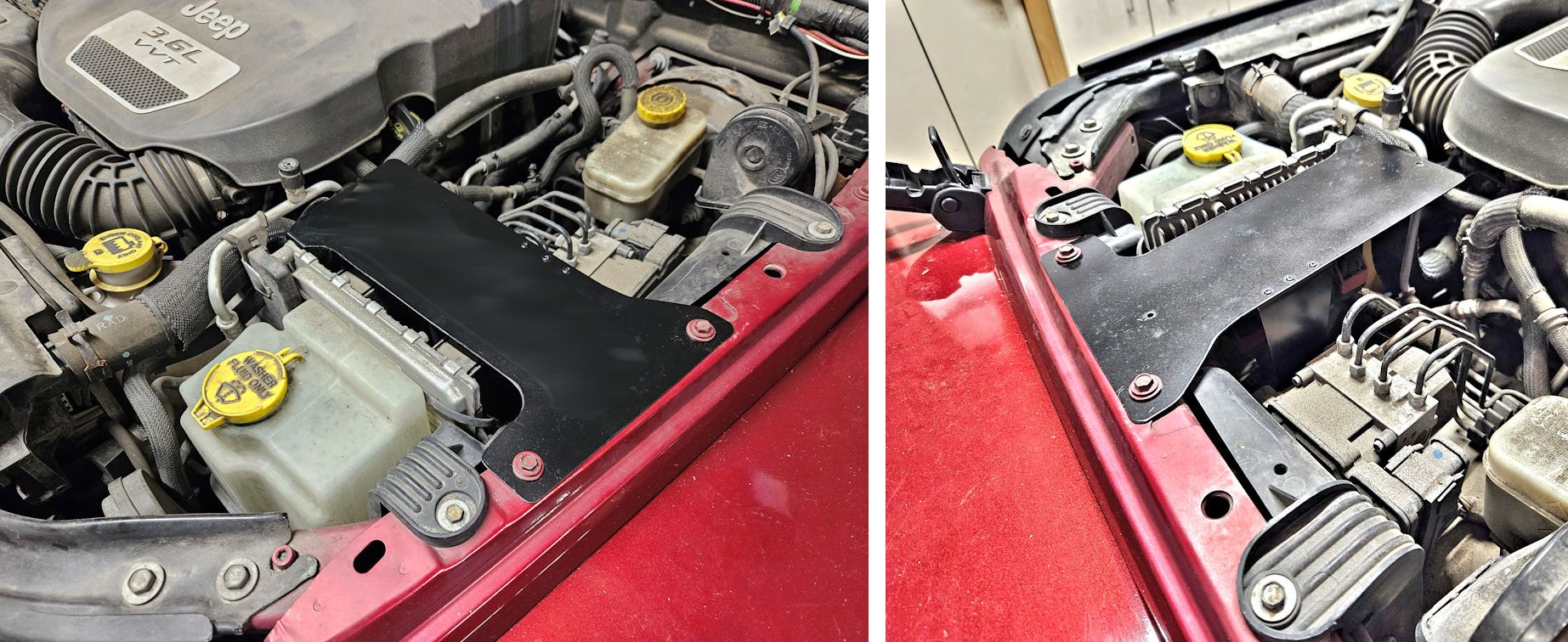
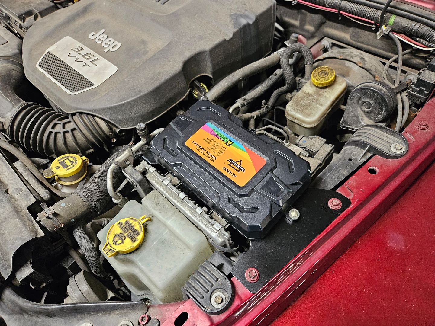
JKBracketMounted.jpg


20231019_134504.jpg


Powering The Control Box

There are two power connections to the control box – switched power to operate the box, and higher current power to operate any accessories connected to the system.

Auxbeam supplies heavy-gauge cables to connect the control box to the Jeep’s battery to power accessories connected to the system. Unfortunately since the best place to install the control box is further away from the battery than the length of the supplied cables. Longer cables must be used, and they must be of a gauge heavy enough to carry the 100 amps of current that the control box is capable of supplying to accessories.

A good way to make new cables is to start with a set of jumper cables. Stores like Walmart offer relatively inexpensive jumper cables which are an excellent source of the require wire – this set offers 4-gauge wire and retails for less than $20: https://www.walmart.com/ip/Everstar...motive-Booster-Cables-Jumper-Cables/182918724. Those cables are 20 feet long; only about 6 feet will be required to connect the control box to the battery so if you remove one of the clamps from the jumper cables, cut 6’ of wire from the 20’ and reinstall the clamps you will end up with a 14’ set of jumper cables and enough wire to connect the control box.

Also needed will be 4 ring terminals to terminate each end of the 6’ cables. Auto parts stores like AutoZone and many electrical supply stores offer ring terminals like those shown below – the accept 4-gauge wire and have a 3/8” I.D. ring which is perfect for connecting to the control box and the battery.

RingTerminal.jpg


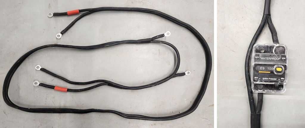
A completed cable to connect the control box to the battery made from part of a set of jumper cables can look like the one in the photo below. Red heat-shrink tubing has been added to one of the wires to indicate that it is the positive connection; black heat shrink tubing has also been shrunk over the ring terminals to protect them. The heat shrink tubing isn’t strictly necessary but it makes for a more professional looking cable.
LongerPowerCable3.jpg


There’s a break in the positive side of the cable with terminals on each end of the break, that’s where the circuit breaker will be inserted into the circuit, as shown in the photo at right.


Supplying Operating Power to the Control Box

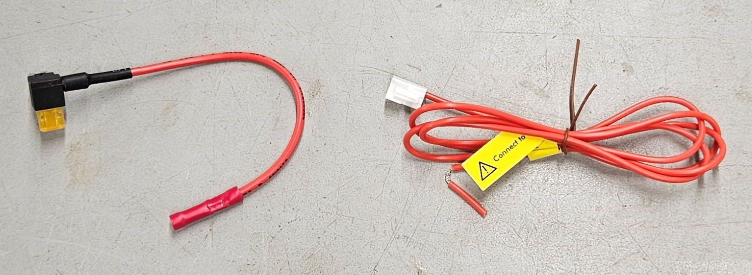
The kit came with two fairly short wires for connecting power to the control box. One piece has a fuse adapter on it and the other piece has a plug for the control box. The fuse adapter makes it easy to supply switched power to the control box, but additional wire will be required in almost all installations to connect between these two pieces. Wiring option 1:
WiringType1.jpg


When I met with Auxbeam at the SEMA Show, they gave me an alternate wiring solution. This one has a ring terminal on one end for direct connection to the battery and an inline fuse, a plug on the other end for the control box, and a switch in the middle for turning power to the control box on or off. The wires are long enough for most installations. This solution might be better for a camping/overlanding vehicle in which accessories might need to be powered at the campsite when the vehicle isn’t running, but one must remember to turn the switch off if the system isn’t to be used when the engine isn’t running. Or, the ring terminal can be removed and that end of the wire can be connected to a switched circuit if the system isn’t to be used when the engine isn’t running. Wiring option 2:
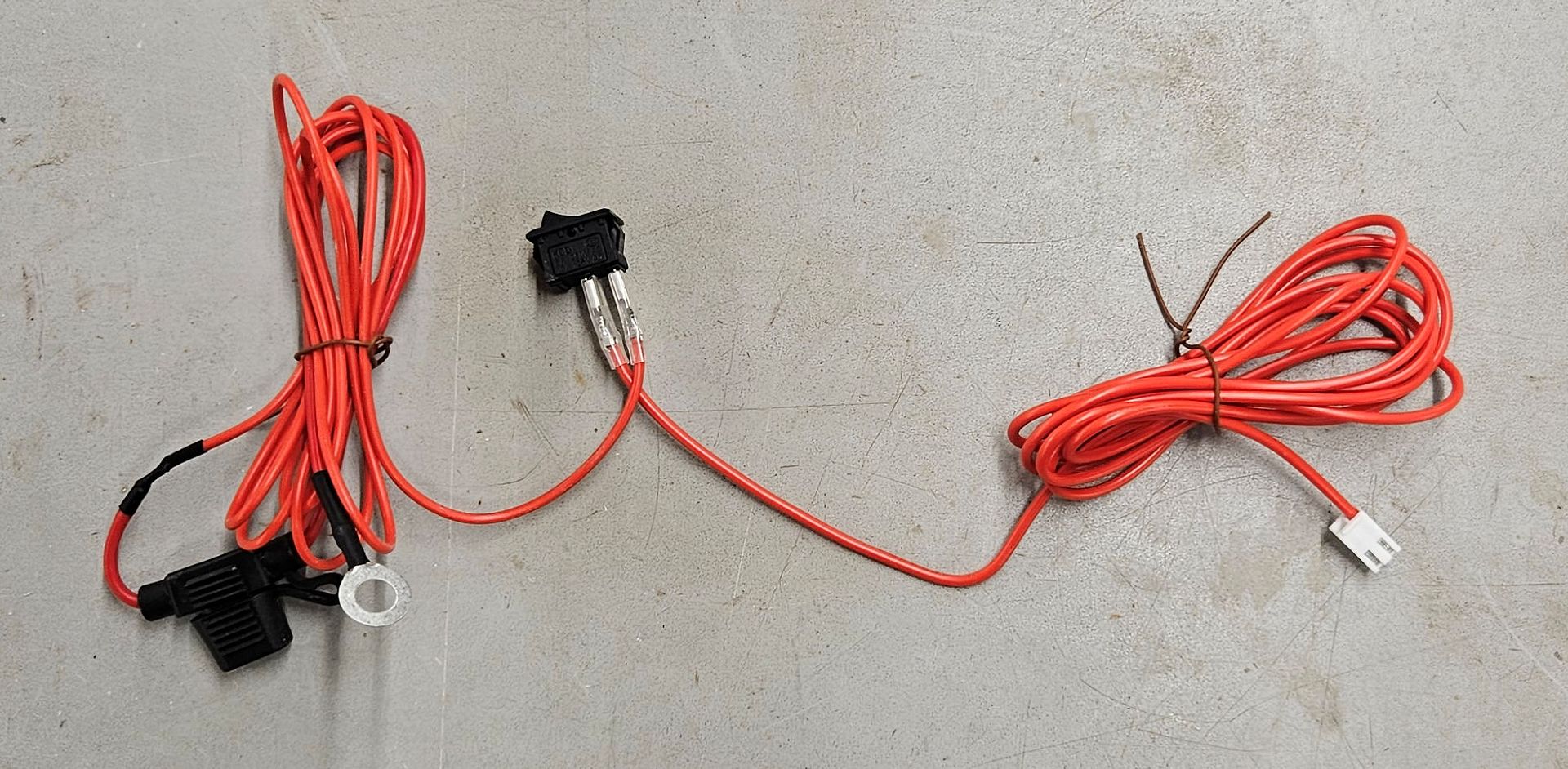
WiringType2.jpg


Whichever wiring solution your kit comes with, both wiring solutions have their benefits and drawbacks but either one will work fine in most implementations.

Wiring option 1:

The other power connection required goes to the Jeep’s fuse panel and provides switched power to operate the system. Switched power is power that’s only active when the ignition switch is in the on/run position and is recommended so the system doesn’t draw power when the engine isn’t running, which might drain the battery.

In a JK Wrangler, switched power can be sourced in the “TIPM”, which is Jeep’s term for the fuse box in the engine compartment. TIPM stands for Totally Integrated Power Module, and inside it is a lot more than just the fuse panel, but for our purposes for this installation all we care about is the fuse panel.

Auxbeam supplies a fuse adapter with the kit; remove the fuse from position M7 in the fuse panel, plug the fuse tap into that position and insert the fuse removed from position M7 into the open slot in the fuse tap and shown in the photo below. Fuse M7 protects the auxiliary power outlet in the Jeep, and since it’s switched power (although this can be overridden to constant power in some models with a dash setting) it’s a good place to provide power to operate the switch panel system. Note: verify that the setting for this circuit is switched power, not constant. Using constant power for the operation of the switch panel system isn’t recommended because it could drain the battery when the engine isn’t running.
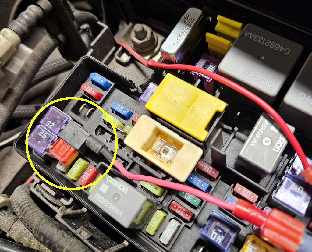
JKAccessoryPowerTap.jpg


Auxbeam provides a short length of red wire with a two-pin plug on one end, this plug goes into a two-pin location inside the control box. The other end of this red wire must connect to the loose end of the fuse tap installed above, and an extra length of red wire is required because the combination of the fuse tap wire and the control box wire is too short to reach between them. Auto parts stores sell red 16-gauge wire for this purpose.

Wiring option 2:

With the second wiring option, the ring terminal is connected to the positive terminal of the battery, and the wires that connect to the switch get routed through the firewall as will be described below; the switch can be mounted in any convenient place on or under the dash. The switch is used to control power to operate the system and should be switched off when the Jeep isn’t running.
 

jscherb

Expedition Leader
Part 2

Connecting the Switch Panel to the Control Box through the firewall

Since the control box is in the engine compartment and the switch panel will be in the cockpit, the switch panel cable must be run through the firewall. There are two places on the JK firewall where holes a provided for running wires into the cockpit.

Firewall Hole on the Battery Side:

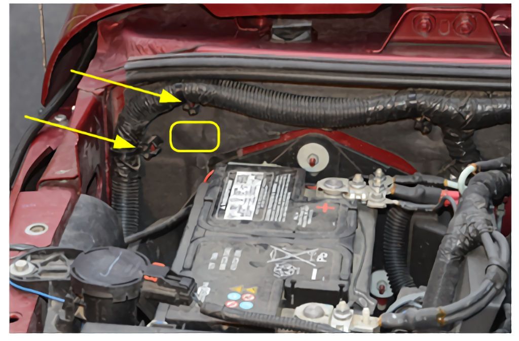
A good place to run the wire that connects the switch panel to the control box through the JK firewall is through a hole that exists in the firewall just behind the battery (marked by the square in the photo below). To access it pull the plastic cable straps (arrows) off the studs in the firewall and pull back cable and the firewall insulation. The hole is covered with a piece of soft black self-stick plastic that can be peeled back.

JKFirewallHole1.jpg


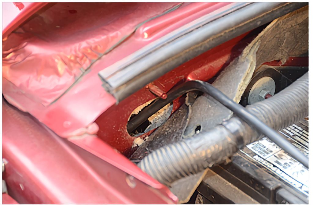
Once the insulation and self-stick plastic are out of the way, cut a hole in the insulation on the inside of the firewall that’s big enough to push the plug through. The insulation is backed with plastic, so you’ll need to cut a hole through the plastic. There won’t be much
room to push the plug through the hole, so it may help to pull out some of the insulation with needle-nose pliers to make more room. When the hole is large enough, push the wire through monitor plug first; when enough has been pushed through you can reach under the dash and pull it through from that side. Pull the wire through until most of the wire is inside the Jeep.

JKFirewallHole2.jpg


Once the wire is routed through the firewall, press the firewall insulation back into place and replace the cable straps on the studs.


Firewall Hole on the Driver (Left) Side:

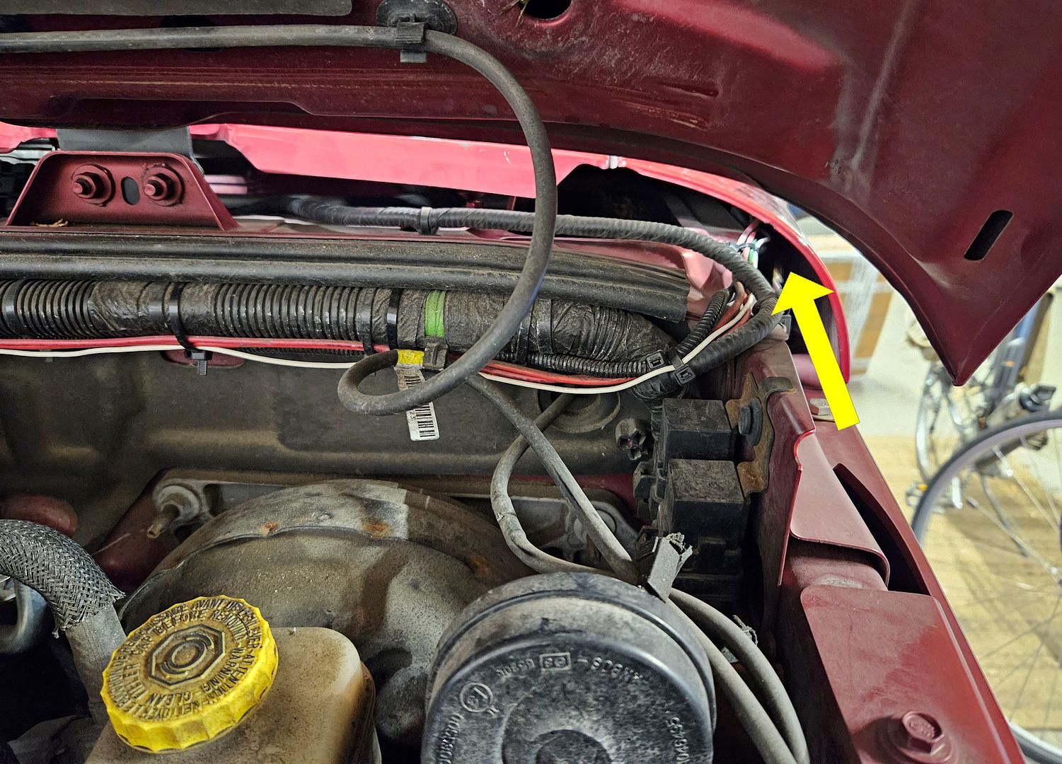
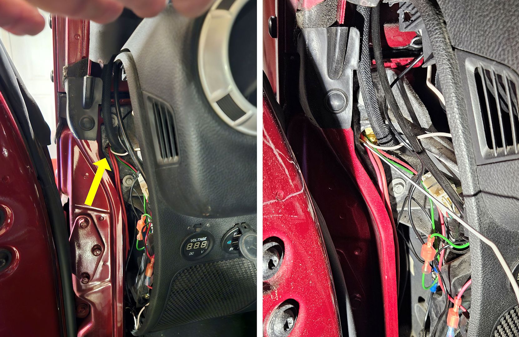
This location is best used with the option 2 wiring that has a switch to be installed in the cockpit. The wires for the switch can be run into the cockpit is in the upper left corner, just under the curved part of the fender. The arrow shows the location:

JKFirewall1.jpg


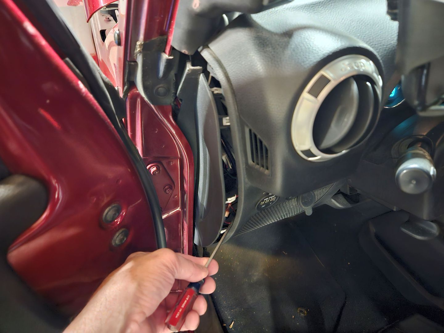
To use this location, begin by removing the trim panel on the side of the dash:

JKFirewall2.jpg


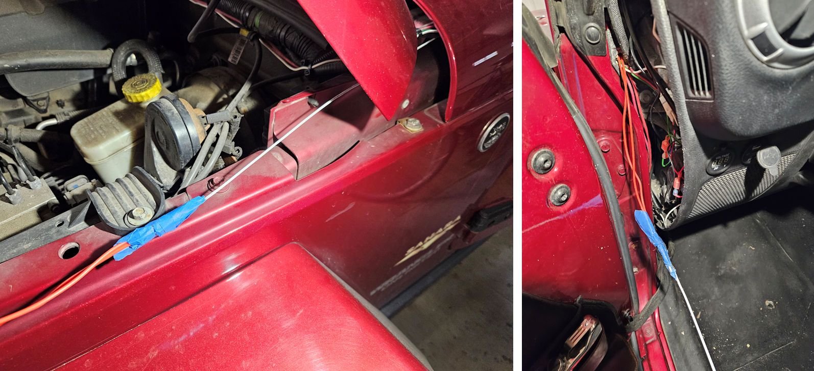
The best way to run wires through this location is to push a coat hanger or other stiff wire into the cockpit from the engine compartment side. From the factory this location has foam in it, so the stiff wire will need to be pushed through the foam. The arrow in the photo at left shows the hole the wires will go through, in the photo at right a coat hanger has been pushed through that hole into the engine compartment.

JKFirewall3.jpg


Once the stiff wire is through, the wires to be run into the cockpit can be taped to the stiff wire and pulled through from the cockpit side. Once in the cockpit the wires can be reattached to the switch and the switch can be mounted in a convenient location.

JKFirewall.jpg


If you’re using wiring option 2 with the switch, remove the switch from the wires before pulling them through and reattach the switch once the ends of the wires have been pulled into the cockpit. The switch can be mounted on the lower dash panel; this photo shows that panel with some electrical outlets already mounted there; another hole is easily added for mounting the switch.

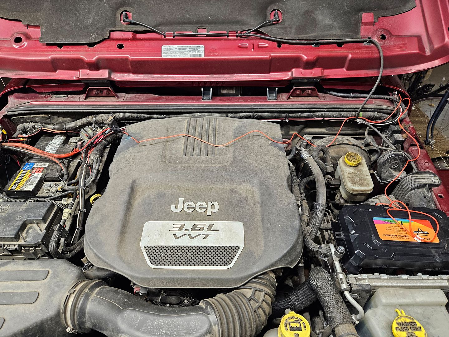
This next photo shows the wires from the option 2 wiring laying temporarily in place in the engine compartment – the end with the ring terminal and fuse runs over to the battery and the end with the connector for the control box runs to the control box.

JKFirewall4.jpg


The photo above shows the end with the ring terminal routed to the positive terminal of the battery. Alternately, that wire could be connected into the fuse box with a fuse adapter if you wanted the system to be operated on switched power so it turns off when the engine isn’t running.
 

jscherb

Expedition Leader
Part 3

Installing the Switch Panel

Once the switch panel cable is run into the cockpit, it’s time to decide where to mount the switch panel.

Having 12 oversize switch buttons, it’s a fairly large panel to find a place for within reach of the driver in a JK.

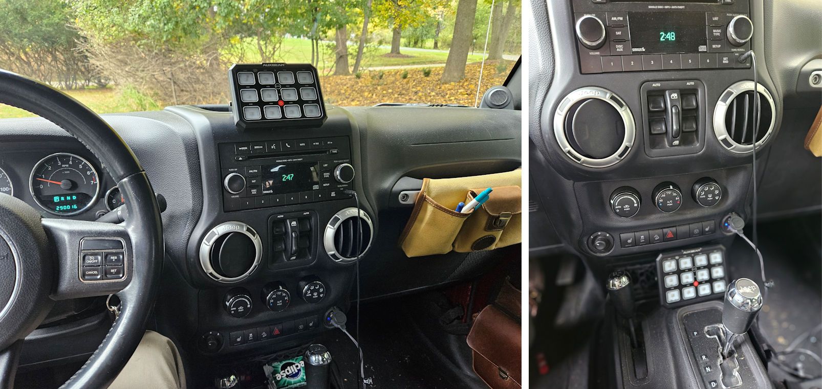
Some people mount it on the trim panel below the instrument panel and steering wheel, but mounted there it can be hard to see and may be a distraction while driving, so that may not be the best location. (A switch panel in this location is shown on page 5 of the AC-1200 instructions.) Two other locations that work in the JK are shown in the photos below – it can be mounted to the dash either in front of or behind the dash-top tray, or it can be mounted just ahead of the shifter on the center console.

PanelLocationsJK.jpg


There are two other options for controlling accessories connected to the system…

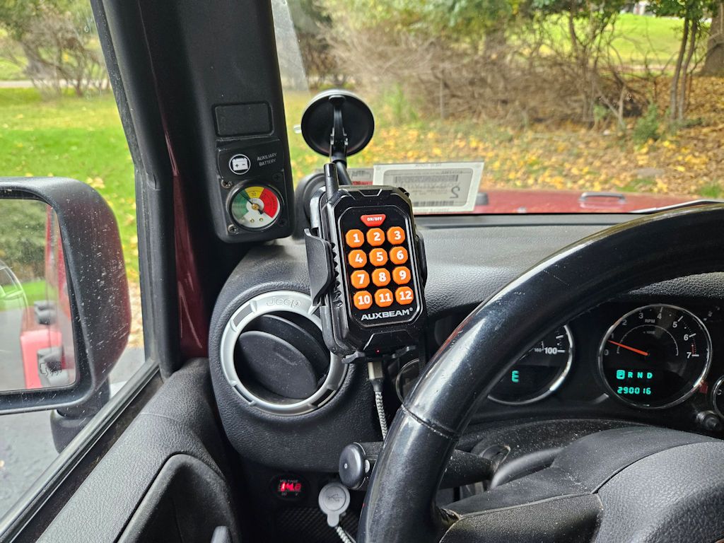
One option is to use the supplied remote control. In this next photo, the remote is sitting in a cell phone holder that’s mounted to the windshield of the TJ with a suction mount. The remote can turn any of the 12 circuits on or off, the only thing you don’t get with this option is the labels on the keys so you will have to remember what each button does. But an additional feature you do get is the ability to control the circuits remotely – say for example you’ve got campsite accessories connected to the Auxbeam system, you can turn them on or off while sitting at the campfire. Perhaps campsite lights attached to the roof rack of the Jeep?

RemoteInJK.jpg


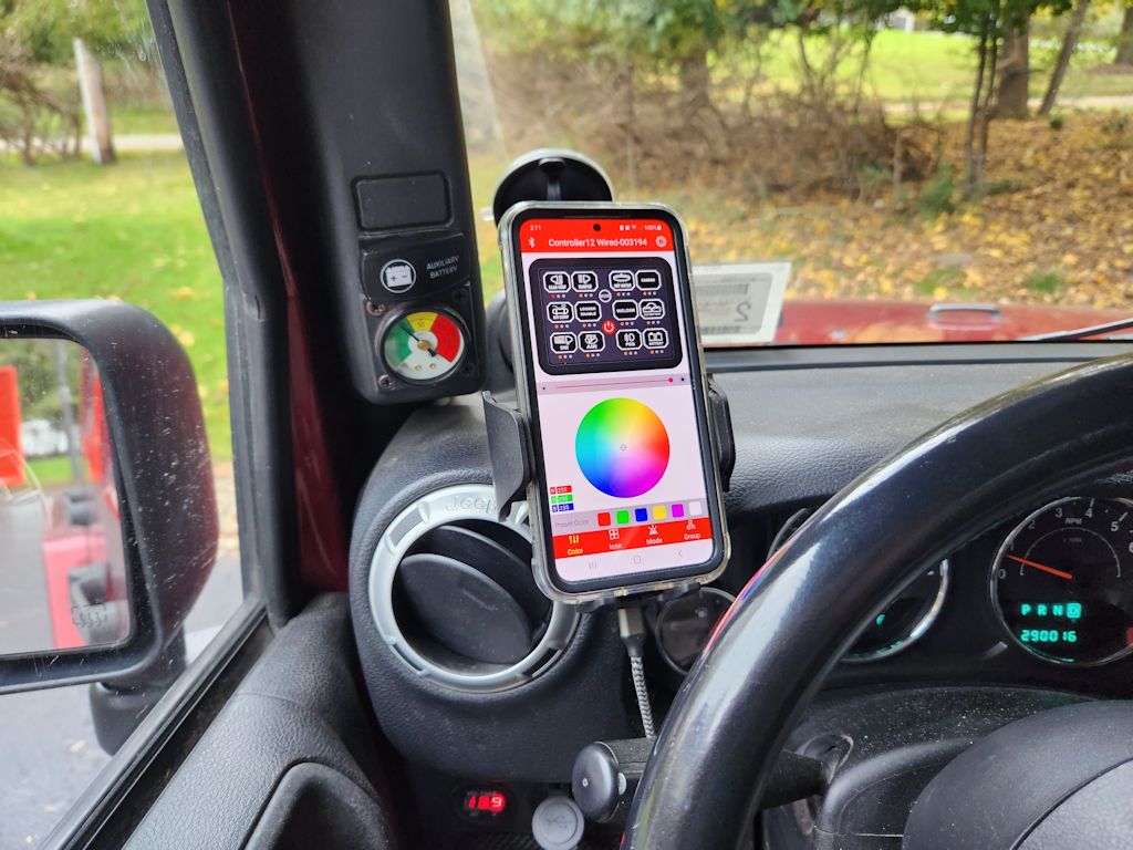
The other option is to use the Auxbeam Switch Panel app from your Android device or iPhone. The app is active in this next photo; the top half of the screen shows the 12 keys and you can configure the keytops on the screen with the same labels you might have put on the physical switch panel. And you can control the system anywhere within range of the Bluetooth connection.

AppInJK.jpg
 

jscherb

Expedition Leader
Part 4

Configuring the System

Once the system is installed and the accessories are connected, everything should be working – the accessories can be turned on or off with either the switch panel, the remote control or the smartphone app. I set everything up on the workbench to test the various switch configuration options - on/off, pulsed and momentary. In this video, switch 1 controls the light on the left in on/off mode, switch 5 controls the middle light in pulsed mode and switch 9 controls the light on the right in momentary mode.


The system can be configured either in the smartphone app or by using the keyboard.

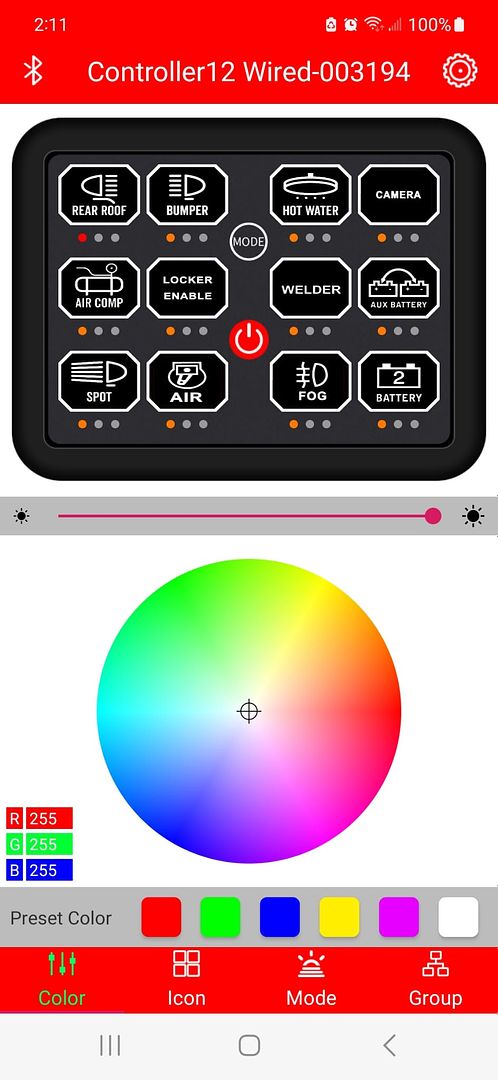
The default backlight color is green but an alternate color can either be chosen from several preset colors at the bottom of the screen or by using the color wheel. It’s not hard to set the backlight color to match the color of the backlight of most vehicle dashboards.

This screen can also be used to operate the switches by pressing the button on the screen, and if the phone is rotated, the keyboard will expand to fill the screen as seen in the video above.

AppBGColor.jpg


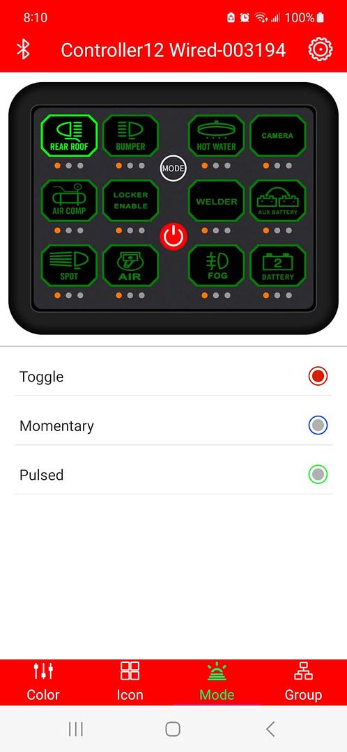
The Mode screen allows you to set the operating mode of the switch – there are three different ways the switch can operate:

  • On/Off. One press will turn the accessory on and a second press will turn the accessory off. This is the default.
  • Pulsed. One press will turn the accessory on, and it will pulse on and off. A second press will turn it off. This mode is useful for first responder emergency lights.
  • Momentary. The accessory will be turned on as long as the switch is pressed. When the switch is released, the accessory will turn off.

AppMode.jpg


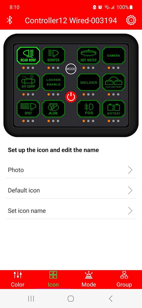
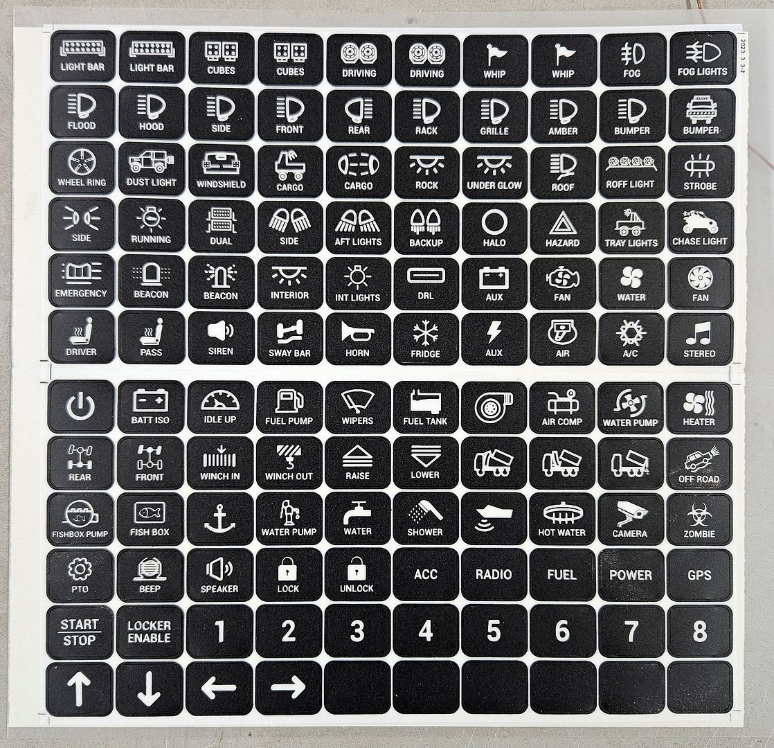
Over 120 stick-on labels are provided for the switch panel and labels can be set for the smartphone app as well. The Icon screen is where these are configured, and one can choose photos or default icons and the text can be set.

AppLabel.jpg


There’s one more screen for grouping accessories together, this enables multiple accessories to be operated from a single switch. For example, if you’ve got three lights, on circuits 1, 2 and 3, you can group switched 1, 2 and 3 so pressing one will turn on all three. Unfortunately this option wasn’t working in the Android version of the app when I tested it. I mentioned this to Auxbeam and they demonstrated it on their iPhone and promised to fix and update the app for Android.

The many switch labels provided with the product:

12GangLabels.jpg


If you need a label that's no provided, check out this link, in it you'll find out how to make your own labels: https://forum.expeditionportal.com/threads/barn-door-for-jk-factory-hardtops.127687/post-2942757
 

jscherb

Expedition Leader
Part 5

Are 12 circuits too many?

I tried to make a list of a dozen accessories that one might control with this system, and I kept running out of "driving" accessories and adding "overland/camping" accessories to the list. These would be things like campsite lights, a water pump for a shower, etc. I like to run those accessories from my auxiliary battery so I never take the chance of running down my starting battery in the wild but the way this system (and all the Auxbeam systems and many from other companies) is designed, all of the power to operate the accessories comes from one battery, presumably the starting battery. What I'd like to do is to be able to power the "driving" accessories from the starting battery/main vehicle electrical system and power the "overland/camping" accessories from the auxiliary battery.

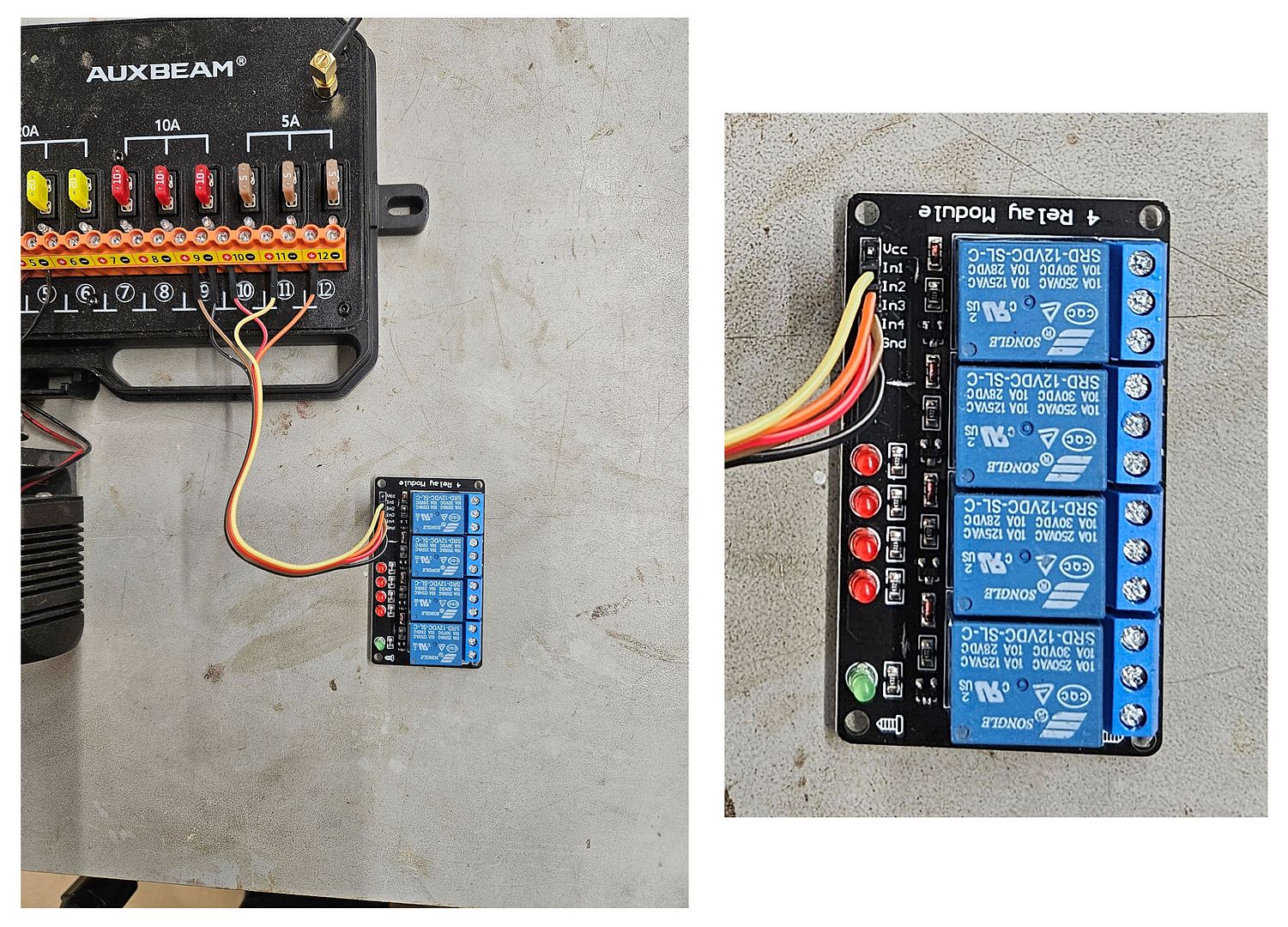
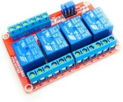
That turns out to be fairly simple with the addition of a relay board. In this next photo a 4-relay board is connected to the outputs 9-12 of the Auxbeam control box. Auxiliary battery power will go to one terminal of each relay, and an accessory will be powered by the output of the relays. The relays are rated at 10 amps, so almost all camping accessories can be powered that way - the most power hungry accessory I can think of is a fridge, and mine draws about 6 amps peak.

RelayBoard1.jpg


Relay boards are available with 1, 2, 4, 6 and 8 relays so it's possible to power many things from the auxiliary battery. You'll want a 12v relay board, and one that has a jumper to select to determine how the relays are activated - you want the jumper set to positive voltage rather than ground because the output of the Auxbeam control box will be positive voltage.

To finish up this option, the relay board should be mounted in a weather-resistant box, and the outputs of the relays should be fused to protect the relay board. The parts are readily available at places like eBay...

RelayBoard2.jpg
 

jscherb

Expedition Leader
Part 6

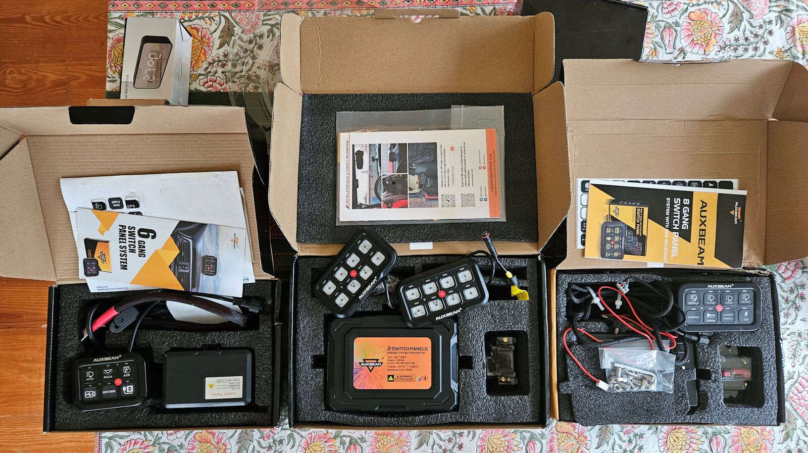
I've reviewed a number of other Auxbeam switch panels in the past few years, including their 6-gang, 8-gang, 8-gang with Bluetooth control, and the one the released just before this one, an 8-gang unit which includes dual switch panels.

OtherAuxbeamPanels.jpg


Reviews of some of the other panels:

8-gang dual panel: https://forum.expeditionportal.com/threads/barn-door-for-jk-factory-hardtops.127687/post-3104431

8-gang Bluetooth: https://forum.expeditionportal.com/threads/barn-door-for-jk-factory-hardtops.127687/post-2984630

6- and 8-gang compared: https://forum.expeditionportal.com/threads/barn-door-for-jk-factory-hardtops.127687/post-3043232

8-gang not Bluetooth: https://forum.expeditionportal.com/threads/review-auxbeam-8-switch-accessory-power-panel.206225/

6-gang (and custom labels): https://forum.expeditionportal.com/threads/barn-door-for-jk-factory-hardtops.127687/post-2942757
 

jscherb

Expedition Leader
Using Auxbeam Switch Panels with Dual Batteries in an Overland Vehicle

The Auxbeam line of switch panels make wiring and controlling electrical accessories easy – with one cable to a switch panel with 6, 8 or 12 circuits and one control box to connect the accessories to, installing and operating multiple electrical accessories in your vehicle couldn’t be much easier.

Not many vehicles have more electrical accessories than well-equipped overland/camping vehicles – in addition to accessories found on many vehicles such as driving lights, many overland vehicles have refrigerators, showers, campsite lights and more and the Auxbeam switch systems can really simplify the wiring in these vehicles.

The Auxbeam instructions call for connecting the system to a switched circuit in the vehicle so the system doesn’t draw power when the vehicle isn’t running, and connecting the accessory power directly to the vehicle’s starting battery. For most vehicles that’s the right way to do it, but what about using an Auxbeam switch system to control accessories to be used at the campsite when the vehicle isn’t running? You wouldn’t want to have to keep the ignition switch in the “on” position all the time while at the campsite, nor would you want to power the campsite accessories from the starting battery – either way you’re risking a dead battery when you try to start the vehicle to leave the campsite.

Many overland vehicles also have an auxiliary battery to power campsite accessories. Sometimes called a house battery or a kitchen battery, this battery is used to power accessories at the campsite so the vehicle’s main starting battery doesn’t get drained. The Auxbeam instructions only cover installation in vehicles with a single battery but with a few extra components it is possible to use an Auxbeam switch panel to control some accessories powered by the starting battery and other accessories powered by the auxiliary battery.

Configuring an Auxbeam system for a dual battery vehicle involves two steps:

1. Wiring the control box so it can be powered from a switched circuit when not at a campsite and powered from the auxiliary battery when camped.

2. Wiring the campsite accessories so they can be powered from the auxiliary battery but still be under the control of the Auxbeam system.

Powering the Auxbeam Control Box from a Switched Circuit or the Auxiliary Battery

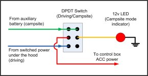
A way to use the switch system with the ignition switched off is to install a switch to control the power to the control box. In the "driving" position, the switch would power the control box from a switched circuit and in the "campsite" position, the switch would power the control box from the auxiliary battery. The benefit of this is that for normal driving, any accessories controlled by the system will be powered off when the vehicle is not running, so they can’t be left on accidentally and drain the battery. And at the camp site, accessories can be used without the need for the ignition switch to be on.

The benefit of using the switch system in "campsite mode" is that the vehicle circuits that are powered by the ignition switch being in the on position will not be powered, which eliminates some drain on the battery while sitting at the campsite. Typically, you wouldn't be using "driving accessories" at the campsite such as driving lights, you would only be using campsite accessories so powering the system from the auxiliary battery protects the starting battery.

But forgetting to turn off campsite mode when you no longer need it could cause your vehicle battery to discharge if you switch on “driving” accessories, so it’s a good idea to have a reminder that the campsite mode is on. This can be done with a double pole double throw (DPDT) switch and a 12v LED indicator light; wired as per the next diagram, the LED will light whenever campsite mode is on and will serve as a reminder to turn off campsite mode when it is no longer needed.

DrivingCampsiteSwitch.jpg

The current draw for the various Auxbeam switch panel systems varies by model, but they generally draw less than 1/10 amp. That's a negligible drain on the auxiliary battery just for the control box, but to that the drain of the accessories switched on must be added. For example, if an accessory that draws 5 amps is to be switched on, it’s best for that accessory to be powered from the auxiliary battery when the vehicle isn't running – that accessory, if left on long enough, it may drain the battery past the point of being able to start the vehicle the next morning.


Powering the Campsite Accessories

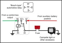
Powering an accessory from the auxiliary battery is accomplished with a relay:

RelayWiring.jpgb

The green wire is one of those routed from a circuit in the control box in the engine bay and it powers the relay when that circuit is switched on. The red wire goes to the positive terminal of the auxiliary battery, and through the relay the auxiliary battery powers the accessory, in this case a campsite light. One relay is required for each control box circuit that’s to be used with auxiliary battery powered accessories. The output of the relay should be fused as shown in the diagram above.

The relay in the diagram is a standard Bosch type automotive relay. These draw about 175ma. when activated, which isn’t much, but there are relays that draw about 20ma. when activated, and solid-state relays that draw 5ma., so if you’re really trying to minimize drain on the main battery, lower-power relays are available. But 175ma. isn’t much to worry about.

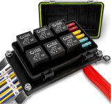
To make wiring simple, multi-relay boxes with fuses are available, such as this 6-relay unit that can be found on Amazon:


AmazonBoschRelay.jpg

Smaller relays with lower current draw are also available, such as this 4-relay board, also found on Amazon:


AmazonSmallRelays.jpg

These smaller relays may draw only 25 ma. or so compared to the larger Bosch relays that draw up to 175 ma. so if you're adding relays to a number of circuits these can save a bit of power but due to their smaller size and smaller connection points they’re a bit harder to use with larger gauge wire.

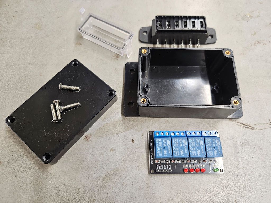
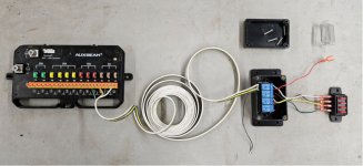
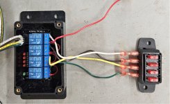
Here’s an example using one of the smaller relay boards. The relay board is mounted in a project box that was found on eBay and there’s an external fuse block, also found on eBay. The long coil of wire in this example allows the relays to be mounted in the rear of the vehicle, which is where the auxiliary battery is mounted in this particular vehicle. The wire is common 4-conductor trailer wire. The red wire hanging out of the box goes to the positive terminal of the auxiliary battery and in the close-up photo you can see how it's looped to all 4 relays. The black wire provides ground for operation of the relays. The campsite accessories connect to the right side of the fuse block.

RelayBoard3.jpg

RelayBoard4.jpg

Which Auxbeam Switch Panel to Use in an Overland Vehicle?

The wiring techniques described above can be used with any of the Auxbeam switch panels although some of the panels with more advanced features provide additional capabilities in an overland vehicle.


BC60, BA80 or any of the other single series panels.

The single series panels work just fine with the wiring described above, but having only one switch panel, all control of accessories will have to be from that single panel. At the campsite it may be a bit less convenient to have to use a switch panel near the driver’s seat to operate campsite accessories.


AR-600, AR-800 Bluetooth.

The switch panel systems with Bluetooth capability work very well in an overland vehicle – the smartphone app can be used to control the campsite accessories even while sitting around the campfire.

8GangInApp.jpg


Ra80x2 dual panel.

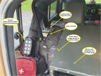
The RA80x2 system includes two switch panels; in the photo below the second panel is mounted to the roll bar in the back of the Jeep, next to the Trail Kitchen/fridge. This is a great place to operate the campsite accessories from.

RA80x2PanelInRear.jpg

The photo above also shows where the auxiliary battery is mounted, and if you refer back to the photo above of the small relay implementation the long coil of wire was used reach the relays, which are mounted in the back of the Jeep near the auxiliary battery. This Jeep also has solar charging for the batteries, which works fine with the wiring described in this article.


AC1200 with app and remote.

For a vehicle equipped with many overland accessories, such as a refrigerator, campsite lights, water pump for a sink, another water pump for a shower, an inverter to supply AC power, cabin lighting and more, the AC1200 with its 12 circuits is the ultimate system. It’s got both Bluetooth app capability as described above and a hardware remote, which is also perfect for sitting around the campfire.

12GangSwitchOptions.jpg
 

jscherb

Expedition Leader
I received an email overnight from Auxbeam. In it they said their engineers have "been adjusting the bracket (length, space, etc.) based on your suggestions. When the adjustment is completed, we hope to send it to you." This applies to the JK and JL Wranglers; the bracket that came with the kit works fine in the TJ as I showed above. When they send me the updated bracket I'll verify that it works in the JK and JL and still works well in the TJ. So they continue to be responsive to input and feedback about their products.

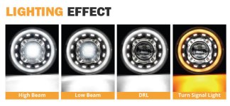
Also they said they're sending me a set of new 7" LED headlights (not released yet). I don't know the specs on them yet because they're not on the Auxbeam web site, but the email included the installation instructions which I'll review and send them corrections/suggestions while I'm waiting for the headlights. If there's interest I'll post a review of the headlights when they arrive but since they're not really overlanding items I'll only post a review if people tell me they're interested.

LightingEffect.jpg

And also in this morning's email was a message from a battery/solar company which said they have "developed a 12V 100Ah LiFePO4 battery with an LCD display and built-in BMS." (Battery Management System). They offered to send me a sample to test and review. I'm always interested in ways to improve the electrical systems in my overland Jeeps, so I'll probably take them up on the offer.
 

Ozarker

Well-known member
Waaaaay tooooo much work to turn on gadgets and lights.

You have more switching options than a UH-1 chopper.
 
  • Like
Reactions: plh

jscherb

Expedition Leader
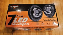
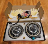
These arrived yesterday from Auxbeam. LED headlights with DRLs and turn signal halos. The package includes two headlights, adapters for H4-H13 plugs (that's for a JK, the plug on the headlight is a standard 3-pin sealed beam plug which will fit a TJ), wire and suitcase connectors to connect the DRLs and turn signal halos, instructions, a large Auxbeam decal and glove with rubber grips (so you don't drop the lights? Nice touch).

StarlightHeadlightsBox.jpg

StarlightHeadlightsContents.jpg

They sent them to me to test and review so I'll probably test them in both my '06 pickup and my JKU although they're not the style I want for either Jeep so after testing I'll remove them and see if I can find a more permanent home for them.

Unless someone tells me they are interested in this type of light, I won't post any more about them here; they're not really the type of thing one puts on a real expedition Jeep, they're more of a mall crawler thing.
 
Last edited:

Zeep

Adventurer
I agree that they look rather "Blingy" then some of the other options, that are available.
 

jscherb

Expedition Leader
I agree that they look rather "Blingy" then some of the other options, that are available.
Definitely not what most expedition vehicle owners would want, but it's fun to test things like this even if they're not for my Jeeps. I have a great relationship with Auxbeam and when they do have something I want for one of my Jeeps, they'll be very happy to send me a sample to test, review (and use in my Jeep), so when they ask me to test something like his I'm only too happy to oblige. And I'll post a review over on a forum that has more bling enthusiasts, this morning I did the same post over there and one response was:

Those headlights look nice. Looking forward to your install and opinions of them.

Different forums for different interests :). BTW people on that forum are enthusiastic owners of the MORryde tailgate reinforcement, which is why I got involved over there - to answer questions people might have about the use of my design.
 

jscherb

Expedition Leader
I'm interested in your review of them. Do you know the price point yet?
I don't know what the price will be; they're not released yet and I didn't ask about the price. If I find out what the price is I'll include it in any reviews I post.

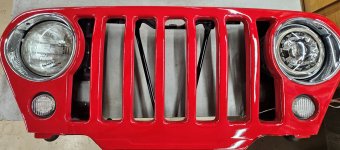
So far all I've had time to do is install one in a custom TJ grille I've got in the workshop and light it up to test the basic functions and compare it to a factory sealed beam. I'm impressed so far, all of the functions work as documented and the headlight seems very bright, but I'll have to install them in a Jeep and do some night driving to give them a real test. I hope to get to that in the next few days.

StarlightInGrille.jpg
 

Forum statistics

Threads
188,019
Messages
2,901,216
Members
229,411
Latest member
IvaBru
Top