Review: Auxbeam slim switch panel systems

jscherb

Expedition Leader
Auxbeam Slim Switch Panel Systems
AS-400, AS-600 and AS-800

Auxbeam has been a major player in the switch panel market for quite a while and has a range of 6- 8- and 12-gang panels, some of which include Bluetooth and remote controls. They recently released a new series with slim-line panels, which may be easier to fit in many vehicles. This article will review their AS-400 (4-switch) and AS-600 (6-switch) units. They also offer an 8-switch unit.
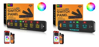
AS400andAS600.jpg
I've done reviews of a number of Auxbeam switch panels over the past few years and since these new slim-line units have much in common with their other panels, this article will mostly focus on the features of these new units; much more detail about implementing Auxbeam panels in a variety of Jeeps and different configurations can be found in the links at the bottom of this article.

Typical of all Auxbeam products, the components are well packed in foam in the box. This is what you get with the AS-400 4-switch panel (the AS-600 and AS-800 are very similar):
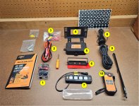
4-GangComponents.jpg

Components include:

1. 60-amp circuit breaker
2. Heavy-gauge main power cable
3. Fuse tap to turn the system on with switched power from the vehicle
4. Mounting bracket for the control unit
5. The control unit
6. Mounting bracket and double-sided tape for the switch panel
7. Switch panel and weatherproof cover
8. Antenna for the wireless remote control
9. Long wire to connect the switch panel inside the vehicle to the control unit, which is typically mounted not far from the battery
10. Wireless remote control

Items not numbered include a bag of hardware, spare fuses and a spare battery for the remote, a screwdriver, some zip ties and at the top right of the photo – labels for the switches.

The instructions are excellent, well-illustrated and provide step-by-step guidance for installation and setup. A few sample pages of from the instruction book:
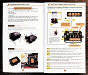
Instructions.jpg

The control unit includes connections for main power and ground, power and ground connections for 4 accessory circuits, connectors for the switch panel and switched accessory power (to turn the entire system on/off with the ignition) and a connector for an antenna wire for the remote control. There's a fuse for each accessory circuit, and a nice feature, common to most Auxbeam units, are LED's which will light if a fuse is blown, simplifying the task of finding and replacing a blown fuse (the LEDs are between the fuses and the orange circuit connector strip and not visible in the angle of this photo). The AS-600 and AD-800 control units are similar, but slightly larger with 6 and 8 fuses/circuits each. The 4- and 6-switch panels:
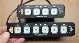
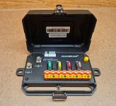
SwitchPanels4and6.jpg
4-GangControlBox.jpg

More to come...
 

jscherb

Expedition Leader
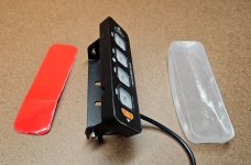
The switch panel can be mounted to a flat surface using double-sided tape and there's also an adjustable mounting bracket for it for places where direct mounting might not work. The bracket can either be attached with screws or it can also be attached with the supplied double-sided tape. Also shown in this next photo is a soft plastic switch panel cover, very useful if the panel is installed in an open vehicle and subject to the elements.

4-GangSwitchPanelMounting.jpg

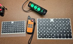
Auxbeam provides 60 different labels for the keys in two sizes. The large ones fit on the switch panel and the small ones fit on the remote control, the “Roof” label is on both the switch panel and the remote:

SwitchLabels.jpg


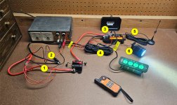
The wiring is mocked up on the workbench in this next photo.

4-GangWiringMockup.jpg

The wiring in the above photo may look a little jumbled, but it’s actually pretty simple.

1. The heavy-gauge red (positive) wire is connected from the battery (in this case it is the bench power supply with a clip lead) to the circuit breaker. The second heavy-gauge red wire connects from the other side of the circuit breaker to the positive terminal in the control box.
2. The heavy-gauge black wire (negative) is connected from the battery (in this photo to the power supply with a clip lead) to the negative terminal in the control box
3. The thin red wire plugs into the ACC connector in the control box and runs (in this example) to the positive terminal of the power supply. In a vehicle it would run to a switched circuit in the vehicle’s fuse box and be connected with a fuse tap. The vehicle’s switched circuit would turn on the switch panel system with the vehicle’s ignition is turned on.
4. The long wire with the black braided cover connects from the “4 Pin Connector” to the switch panel. It’s long enough that it should be able to reach from the engine compartment to somewhere convenient to the driver in most vehicles.
5. The antenna for the remote control (if the remote control is to be used) is connected to its terminal in the control box.
6. In this example, a small LED is connected to circuit 4 of the control box; you can see that the LED above switch 4 on the switch panel is lighted, which means that this circuit is turned on and of course the LED is lighted by that circuit.


Each switch can be configured to be on/off, momentary or pulsed;

- On/Off. One press will turn the accessory on and a second press will turn the accessory off. This is the default.
- Pulsed. One press will turn the accessory on, and it will pulse on and off. A second press will turn it off. This mode is useful for first responder emergency lights.
- Momentary. The accessory will be turned on as long as the switch is pressed. When the switch is released, the accessory will turn off.

Setting the mode of the switches is very simple – press the “Mode” button twice, and then press the switch you want to change the mode of – when the LED above that switch is red, the switch will be in On/Off mode. Green is Momentary and Blue is pulsed. The mode of multiple switches can be changed at the same time and when done setting modes, press the Mode button once more to record these modes.


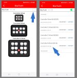
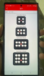
I downloaded the latest version of the Auxbeam switch panel app to test operation from my phone and the slim 4-gang panel is supported but it isn’t obvious. When you tap the Bluetooth icon you’re asked to select a 6, 8 or 12-circuit controller. To choose the 4-circuit controller, tap the slider in the upper right corner of the screen (indicated by the blue arrow) and select the 4-circuit controller from the list as shown below. Auxbeam tells me the app will be updated shortly to show a 4-circuit controller on the first Bluetooth screen.

BluetoothSelection.jpg


The app gives you control of the backlight color and can also be used as a remote to control switch operation, among other functions. Since the same app works for all of the Auxbeam Bluetooth switch panel systems, more information on the app can be found in the reviews linked at the bottom of this article.


Bench testing the system with several LED's:


More to come...
 

jscherb

Expedition Leader
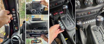
The slim size of these switch panels provides a lot more opportunity for mounting in a typical Wrangler. These are some of the places the 4- and 6-gang panels would fit nicely in a TJ:b

TJSwitchPanelLocations.jpg

A few possible mounting locations in the JK:

JKSwitchPanelLocations.jpg


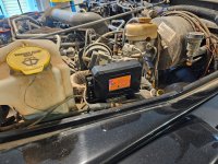
A mounting bracket is provided for the control unit, and it commonly would be used to mount the unit to an inner fender. The control box is typically mounted in the engine compartment. In the TJ, the mounting bracket and control unit fit nicely on the drivers side inner fender:

TJMounting.jpg

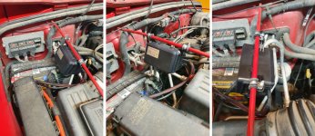
The one problem with that location is that the heavy-gauge power cables supplied with the kit are too short to reach the battery if the control box is mounted there. But Auxbeam does offer much longer cables for those who might need them: https://auxbeam.com/collections/wir...0-7awg-with-6m-and-8m-tinned-copper-wire-lugs, but I like to mount the control box to the grille support rod using wire clamps. This photo is from the earlier review of the 6-gang system; mounting the control box for these slim systems could be done in the same way and the heavy-gauge power cables will reach the battery easily. There’s a link to that review at the end of this article.

TJMounting.jpg


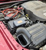
The later model Wranglers don’t really have enough free inner fender real estate to use the supplied mounting bracket, but one place it could be mounted in a JK is to the lid of the factory fuse box. If you do mount it there make sure there’s enough slack in the wires to allow the factory fuse box to be opened, and note in the photo that the control box is slightly over the edge of the fuse box lid – that’s to allow the wires to the control box to exit from the slots in the bottom of the control box housing.

JKFuseBoxTop.jpg

One last thing I tried on the bench – can the switch panels be mixed with different control units? Maybe you’ve got an 8-gang with the rectangular panel and the new slim panel would suit your interior better but you don’t want to rewire all of the accessories? Or what if you’ve got the RA80 X2 unit and you want to use a slim panel on the dash but a rectangular panel in the back near your fridge and other camping accessories? I bench tested and RA80 X2 control unit with a rectangular8-gang switch panel and a slim 4-gang and everything works just as it should.


Auxbeam did tell me ahead of time: “all of our RGB switch panels with 4-pin connectors are compatible with one another” so if you’ve got any of their earlier RGB systems, you can mix switch panels just by plugging them in.


I’ve always been impressed with the Auxbeam switch panel systems and I think they’ve hit a home run with these new slim units. They fit in so many more places in many vehicles it seems like they’ll be a hit.


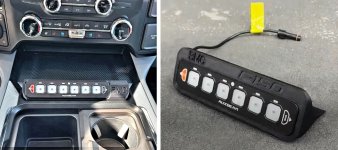
And this just in… apparently Ford aftermarket company BMC Lights thinks they’ll be a hit too – they’re now promoting a custom mount for Ford trucks to fit the 6-gang slim panel. Maybe other companies will join the party and make custom mounts for Jeeps for these new panels:


BMCfordMounts.jpg

Reviews of other Auxbeam switch panel systems for more information on those systems, wiring in general, mounting and more about the app:

https://www.expeditionportal.com/fo...factory-hardtops.127687/page-331#post-2984630

https://www.expeditionportal.com/fo...factory-hardtops.127687/page-327#post-2963491

https://www.expeditionportal.com/fo...factory-hardtops.127687/page-322#post-2942757

https://www.expeditionportal.com/fo...factory-hardtops.127687/page-322#post-2940341

https://www.expeditionportal.com/fo...ch-accessory-power-panel.206225/#post-2640852

https://wranglertjforum.com/threads...ircuit-switch-panel.58281/page-2#post-1034515

There is also review on the dual switch panel unit and the focus of that article is using the dual panel system in an overland/camping vehicle: https://forum.expeditionportal.com/threads/barn-door-for-jk-factory-hardtops.127687/post-3104431


jscherb

Expedition Leader
Auxbeam sent me an update on compatibility between switch panels and control units and about the app.

They’ve updated the app to show a 4-switch panel on the Bluetooth screen so you don’t have to go to the detailed Bluetooth list to pick the 4-switch system. They said:

The different versions of our app are compatible across all systems [that have Bluetooth capability]. The APP pictures have been updated with 4 channels.

AppUpdate1.jpg

And they said this about compatibility of switch panels and control units:

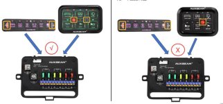
Our RGB panels come in two versions. The older version does not have a mode button (it only has a single button), while the upgraded version includes a mode button (dual buttons). Only the dual-button version allows interchangeable use of panels without requiring rewiring or replacing the control box. Unfortunately, the older single-button version does not support this functionality.

They included this image:

PanelCompatibilityUpdate.jpg

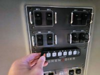
And slightly off-topic... someone on the the Grenadier Owners USA group on Facebook asked about the Auxbeam panels so I responded with a detailed answer to their question. One option for the Grenadier is called the "High Load Switch Panel", which provides additional user circuits for accessories. My new Grenadier has this option so I doubt I'll need an Auxbeam system in that vehicle but I took this photo of the overhead panel in the Grenadier - the Auxbeam switches could be mounted overhead as shown; above the Auxbeam switches in this photo you can see the extra circuits provided by the High Load Switch Panel option, including a 500-amp circuit for winches and such.

GrenadierSwitchPanel.jpg

(Sorry for getting off the Jeep topic; I posted that in case someone reading has a Grenadier without the High Load Switch Panel option and needs more circuits)
 
Last edited:

Forum statistics

Threads
188,208
Messages
2,903,801
Members
229,665
Latest member
SANelson
Top