Second Alternator Charging Lithium Battery Bank

mechengrsteve

Most time adventurer
Balmar MC-614 has current limiting built in, to protect the alt from burning up

and also a small LFP bank from being charged to fast

in fact much more adjustability than Sterlings

great flexibility for changing conditions.

Unfortunately not an option foe modern vehicles where the alt is tied into the vehicle computer
Balmar regulators are 'charging regulators' and never intended to operate on a vehicle/engine system. Separating a second alternator from ECU control is definitely something that can be done and a charging regulator installed. All that is needed to operate a second alternator as a dedicated house battery charger is to replace/bypass the regulator and connect the alternator output directly to the house bank (warranty may be a consideration), making two separate systems. There are/may be some jumpers needing to be installed on the vehicle side of the regulator harness to prevent the ECU from seeing an alternator fault but that is minor.

Some issues to consider; 1) A Balmar 'charging regulator' (I've got a MC-624 sitting right in front of me) cannot be on your primary alternator regulator because it puts out a voltage based on what a battery should need while charging, not what your vehicle should need when operating. 2) Balmar temperature regulation only kicks in when the alternator reaches or approaches its limit (not defined in Balmar docs) and then, initially 'reduces field voltage to 50%'. This drops charging considerably but it still has no way to know output since it does not measure current. 3) I have been in situations where dangerous charging could not be prevented by a Balmar charging regulator (which is why it is sitting on my desk and not in my truck). Here's the scenario; If you deplete the (large) LFP house battery and the next morning, kick your engine on, the regulator will charge like CRAZY while the alternator quickly heats up. My first 120A OEM ford 3G 120A alternator would hit 150A immediately (I now have a 220A). The bottom line is, parts of your system cannot tolerate that load and the Balrmar regulator responds too slowly to protect your entire system. Firstly your diodes will overheat very rapidly (in single or double-digit seconds). Secondly, you had better have cabling ready to handle this surge that there is no way to know. The alternator lead has low thermal mass and will heat up far faster than the alternator will. It may take 10-15 minutes for the alternator to heat up but the wire will reach max temperature in a minute or two. 4) If you don't know, alternators are 'rated' at 6000 (alternator) RPM into an industry-standard resistor load bank. The resistor bank has a lower resistance than a lead-acid battery intentionally so it can/will accept a large test current. This is mostly why you will never see amperage out of a high cap alternator into a vehicle with LA starting battery approaching its rating. However, the resistance of a fully discharged/low SOC lithium battery bank has far less resistance than that resistor bank and WILL allow huge currents, well in excess of even the peak alternator rating. Also recall, that an alternators rating is a 'peak' rating, not a sustained rating. The peak rating is measured under a very specific test bench condition that does not apply when in a vehicle. It is only helpful in comparing alternators to each other. Alternator manufacturers do not provide amp vs duty cycle ratings because it is highly dependent on underhood temperatures and airflow, neither of which they can control or predict. 5) Balmar does have an 'Amp manager' setting with which you can specify a lower maximum field output (in percentage). This permanently reduces the output of your alternator under ALL conditions. The regulator does not know the capacity of the alternator it is connected to so there is no way to know how this affects alternator output unless you experimentally measure the output into a discharged LFP bank, and then tweak the Amp Manager setting to your limit. Remember, it does not measure or limit amperage, it is only controlling field voltage. If you don't set it correctly or if something in the system changes, the amperage could be destructive.

I find that there are too many variables in alternator direct lithium charging system for these 'advanced' but still relatively crude regulators (Wakespeed being a possible exception) to be 'automatic' and reliable. I have a semi-automatic system (with thermal cutoff fail-safe) that shows me the amperage, voltage and temperature of the alternator on my console along with a finely adjustable field control that allows me to set the upper limit on charging, every time I turn it on. Because, every time I turn it on, the batteries are at a different SOC. My message is; while advanced 'charging' regulators are good, they were designed for a lead-acid market and migrated with minimal improvement into a lithium environment. They are still really not advanced enough to be fully reliable.
 

mechengrsteve

Most time adventurer
The large frame alts designed for emergency vehicles will run at rated output in hot conditiins continuously.

Leece-Neville is a good brand

also surplus military stuff, some Hummer units can put out like 13+ kW

Alternatively, a VR that derates the current output based on temperature sensing

But obviously such extreme mods can cost as much as some spend on their whole truck
I beg to differ; Alternators are not rated to produce their output continuously and in practice, can only produce about half their rating continuously. Ratings are created to identify a relative capacity in test bench conditions, not in an engine compartment. In a nutshell; test conditions are when connected to a fixed resistance load bank at 6000 RPM in a 23C environment.

In ISO 8854:2012, alternator testing and labeling standards indicate that the “rated output” of an alternator is the amount of current that it is capable of producing at 6,000 RPM. Each standard also indicates a range of other speeds that an alternator needs to be tested at and defines “idle output” and “maximum” output in addition to “rated output.” Although alternator manufacturers, rebuilders, and suppliers typically refer to the rated output in promotional materials, both the ISO and the SAE require a format of “IL / IRA VTV,” where IL is the low, or idle, amperage output, IR is the rated amperage output, and VT is the test voltage. This results in ratings that look like “50/120A 13.5V,” which are typically printed or stamped on the housing of an alternator.

All this means is that alternator 'ratings' are specifically one data point on a range of possible outputs. All alternator outputs will have limitations based on the operating environment. Theoretically, if you could provide enough cooling, an alternator could operate at virtually any output. In reality, underhood temperatures are high, and cooling airflow is relatively slow because of all of the confined equipment. Brands can have some effect on this, most still have a CD capacity of around half their rating. I have several Neihoff 400A/28V MRAP alternators (HMMWV alternators only get to ~200A because of space constraints) that may one day go on my M10881 5 ton (which has a 200A)...they are beasts and they can produce ~250A @ 28.8V continuously (7.2kw). They do make them as big as 500A rated as well. These large military alternators were specifically created during the Iraq war to power thermal decoys (rectangular heaters on a pole ~15' in front of a vehicle) that emulate engine heat to pre-detonate thermally fused off-route explosives. Yes, I am a mechanical engineer and former combat engineer.....


The
 

mechengrsteve

Most time adventurer
The OP asked about a dedicated alternator for a large lithium battery bank. Winnebago and Coachmen are both offering this kind of system for their rv's without generators. They use either a Nations or Balmar high output alternator and a Balmar 614 standalone regulator. But those offerings are hardwired and never disconnected like a truck camper. I have asked both companies what device they use to limit the secondary alternator output but I have never gotten a straight answer other than Coachmen stating that they don't use a B2B charger in their Li3 rv's. I wouldn't want any alternator to run at more than 50% of max. I also don't know how such a system should be designed to accommodate disconnecting the camper. And there's this article...https://www.truckcamperadventure.com/ditching-the-generator-for-the-alternator/.
Thanks for the upvote...I wrote that article...
 

john61ct

Adventurer
There are many alternators, large frame heavy duty designed for emergency vehicles, military, industrial use

that are in fact perfectly capable of putting out their full rated current 24*7

Yes the VR or DC-DC chargers are needed when used to charge a LI bank
 

mechengrsteve

Most time adventurer
It is also not entirely clear how a B2B charger would protect against a BMS shutdown (aka a 'load dump')?

The issue here is not so much that you will damage the alternator, but that when you suddenly disconnect a large load from the alternator, the output voltage of the alternator will spike due to the inductance in the field windings. It is primarily other things attached to the same circuit (eg ECUs, accessories, maybe the B2B itself) that would be damaged. If the battery were to suddenly disconnect from the B2B, the load at the input to the B2B will also suddenly drop - leading to the same situation. Littlefuse has a couple of good application note on this, and how to protect against it.
A couple of thoughts on load dump.
1) B2B chargers, like any other battery charger, charge in stages. The full charger current of a B2B (assume 40A) is during the CC phase and is finished at ~85%SOC (~14V), from there, saturation/CV tapers current to ~10% or 4A at end of charge. Assuming the BMS was to shut off @ Vmax ('over voltage' is 14.6V), it would happen about the same time/current as the B2B would have terminated anyway. In this situation, there is no 'load dump' that occurs even if charging is terminated by the BMS. A 4A change in the vehicle circuit would be smaller than many others (heater blower and headlights are 6-8A). TBL, there is no increased risk of a load dump by using a B2B even it was to force the BMS to shut off.
2) ANY charger feeding a BMS-controlled battery should be programmed to terminate the charge at LESS than Vmax. You never want to use the BMS to be the control mechanism for external equipment. It's not good for the system operation or the equipment. Remember, the BMS is sensing cell group voltages and will cut off when any cell group reaches 3.65V, even if the battery max of 14.6 is not reached. The faster you charge, the more likely cells will be out of balance. This virtually guarantees that the battery will never reach 14.6V because it is virtually impossible for all cell groups to reach 3.65 simultaneously. Good practice is to terminate charge ~14.5-14.55 at the most. And again, terminating the charge by shutting off the charger or the BMS shutting off is about the same, low amp change.
3) The most likely thing to cause a load dump is improperly sized or located overcurrent protection device (OCPD). You will notice that automotive manufacturers rarely place OCPD on the alternator cable for this very reason. If they do, its a fusible link. The destructive potential of lithium batteries suggests that OCPD is prudent. ABYC specifies it must be within 7" of the battery (house battery). Key to its proper use, it should be sized for fault, not overload. This means it should be larger than the maximum possible current the alternator can deliver (which may be well above it's rated capacity if connected to a low SOC lithium battery). The only thing that should be able to cause it to function is a short, in which case, the resulting load dump will most certainly destroy the alternator which would certainly be a better outcome than the fire that would result from not having OCPD.
4) There should be no OCPD between the alternator and the B2B. Neither is a source of stored energy (thereby not requiring OCPD).
5) There is frequently a TVS (Transient Voltage Suppressor, a Zener diode that grounds voltages above ~30V) in the diode bridge of better alternators, particularly variable voltage types. I don't know when this started, but I' relatively confident it is pretty common, particularly in OEM and quality aftermarket alternators. I believe this is intended to protect engine electronics (and other downstream devices) if there were a load dump but it is likely not to protect the regulator. Sterling makes an aftermarket add-on that does the same thing. I think this may be a case of selling you something that you don't know you already have.
6) Due to the use of variable voltage alternators which increase the voltage seen in vehicle circuits, power supplies in vehicle electronics built in the last 5+ years are built to tolerate a higher range of input voltage. This is not to say they are hard enough to resist a load dump but the implication is they are 'better'.
7) The B2B, being essentially a microcontroller-managed, big DC-DC converter, is packed with large capacitors and inductors used to perform the boost conversion. These devices act as an electronic 'fly wheel' to damp a wide variety of voltage variations. They are also designed to accept a pretty wide range of input voltage, both above and below their output voltage so I very much doubt they would be harmed by a spike coming from the alternator, particularly when it is also damped by the starting battery. They may even contribute to damping spikes put out by the alternator but that is a guess.
 

mechengrsteve

Most time adventurer
It is also not entirely clear how a B2B charger would protect against a BMS shutdown (aka a 'load dump')?

The issue here is not so much that you will damage the alternator, but that when you suddenly disconnect a large load from the alternator, the output voltage of the alternator will spike due to the inductance in the field windings. It is primarily other things attached to the same circuit (eg ECUs, accessories, maybe the B2B itself) that would be damaged. If the battery were to suddenly disconnect from the B2B, the load at the input to the B2B will also suddenly drop - leading to the same situation. Littlefuse has a couple of good application note on this, and how to protect against it.
A couple of thoughts on load dump.
1) B2B chargers, like any other battery charger, charge in stages. The full charger current of a B2B (assume 40A) is during the CC phase and is finished at ~85%SOC (~14V), from there, saturation/CV tapers current to ~10% or 4A at end of charge. Assuming the BMS was to shut off @ Vmax ('over voltage' is 14.6V), it would happen about the same time/current as the B2B would have terminated anyway. In this situation, there is no 'load dump' that occurs even if charging is terminated by the BMS. A 4A change in the vehicle circuit would be smaller than many others (heater blower and headlights are 6-8A). TBL, there is no increased risk of a load dump by using a B2B even it was to force the BMS to shut off.
2) ANY charger feeding a BMS-controlled battery should be programmed to terminate the charge at LESS than Vmax. You never want to use the BMS to be the control mechanism for external equipment. It's not good for the system operation or the equipment. Remember, the BMS is sensing cell group voltages and will cut off when any cell group reaches 3.65V, even if the battery max of 14.6 is not reached. The faster you charge, the more likely cells will be out of balance. This virtually guarantees that the battery will never reach 14.6V because it is virtually impossible for all cell groups to reach 3.65 simultaneously. Good practice is to terminate charge ~14.5-14.55 at the most. And again, terminating the charge by shutting off the charger or the BMS shutting off is about the same, low amp change.
3) The most likely thing to cause a load dump is improperly sized or located overcurrent protection device (OCPD). You will notice that automotive manufacturers rarely place OCPD on the alternator cable for this very reason. If they do, its a fusible link. The destructive potential of lithium batteries suggests that OCPD is prudent. ABYC specifies it must be within 7" of the battery (house battery). Key to its proper use, it should be sized for fault, not overload. This means it should be larger than the maximum possible current the alternator can deliver (which may be well above it's rated capacity if connected to a low SOC lithium battery). The only thing that should be able to cause it to function is a short, in which case, the resulting load dump will most certainly destroy the alternator which would certainly be a better outcome than the fire that would result from not having OCPD.
4) There should be no OCPD between the alternator and the B2B. Neither is a source of stored energy (thereby not requiring OCPD).
5) There is frequently a TVS (Transient Voltage Suppressor, a Zener diode that grounds voltages above ~30V) in the diode bridge of better alternators, particularly variable voltage types. I don't know when this started, but I' relatively confident it is pretty common, particularly in OEM and quality aftermarket alternators. I believe this is intended to protect engine electronics (and other downstream devices) if there were a load dump but it is likely not to protect the regulator. Sterling makes an aftermarket add-on that does the same thing. I think this may be a case of selling you something that you don't know you already have.
6) Due to the use of variable voltage alternators which increase the voltage seen in vehicle circuits, power supplies in vehicle electronics built in the last 5+ years are built to tolerate a higher range of input voltage. This is not to say they are hard enough to resist a load dump but the implication is they are 'better'.
7) The B2B, being essentially a microcontroller operated a big DC-DC converter, is packed with large capacitors and inductors used to perform the boost conversion. These devices act as an electronic 'fly wheel' to damp a wide variety of voltage variations. They are also designed to accept a pretty wide range of input voltage, both above and below their output voltage so I very much doubt they would be harmed by a spike coming from the alternator, particularly when it is also damped by the starting battery. They may even contribute to damping spikes put out by the alternator but that is a guess.
Fwiw,
Aircraft alternators frequently use forced air cooling. Air is provided thru a ductwork or hose.
I wont be surprised if some marine alternators are the same.
Sounds like a perfect thing for overkill happy ExPo Guys.
They also make oil cooled alternators on transport busses, mostly because rear engined vehicles have side mounted radiators. Airflow drawn from the side and exhausted out the back/bottom does not circulate over the engine and 'underhood temperatures' are pretty high.

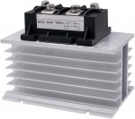
I'm hoping not to add more moving parts......Annother improvement to cooling an alternator is to install remote diodes. There are some aftermarked manufactures who make them but 3 phase bridge rectifiers are a very available commodity product. I have two thoughts. 1) ADDING a second diode bridge outside the alternator can share the load wtih internal diodes and reduce the heat load inside the alternator. 2) I think it would be a far better idea to REPLACE the interior diodes with an exterior bridge to completely remove the diode heat contribution but even more, to remove the air restriction the diode bridge creates. I'd love for the existing internal fan to just get more breathing space. I'm working on doing this to my 220A 3G alternator because it is mounted immediately in front of the passenger side head and with the engine running at 220-230F about 1/2" from the diode bridge. It has very little (no) 'breathing room'. My OEM 120A alternator would only run ~60A continuous duty at 120C (a relatively low alternator temp) . My 220A runs about 85-90A CD. The 120A demostrated that it runs at half rated continuously (typical) but the 220A is less than half. I think it is because of the terrible airflow. I may also attempt to add some form of air induction but don't think I have space to actually duct it through the alternator. I have bought a 200A, 3 phase diode bridge ($30 and ~4" l x 3" w x 1.5" h) and some 8AWG, 200C ($20, slicone insulated) wire. I am also expecting to buy a sizeable aluminum heatsink to bolt it to and hopefully mount it in the fan shroud somewhere to use cooler air and not have to privide my own fan. This also opens the opportunity to add TVS diodes in more plentiful numbers to reduce the potential effects of a load dump.
 

Attachments

  • 3Phase200Arectifier.jpg
    3Phase200Arectifier.jpg
    90.4 KB · Views: 7
  • 200AbridgeRectifierWheatsink.jpg
    200AbridgeRectifierWheatsink.jpg
    72.8 KB · Views: 7

john61ct

Adventurer
A cheap lead batt tied directly inline with alt output will buffer load dumps.

This can be Starter batt if course.
 
We had a dedicated 250A large frame DC Power Solutions alternator on our sailboat that charged a 540ah LiFePO4 bank that was regulated by a Balmar 612 regulator. We had the field wire on a switch to turn on or off the alternator when the engine was running. The alternator would charge the battery at 210-220a when we needed to recharge. It did this dutifully for over two years of cruising until we sold it and it's still going. If we got the optional external diodes, we probably could have charged at higher amps with no issues. We had the temp control on the alternator to protect the alt. We set the temp to a safe Level and all was well. We charged our bank at CV of 13.8v and cut the alternator when the amps started dropping to around 20a. At that point we had a full battery and there was no need to continue charging. We used a victron battery monitor to see volts, amps, and soc.

If you have a duel alt system for a camper battery, you can put the field wire on a switch so whenever the camper isn't in the truck you leave it off and the alt will just spin freely. Set your voltage regulator up to whatever the battery manufacturer recommends(Battleborn in this case), set the other parameters like temp, alternator derating (used to be called belt saver), and be done. If there is a wire from the BB BMS to shut off the alternator, set it up to cut the alternator field wire(brown typically) and you won't need a load dump or resistor.

Don't forget to upgrade and size your wires and fuse for Max alt amps. The stock wires are not going to be ready for all that juice. We used ANL fuses for most of our stuff. We had a big 350a Tfuse for the main fuse to the pack.

Sent from my Pixel 5 using Tapatalk
 

carterd

Active member
If one wanted a dedicated alternator charging a Li battery with off-the-shelf components what would you think of this setup?

  • Externally regulated alternator, ideally with published specs on output vs. RPM vs. temperature and with specs on continuous duty cycle. Sized appropriately for the recommended charging current of your battery bank.
  • Sterling Power Alternator Protection Device to protect alternator against spikes
  • Shunt to measure current flowing from alternator to battery
  • Wakespeed WS500 regulator. Key advantages to this regulator:
    • Alternator temperature sensing
    • Battery temperature sensing
    • Current sensing (via shunt)
    • Multiple charging profiles for various battery types
    • CAN bus compatible
    • Generic programming of charging profile, battery capacity, and field current limiting via DIP switches. Advanced programming of all regulating parameters via micro-USB. Wakespeed offers downloadable programs for specific applications (example: Battle Born with no BMS integration, Victron with external BMS integration)
  • Charging current would be limited to battery manufacturers recommendation or alternator continuous output specs, whichever is lower. Voltage would be per battery manufacturers recommendation, but cutoff would be before the BMS disconnects. Battery temperature cutoff would be before the BMS disconnects.
  • Alternator temperature cutoff might take some trial and error to arrive at setpoint.
1636926275790.png
 

carterd

Active member
But wouldn't a cheap lead acid battery hard wired to alternator limit the current available to the Li-Ion battery? I believe the Li-Ion battery can accept a much higher charge current than the lead acid, so the alternator output would need to governed down to accommodate this. Also, as the regulator would be sensing current, voltage, and temperature of the Li-ion battery and applying its Li-ion charging profile, it seems introducing a lead acid battery would interfere with the desired outcome.
 

john61ct

Adventurer
No. Current does not flow "through" paralleled banks where one could be a bottleneck for the other.

Your depleted LFP pack can be pulling 180A while the cheap lead batt is sitting pulling nothing, or half an amp.

Lead is self regulating will not pull a current
amount so great as to cause damage, as LFP will.

It will interfere with nothing, install and forget it replace maybe every 3-4 years.

That Sterling gadget is a solution in search of a problem.
 
Agreed John. If you have a VR, you don't need the sterling device. Just have the VR cut the field wire on the alternator whenever you reach a cutoff. It shuts the alternator down fast enough to prevent blowing the alternator diodes.

Sent from my Pixel 5 using Tapatalk
 

john61ct

Adventurer
Agreed John. If you have a VR, you don't need the sterling device. Just have the VR cut the field wire on the alternator whenever you reach a cutoff. It shuts the alternator down fast enough to prevent blowing the alternator diodes.

Sent from my Pixel 5 using Tapatalk
Of course the specific wiring varies by alt type.

Note, I was not here talking about any killswitch idea

but the scenario where the big LFP House bank gets taken offline, isolated by other control circuits

while the alt is continuing to make power available to other perhaps now much smaller loads.

Having a lead batt hardwired to the alt output provides a buffering of the ensuing load dump, not just protecting alt / VR circuitry, but preventing spikes/surges in general.
 

Forum statistics

Threads
188,061
Messages
2,901,737
Members
229,411
Latest member
IvaBru
Top