Solar Wiring question - gauge and connector type?

john61ct

Adventurer
Yes both sticking with old-school PWM and low voltage panels

**and** using inappropriately thin gauge cabling

is leaving significant power on the table that could be going into your bank.

Your choice of course, but going to MPPT units like Victron Smart Solar

combined with high efficiency and high voltage panels

and properly sized wiring

will allow you to maximize the Ah per day **per sq ft production off your limited roof space

and also let you get longer wire runs for portable panels

without going to crazy fat heavy expensive wiring.

Better than serialing low-voltage panels.

Another possibility when boondocking, is putting a modular subset of your House bank, or maybe a portable powerpack* out in the sun with the portable panels

rather than wiring all the way back to the mothership.

In many locations/seasons it really is nice being able to park the living space under tree cover rather than suffer out in full sun for the sake of solar energy.
 

DaveInDenver

Middle Income Semi-Redneck
This is probably too late - but as your charge controller is of the PWM variety, there is no issue with voltage drop between the panels and the charge controller. The system is already dropping the 17-19V from the panels down to 13-14V charge voltage for the batteries, so as long as you are losing less than 2-3V in your wires, there is no power to be lost by using the 16AWG wires you already have. The wire voltage drop tables are not the correct tool in this situation (because you don't care about limiting voltage drop to 3 or even 10%). The only caveat is that you do want to stay below the ampacity of the wire.
Anytime you see a voltage drop you're implicitly measuring the heat of a current through a resistance. It should be considered even if it's contribution is relatively small compared perhaps to the controller in system efficiency. If you allow several volts of drop to occur ahead of the PWM just because it would have bucked it anyway you might overheat the feeder. So it's still important to at least give it a pencil whip to make sure. In any case PWM controllers are designed to dissipate the excess heat in this case while you generally don't want your harness to do that intentionally if you can help it.
 

WOODY2

Adventurer
For the actual amperage, most if not all solar panels will not see the actual rated power in the real world, if they do it is for a very short period of time in the coldest environment with the optimal direction facing the sun with no clouds. But if you want a real number and have a multimeter with an amp function you can hook it up and see what the amperage is coming through during peek hours to get a realistic number for wire sizing.

If 10 or 12 awg wires are required you can look into getting some extension cords as they are available in 10/3, 12/3, 12/2 bundled in a cable and fairly resilient for handling over bonded wire or single conductors. For connectors a standard cigarette lighter will handle that, there are also locking versions like Bluesea, or another option is a Hella style /din plug they are good for around 8 amps.

For stiff cables, its mostly due to the jacket material, usually cheaper pvc and the low standing count the conductor is made out of, most dc wires coming out of solar panels that I have come across are usually pliable with high strand count wires, but many will have a thicker insulation due to the high voltage requirements when they are connected in series, say 600-1000v


View attachment 642812 View attachment 642813
SAE connections are available in many different wire sizes.
 

Rando

Explorer
Anytime you see a voltage drop you're implicitly measuring the heat of a current through a resistance. It should be considered even if it's contribution is relatively small compared perhaps to the controller in system efficiency. If you allow several volts of drop to occur ahead of the PWM just because it would have bucked it anyway you might overheat the feeder. So it's still important to at least give it a pencil whip to make sure. In any case PWM controllers are designed to dissipate the excess heat in this case while you generally don't want your harness to do that intentionally if you can help it.

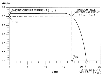
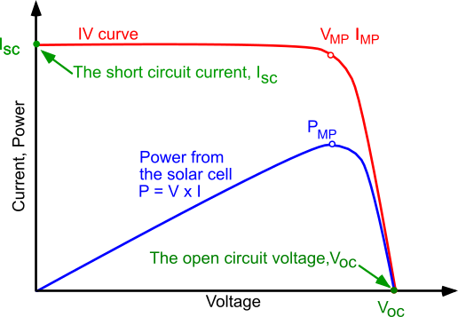
The key thing to remember is that the PWM controller is not bucking away any excess energy, the panel isn't making that energy. When a PWM charge controller is in bulk charge, it isn't doing anything, it is essentially just a wire between the panels and the battery. The battery is pulling the panel output voltage down to battery voltage, so the panel is operating near Vbattery and Isc. This is why PWM charge controllers generally don't need heat sinks. Adding some voltage drop to the wires means that the panel is now operating at Vbattery + Vdrop at Isc. The voltage drop is offset by the panel voltage increasing.

You are right that the wires can only dissipate so much heat, but that is why you need to consider the wire ampacity (see the table posted previously). In this case the 16AWG wires are operating at a max of 8A or less than 1/3 their rated ampacity of 25A. There is no reason to use larger wire in this application.
 

Rando

Explorer
Yes both sticking with old-school PWM and low voltage panels

**and** using inappropriately thin gauge cabling

is leaving significant power on the table that could be going into your bank.

....

I think you are missing the point. With the current panel and PWM controller the wire is not inappropriately thin and it not causing the loss of any power. Yes you could get more power form higher voltage panels, and MPPT and larger wire, but that wasn't the question.
 

DaveInDenver

Middle Income Semi-Redneck
The key thing to remember is that the PWM controller is not bucking away any excess energy, the panel isn't making that energy. When a PWM charge controller is in bulk charge, it isn't doing anything, it is essentially just a wire between the panels and the battery. The battery is pulling the panel output voltage down to battery voltage, so the panel is operating near Vbattery and Isc. This is why PWM charge controllers generally don't need heat sinks. Adding some voltage drop to the wires means that the panel is now operating at Vbattery + Vdrop at Isc. The voltage drop is offset by the panel voltage increasing.

You are right that the wires can only dissipate so much heat, but that is why you need to consider the wire ampacity (see the table posted previously). In this case the 16AWG wires are operating at a max of 8A or less than 1/3 their rated ampacity of 25A. There is no reason to use larger wire in this application.
Point taken. Voltage drop is power lost. At 100% PWM duty cycle during bulk that's power that could have gone into the battery instead of heating the wire.
 
Last edited:

rruff

Explorer
This is probably too late - but as your charge controller is of the PWM variety, there is no issue with voltage drop between the panels and the charge controller. The system is already dropping the 17-19V from the panels down to 13-14V charge voltage for the batteries, so as long as you are losing less than 2-3V in your wires, there is no power to be lost by using the 16AWG wires you already have.

There is no "dropping down" of the voltage from 18v of the panel to 13v of the battery. Rather the battery is controlling the panel voltage at 13v + the wire voltage drop. Hmm... so what you are saying is since the panel V-I curve is flat in that range, any power lost in the wiring is exactly compensated by the panel having higher output. That sounds right! Weird...

I-V_curve.gif
 

Rando

Explorer
Voltage drop is current lost. At 100% PWM duty cycle during bulk that's energy that could have gone into the battery instead of heating the wire.

Not in this situation. Solar panels are current sources - to the first order they output essentially a fixed current regardless of the voltage up until Vmp, then the current drops rapidly. So as long as you stay below Vmp then the current to the battery is unchanged at Isc (see the figure below). A voltage drop is power lost to heat, but this is power the panel was not producing previously.

IV_curve_solar_cell.png
 

Rando

Explorer
Exactly right. You will notice I said 'system' not 'controller' to not confuse folks even further.

There is no "dropping down" of the voltage from 18v of the panel to 13v of the battery. Rather the battery is controlling the panel voltage at 13v + the wire voltage drop. Hmm... so what you are saying is since the panel V-I curve is flat in that range, any power lost in the wiring is exactly compensated by the panel having higher output. That sounds right! Weird...

That's one of the nice things about MPPT... it lets the panel run at it's optimal power output. Plus you can use higher voltage panels to greatly reduce wiring losses.

I-V_curve.gif
 

OllieChristopher

Well-known member
Right on Rando, You are a pretty sharp dude. I'm all for learning another option for wire sizing and the advantage of using a PWM controller for your charging system. Interesting math showing that voltage drop is a concern when using MPPT technology. Math is not one of my strong suits!! LOL

What I am getting from this is if we are using a smaller array of solar panels, a PWM controller and smaller sized wires, it can make for a great budget system without too much efficiency loss.
 

rruff

Explorer
What I am getting from this is if we are using a smaller array of solar panels, a PWM controller and smaller sized wires, it can make for a great budget system without too much efficiency loss.

If you have a PWM controller and the voltage drop in your wires is <3V, you gain *nothing* by making the wires bigger. But I think you'll still be losing around 15-20% compared to MPPT. If you wire your panels for 24V (MPPT) you can still use small wires and have good efficiency. Doubling the voltage decreases the loss by 4x.
 

Forum statistics

Threads
188,342
Messages
2,905,815
Members
229,959
Latest member
bdpkauai
Top