Sprinter 4WD Conversion Idea, GMT-800 IFS.

Len.Barron

Observer
At this point I have no plans to change the sprinter's MC/booster. It works well, and I am trying to keep this projects scope under control!

I need to get some measurements of the GM calipers pad and piston area to compare to the sprinter.

I don't have my ball joints tools with me currently, so I need to make a trip to the auto parts store for a loaner.

I've never looked at a sprinter brake system so it was just a thought, I do know the gm calipers are pretty massive and the piston/cylinder volume is larger than most...just another thing to look at. If your UCAs are rusty at all and balljoints are questionable I'd probably just buy new, they are cheap on rockauto...save you a bunch of work.
 

luthj

Engineer In Residence
Getting some details into the model. Its not easy to get good measurements off the sprinter, especially the upper mount placement.

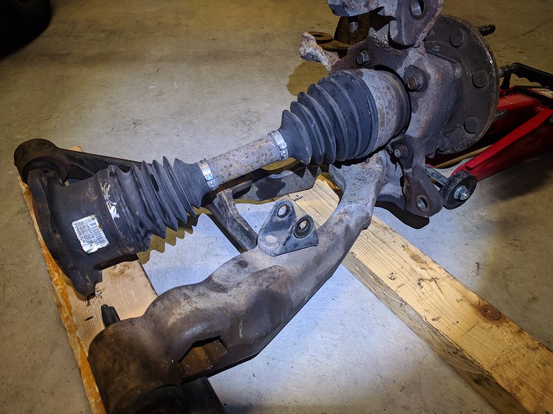
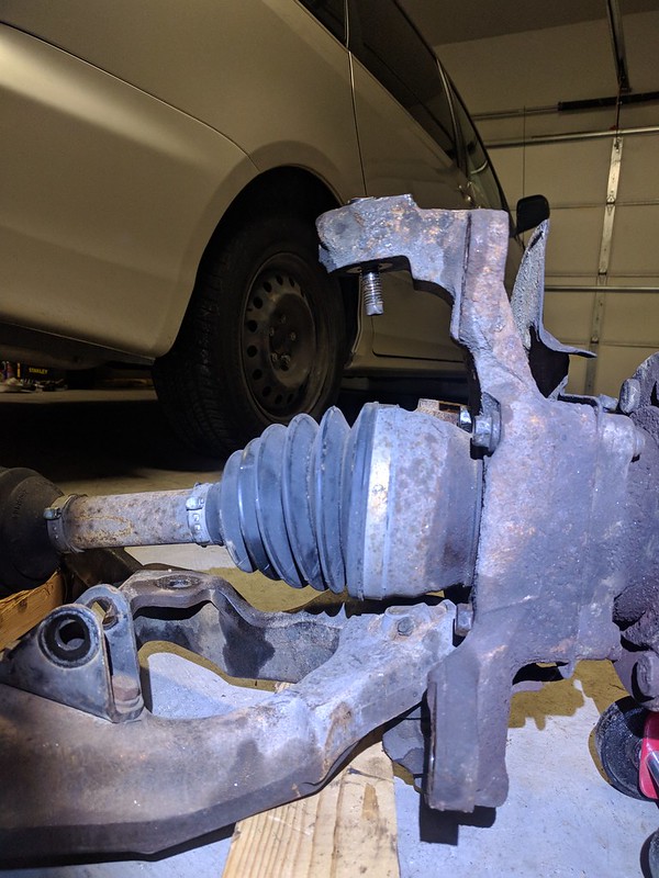
Ran into a bit of a roadblock. The Sprinters strut body is 15" long. The GM 2500 outer CV is nearly 5" in diameter. (much larger than the 1500 CV). In order to clear the CV and have enough up travel, I am looking at a ride height nearly 4" higher than current, 6" higher than stock. The euro strut is about an inch shorter, which helps. I am going to look at the later sprinter struts. Not likely they are shorter, but can't hurt to check.

1547837568391.png


luthj

Engineer In Residence
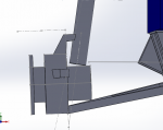
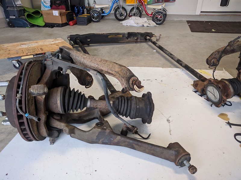
I did some rough measuring of the GM upper A-arm. It actually might be short enough to fit in the sprinter wheel well. I added a few sections to my subframe part. This shows some promise. I can use the GM upper A-arms with a riser section on the subframe. This will wrap around the sprinters "frame" rails. I still need to work out how to mount the GM shock. It will take some creative thinking to make clearance for the tirerods, and still have enough meat to support the upper arms. If this works out, it solves attaching a strut to the knuckle. It does mean I will need some kind of bracket for the shock upper mount. Hmmm,

1547840391049.png
 
Last edited:

luthj

Engineer In Residence
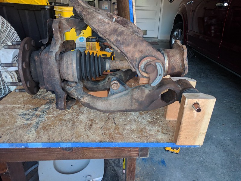
Okay, made a quick jig from some scrap wood. The upper A-arm mount just barely fits inside the sprinter wheel well. But only if I push the track width up to about 68-69", that will still require a small clearance window to be cut in the frame rail. Which is not ideal. The 3500 series trucks use a 125mm offset wheel. Which with wheel spacers may allow me to reclaim some of that track width. Assuming the wheels clear the suspension of course...

The CV axles should handle the extra width, but I need to confirm.


attachment.php
 

luthj

Engineer In Residence
Still chipping away. The GM bits are looking pretty good. Here we have normal ride height. The lower A-arm looks weird, as I am too lazy to accurately model the curve it has. Interestingly adding pieces to support the upper A-arm has solved two problems. It has provided a second support for the engine mounts, which were too far back to tie into the front/lower A-arm. It also required me to extend the subframe about 2 inches farther back. This allows room to move the rear cross-over to clear the Diffs rear mount.

1547923408405.png
You will notice that the engine mount is interfering with the steering input shaft. Not sure what I want to do here. I can cut the diff mounting tab off, and relocate with the aftermarket lift bracket. There may just enough room though.

1547923657879.png
 

luthj

Engineer In Residence
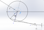
Another minor milestone. I did a steering analysis (2d). Despite Moving the steering rack forward to clear the diff, I can maintain 50% ackerman conservatively. Likely closer to 70%. Ideally I would want 90%, but GM positioned their steering arms using their offset center link. No way I can emulate that with a rack/pinion. Below is my sketch. At 30 degree steering angle (inside) I am about 1 degree off perfect ackerman (outside wheel is at 28.5 degrees). Due to the lack of accuracy, I could be off 3/8" on the steering shaft placement, so the range is 3.5-1 degree ackerman. Zero ackerman would be 7.25 degrees). I need to measure the lock-lock steering angle on the GM knuckles. The knuckles have an integral stop, so that takes some of the guesswork out of preserving the CV joints.
1547939101052.png
 
Last edited:

luthj

Engineer In Residence
Finally feel like I made some good progress. I realized I clocked the Diff mounts wrong. The pinion is 10 degrees off from the passenger side mount, and the flats on the case top. So the steering rack just squeaks by now.

1547952305290.png

Got the rear diff mount dialed in. I am starting with a pinion angle of 5 degrees, with room to go plus/minus 4 degrees either way.
1547952412606.png

Unfortunately my version of solidworks (2017) doesn't support automatic slot and tab creation! I may need to upgrade... By creating slots/tabs on adjacent bodies, I can essentially assemble/weld the entire subframe without a jig! Other good news, looks like the GM sway bar will bolt to the front of the subframe (similar to sprinters bar).


There is no substitute for hands on. Here is the beginnings of a jig to double check all my dimensions. Eventually I will have upper A-arm mounts and diff mounts.


I haven't decided what material thicknesses to use. For simplicity's sake and costs, I will try to stick with just 2 sizes. Though I may have some short lengths of tubing or bushing stock. Right now I am just using 3/16 sheet stock, and 0.25" bar/plate. If I haven't screwed anything up, I should be able to just change a variable for stock size. Last I checked the subframe was looking at around 60lbs. I am sure another 15lbs will be added before the end. The whole assembly with diff and suspension will weigh at least 450lbs (without tires).
 
Last edited:

mgmetalworks

Explorer
The slot/tab feature in SW '18-up is both awesome and super frustrating at the same time. I use it, but...sometimes I want to throw my laptop across the shop. :)
 

b dkw1

Observer
The slot/tab feature in SW '18-up is both awesome and super frustrating at the same time. I use it, but...sometimes I want to throw my laptop across the shop. :)

I feel that way about SW all the time.


Awesome project! Good choice on keeping the upper arm.
 

luthj

Engineer In Residence
I feel that way about SW all the time.


Awesome project! Good choice on keeping the upper arm.

Yeah, I feel like SW sketch system could learn a lot from Autocad...

The slot/tab feature in SW '18-up is both awesome and super frustrating at the same time. I use it, but...sometimes I want to throw my laptop across the shop. :)

Lol, Maybe thats why my last job had the computers bolted down?
 

luthj

Engineer In Residence
Currently I am working on the upper arm placement. Anyone with experience on taller CG vehicles have input on anti-dive percentages? It looks like GM has a bit of anti-dive on their suspension. For reference a 3 degree drop on the upper arm pivot gets me ~12% anti-dive with 0.25 caster gain per inch (bump). I am limited in what I can do to the lower arm due to the Torsion bars. Regardless too much caster gain in bump would be undesirable.

My rough math has the front at 65% of braking force, and the CG at around 52". In reality is probably a fair bit closer to the ground than that though.

I am also looking at roll center placement. Obviously heavy on-road cars are a bit different than track/dirt machines. With double A-arms, I am going to have much less camber change than the sprinter strut (which is a good thing, as it was a bit excessive). I think the sprinter was something like 0.5 deg per inch? Probably higher. Some rough sketching puts the roll center about 5" above ground. Though I think 7-15" is closer to ideal.
 
Last edited:

b dkw1

Observer
How much travel are you trying to squeeze out of it? More than stock you will need to take some angle out of the upper mount. Try and keep about the same amount of castor gain regardless of what travel you end up with.

Be glad your not building a Tacoma LOL.......
 

luthj

Engineer In Residence
If I could get 9" I would be happy. 3.5 up and 4.5 down would be acceptable (better than the 7" I got now!)
 

locrwln

Expedition Leader
Another minor milestone. I did a steering analysis (2d). Despite Moving the steering rack forward to clear the diff, I can maintain 50% ackerman conservatively. Likely closer to 70%. Ideally I would want 90%, but GM positioned their steering arms using their offset center link. No way I can emulate that with a rack/pinion. Below is my sketch. At 30 degree steering angle (inside) I am about 1 degree off perfect ackerman (outside wheel is at 28.5 degrees). Due to the lack of accuracy, I could be off 3/8" on the steering shaft placement, so the range is 3.5-1 degree ackerman. Zero ackerman would be 7.25 degrees). I need to measure the lock-lock steering angle on the GM knuckles. The knuckles have an integral stop, so that takes some of the guesswork out of preserving the CV joints.
View attachment 494409


Not sure the exact measurements, but I do know that the stock GM 2500 steering system is set for roughly 6" of travel side to side. The 1500 stuff has a pretty tight turning radius, but the 2500/3500 stuff has a much large turning radius. I think they did it to preserve the CV's under the load/power that the front end could see in an HD truck.

Jack
 

Forum statistics

Threads
188,168
Messages
2,903,014
Members
229,658
Latest member
rjparnow415
Top