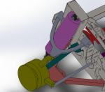
Sprinter 4WD Conversion Idea, GMT-800 IFS.

luthj

Engineer In Residence
Okay, pulled some data while spinning one front wheel. I have the Due CAN-CAN bridge connected to the CANbus to capture frames.

Confirmed 0x200 is the front wheels. So 0x208 must be rear. Byte 5 and 6 are right, byte 7 and 8 are left. Byte 6/8 are low bytes, 5/7 are high bytes. It looks like bytes 3/4 are the average bytes (likely for speedometer?). I am assuming, as I can't spin both wheels right now. If I have the time I will rig the due to spoof some speed packets.

Looks like I had the speed change code backwards, as the Due is little endian. So I swapped the low/high bytes on my wheel speed integers.

With nothing but a 60 ohm termination resistor on the Dues CAN2 port, it is giving me transmission errors when it tries to forward the packs from CAN1. I am a bit stumped, as my code looks good. I guess I need to write some more debug output into it.
 

luthj

Engineer In Residence
I resolved some issues with the CAN-CAN program. (wayward bracket!!!) and cleaned up the debug printouts, and sped it up by moving some stuff outside a for loop.


I am still getting an error, but the LED shows its transmitting. I suspect it must not be seeing the synchronization signal, so the controller must know there is nothing else on the dangling CAN2 segment. I located the splice I want under the drivers seat, so I can be certain only the TCM is on one side, and the rest of the system on the other.

There are two schemes for terminating CANbus, one is two have 2 resistors, once at each end. The more fault tolerant version uses a resister at each node. I need to play with it a bit to see which the sprinter uses.

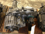
I think I have tracked down a Tcase, input shaft, adapter case, etc. I need to drive an hour to grab it next week. Sooooon.

C++:
void loop()
{
  // Declarations
  byte cPort, cTxPort;
  long lMsgID;
  bool bExtendedFormat;
  byte cData[8];
  byte bData[4];
  byte cDataLen;
  int lowrange = false;
  unsigned short wSpeedL;
  unsigned short wSpeedR;
  unsigned short wSpeedA;
  unsigned long previousMillis = 0;
  unsigned long Pinterval = 1000;
  //Serial printing interval
  bool SERIAL_OUTPUT = true;

  // Start timer for LED indicators
  TimerStart(&pTimerLEDs, TIMER_RATE_LED_BLINK);

  while (1) // Endless loop
  {
    // Control LED status according to CAN traffic
    LEDControl();

    //Read low range switch and assign to lowrange varaible
    //lowrange = digitalRead(LRSW);

    //Serial Print Interval

    if ( SERIAL_DEBUG = true)
    {
      unsigned long currentMillis = millis();
      if ((currentMillis - previousMillis) >= Pinterval)
      {
        // save the last time Serial Printing Occured
        previousMillis = currentMillis;
        // Set Print to serial
        SERIAL_OUTPUT = true;

      }// end if
      else (SERIAL_OUTPUT = false);

    }//end if
    // Check for received CAN messages
    for (cPort = 0; cPort <= 1; cPort++)
    {
      // removed lowrange == true
      if (canRx(cPort, &lMsgID, &bExtendedFormat, &cData[0], &cDataLen) == CAN_OK  )
      {
        // Scan through the mapping list, If frame matches ID
        for (int nIndex = 0; nIndex < nMappingEntries; nIndex++)
        {
          if (lMsgID == CAN_DataMapping[nIndex].lReceivingMsgID)
            // Removed matching for source CAN port
            // && cPort == CAN_DataMapping[nIndex].cReceivingPort
          {

            if (SERIAL_OUTPUT)
            {

              Serial.print("cPort");
              Serial.print("\t");
              Serial.print("lMsgID");
              Serial.print("\t");
              Serial.println("cData [4]..[7]");
              Serial.print(cPort);
              Serial.print("\t");
              Serial.print(lMsgID, HEX);
              Serial.print("\t");

              for (int mIndex = 4; mIndex <= 7; mIndex++)
              {
                Serial.print(cData[mIndex], HEX);
                Serial.print(":");
              }//end for loop
              Serial.println();
            }

            //If recieved port is CAN0, transmit on CAN1, otherwise transmit on CAN0.
            cTxPort = 0;
            if (cPort == 0) cTxPort = 1;

            //Initialize wheel speed int to zero
            wSpeedL = 0;
            wSpeedR = 0;
            wSpeedA = 0;

            //copy speed data bytes to working array from CAN data array
            bData[0] = cData[5];
            bData[1] = cData[4];
            bData[2] = cData[7];
            bData[3] = cData[6];

            //Set wSpeed to array data
            wSpeedR = (wSpeedL  << 8) + bData[0];
            wSpeedR = (wSpeedL  << 8) + bData[1];
            wSpeedL = (wSpeedR  << 8) + bData[2];
            wSpeedL = (wSpeedR  << 8) + bData[3];

            //print data for debug
            if (SERIAL_OUTPUT)
            {

              Serial.print("wSpeedL raw");
              Serial.print("\t");
              Serial.println("wSpeedR raw");
              Serial.print(wSpeedL);
              Serial.print("\t");
              Serial.println(wSpeedR);
            }

            //For Front wheels, frame 0x200, adjust front wheel average speed.
            if (lMsgID == 0x200)
            {
              // copy speed data to wSpeedA
              wSpeedA = (wSpeedA  << 8) + cData[3];
              wSpeedA = (wSpeedA  << 8) + cData[2];

              //debug printing
              //if (SERIAL_OUTPUT)
              //  {
              //  Serial.println("Front average speed CAN Raw, cData[2]..[3] wSpeedA  ");
              //  Serial.print(cData[2], HEX);
              //  Serial.print(":");
              //  Serial.print(cData[3], HEX);
              //   Serial.println(wSpeedA);
              //  }
              //divide average speed by 2.73 using binary scale factor,  ((1/2.73)*4096) = 1500
              wSpeedA = ((wSpeedA * 1500) >> 12);

              if (SERIAL_OUTPUT)
              {
                Serial.print("wSpeedA divided = ");
                Serial.println(wSpeedA);
              }//end If

              //Copy revised speed to data array
              // memcpy ((byte*)cData[2], (byte*) & (wSpeedA), sizeof(wSpeedA));
              cData[2] = highByte(wSpeedA);
              cData[3] = lowByte(wSpeedA);
              if (SERIAL_OUTPUT)
              {
                Serial.println("Front average speed Converted Raw, cData[2]..[3]");
                Serial.print(cData[2], HEX);
                Serial.print("\t");
                Serial.println(cData[3], HEX);
              }
            } //end if

            //Divide Wheel speeds by 2.73 using binary scale factor,  ((1/2.73)*4096) = 1500
            wSpeedL = ((wSpeedL * 1500) >> 12);
            wSpeedR = ((wSpeedR * 1500) >> 12);

            //print data for debug
           if (SERIAL_OUTPUT)
              {
            Serial.println();
            Serial.print("wSpeedL divided, wSpeedR divided ");
            Serial.print(wSpeedL);
            Serial.print("\t");
            Serial.println(wSpeedR);
              }//end If

            //Copy wSpeedL and wSpeedR to working array, Note offset for start byte.  Assumes both CAN frame and chip are little endian
            // memcpy( (byte*)bData[0], (byte*) & (wSpeedL), sizeof(wSpeedL));
            //memcpy( (byte*)bData[2], (byte*) & (wSpeedR), sizeof(wSpeedR));
            bData[0] = highByte(wSpeedL);
            bData[1] = lowByte(wSpeedL);
            bData[2] = highByte(wSpeedL);
            bData[3] = lowByte(wSpeedL);

            //Print working array contents
            if (SERIAL_OUTPUT)
            {
              Serial.println("bData[0]..[3]");
              for (int mIndex = 0; mIndex <= 3; mIndex++)
              {

                Serial.print(bData[mIndex], HEX);
                Serial.print(":");
              }//end for loop
              Serial.println();
            }//end If

            //Copy bData to data array
            cData[5] = bData[0];
            cData[4] = bData[1];
            cData[7] = bData[2];
            cData[6] = bData[3];

            // Transmit Frame, print error message if CAN_ERROR is returned
            if (canTx(cTxPort, lMsgID, bExtendedFormat, &cData[0], cDataLen) == CAN_ERROR)
            {

              Serial.println("Transmision Error2.");
              Serial.print(cTxPort);
              Serial.print("\t");
              Serial.print(lMsgID, HEX);
              Serial.print("\t");
              Serial.print(bExtendedFormat);
              Serial.print("\t");

              for (int mIndex = 0; mIndex < cDataLen; mIndex++)
              {
                Serial.print(cData[mIndex], HEX);
                Serial.print(":");
              }
              Serial.print("\t");
              Serial.println(cDataLen);


            }
          } //end if


          //Transmit Frames If low range is not active, or for non-matching frames
          else
          {
            //If recieved port is CAN0, transmit on CAN1, otherwise transmit on CAN0.
            cTxPort = 0;
            if (cPort == 0) cTxPort = 1;

            if (canTx(cTxPort, lMsgID, bExtendedFormat, &cData[0], cDataLen) == CAN_ERROR)
            {
              if (lMsgID == 0x200 || lMsgID == 0x208)
              {
                //Serial.println("Transmision Error1.");
                Serial.print(cTxPort);
                Serial.print("\t");
                Serial.print(lMsgID, HEX);
                Serial.print("\t");
                Serial.print(bExtendedFormat);
                Serial.print("\t");
                for (int mIndex = 0; mIndex < cDataLen; mIndex++)
                {
                  Serial.print(cData[mIndex], HEX);
                  Serial.print(":");
                }
                Serial.print("\t");
                Serial.println(cDataLen);
              }
            }
          }// end if else

        }// end for

      }// end if

    }// end for
  } //end while
} //end loop
 

luthj

Engineer In Residence
I have learned what is needed to attach a 242 (or 241, possibly 23X series too) to a NAG1/WA580 transmission.

First you need a transmission housing (or complete trans) with the flange on the output side. Many 4wd jeeps from 06-10 have such a trans. The wrangers from late 2012-present use the NAG1 variant needed.

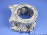
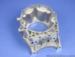
Next an adapter housing is needed. MOPAR 52108644AA. This was used only on a rare number of Diesel Grand cherokees in the USA, but is common in europe. This is also used on 2012+ wranglers with 5 speed auto and NV241 tcase.
520379
520380


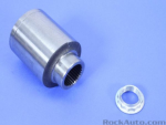
The intermediate shaft is 5179989AA. This will likely be already on the transmission, as it is used with most Tcases attached to the NAG1. The exception is the rocktrac. Note that the Tcase side has external splines.
520386

520390

Finally, the tcase must have a matching input gear. MOPAR 68087960AA. The 242 was only offered with the NAG1 in the diesel grand cherokee, and they likely used a different intermediate shaft and standard input gear. These can be obtained from a 2012+ 5 speed wrangler with 241 Tcase.

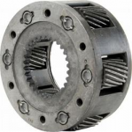
I am going with a 242D from a 98-99 dodge durango. This tcase has the second strongest chain option ever offered, only exceeded by the HMMWV version. It has 32 spline output shafts. It can be further strengthened by installing a 6 planetary gearset from a truck sourced 231. Any tcase made after 95+will for sure have planetary gears compatible with the new style input gear. There are two widths of input bearing, so measure and check first.

520389

520388

I plan on picking up a tcase on Saturday. I am still inquiring about a wrangler I can get the input gear from. These parts are all available new, but its 120$ for the gear, 240 for the adapter housing, and 50$ for the intermediate shaft.
 
Last edited:

Len.Barron

Observer
Did you consider just using the NP241J from a late model wrangler? They are set up with fixed outputs both front and rear rather than slip yokes...not sure if that would be a pro or con for your build.
 

luthj

Engineer In Residence
Did you consider just using the NP241J from a late model wrangler? They are set up with fixed outputs both front and rear rather than slip yokes...not sure if that would be a pro or con for your build.

I did, they are a good option. However, a significant part of my 4WD needs are mixed highway driving in winter weather. Also driving at speed on packed dirt roads. At speed the ESP is quite helpful, and locked center diff would interfere some. Plus having to constantly shift from 2WD to 4WD part-time in winter would suck. The 242 has the full-time option, which really expands the usage in my view, and helps keep drive-line loading low when on high traction surfaces. That being said, the front axle actuator on the GM diff does allow for on the fly 4wd to 2WD changes without shifting the Tcase.

Finally, an update I can understand.

?

Here comes something a bit simpler too.


I spliced the CAN bridge in and took the van for a drive. Works without issue. The only minor hiccup is that the TCM goes to sleep with key off, but other modules continue transmitting. I will just wire the bridge so that its powered from the same circuit as the TCM. This model supports 7-36V input, but I will probably put some additional protection on the power supply just in case.

It easily connects with screw clamp plugs, which can easily be removed to service the unit, or reflash firmware if desired. Now I just need to make a small enclosure to mount and protect the unit.


[url=https://flic.kr/p/2g9ZX5Q]

Basically, now I have a low range fix that can be retrofitted to any T1N sprinter with 6 wires. Its standalone, and transparent to the vehicle.
 

Len.Barron

Observer
I did, they are a good option. However, a significant part of my 4WD needs are mixed highway driving in winter weather. Also driving at speed on packed dirt roads. At speed the ESP is quite helpful, and locked center diff would interfere some. Plus having to constantly shift from 2WD to 4WD part-time in winter would suck. The 242 has the full-time option, which really expands the usage in my view, and helps keep drive-line loading low when on high traction surfaces. That being said, the front axle actuator on the GM diff does allow for on the fly 4wd to 2WD changes without shifting the Tcase.
Yep, that makes sense, living in San Diego I never really consider routine snow driving, it's an "event" when I do it and I did the push button NP263xhd so it's really no big deal for me..
 

Paddy

Adventurer
shifting between 2hi and 4hi isn’t inconvenient at all to me. Just grab a lever and pull, at speed up to 65.
Locking in hubs however, is slightly annoying. But I’d still rather have them than not
 

luthj

Engineer In Residence
More progress on the speed sensor modifier circuit (FWB).

I assembled the FWB with trigger input circuit. For testing the arduino is driving the PWM pin at 50% (~950hz).


Here is the input waveform.


With some changes to the program (thanks M!), i turned on the time adjustment multiplier (1.25). Below is the output waveform. You will notice a slightly increased wavelength. 25% to be precise! Looks uniform cycle to cycle. Looks like the uno is more than fast enough for 2 channels at 90mph.


Once I get the output bit designed, this should be a fairly versatile solution. It could be used anywhere that tone ring differences exist, axle swaps, or even adjusting for gear ratio changes to speedometers, etc.
 

luthj

Engineer In Residence
shifting between 2hi and 4hi isn’t inconvenient at all to me. Just grab a lever and pull, at speed up to 65.
Locking in hubs however, is slightly annoying. But I’d still rather have them than not

Yeah, its just preference. My shifter will be LOW down, as the sprinter has a very high seating position. I can't see over the dash and reach the likely shifter location. I was considering a dash mounted cable shifter, but I haven't wrapped my head around how to mount it. Not much structure for a ways behind the plastic bits.
 

luthj

Engineer In Residence
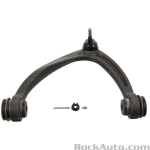
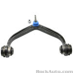
I ordered a GMT900 1500 series UCA. These vehicles have coils from the factory, so I thought they might fit.

521320

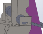
They do clear the coil spring at droop/bump. However they are about 0.87" farther from bushing to BJ.

521321

This pushes the bushings into the frame rail a fair bit. Enough that I am concerned they will hit the attachment bolts.

521322

I think I have a solution though. There are aftermarket versions of this UCA with a eccentric mounted BJ. Some eyeballing of the photos, puts the offset at around 0.75". That would wipe out most of the frame interference, and actually improve coil clearance.

521323


So next steps are to confirm what the 2500 upper BJ taper is. If they don't match, I need to see what my options are for retrofitting a joint with correct taper (not likely with the eccentric/adjustable version). Obviously I need to reworking my rear mount some, and the front needs moved back a few inches.
 

luthj

Engineer In Residence
Well the BJ is too small. The taper is the same, but the overall diameter is about .08 too small. Back to the drawing board. The 2013+ 2500 UCA looks similar.
521324

I see some taper sleeves for GM lift kits. I wonder if these would work?

http://www.socalsupertrucks.com/1999-2006-gm-1500-upper-ball-Joint-taper-sleeves.aspx#.XP7ZuhZKjRY

521325

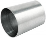
CNC machined sleeve coverts big taper spindle to use the smaller tapered ball joint and are sold as a pair.

Rough measurements put the 2500 BJ at 2.0in/ft of taper. It varies from .616 to .777". The tapered section is about 1" long, and the threads 1.1".

These sleeves are 2.0 taper, but seem a bit on the large side. hmmm, maybe I could grind them down?

https://www.summitracing.com/parts/aaf-all56225

521326


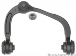
Another option might be F150 UCAs. They might use a larger BJ taper.

521351
 
Last edited:

Len.Barron

Observer
there's a lot of offset ball joints out there, just look on summitracing.com see if you can find some for a heavier truck, here's some from a Ram 3500 which would have a beefy BJ https://www.summitracing.com/parts/mog-k7448/applications
At worst you'd have to open up the hole on the control arm but that would be a pretty simple fix..
looks like SPC makes a bunch..
 

luthj

Engineer In Residence
Yeah, some options. The 2014+ UCAs have a non replaceable BJ. Not much meat there for machining.

The 2013+ 2500 UCA is a cast/forged design, and is much lower profile. I think I will order one, as it am hopeful it has the larger BJ taper.

Another options I was considering is getting some 1/2" x .035 aluminum tubing. I could cut 2-3 partial conical sections from it, and use those as spacers around the smaller BJ shaft. Should get a nice tight fit, and proper engagement depth.

I found another 242D nearby. Unknown miles, but only 150$. Should pick it up tomorrow.
 

Len.Barron

Observer
Yeah, some options. The 2014+ UCAs have a non replaceable BJ. Not much meat there for machining.

The 2013+ 2500 UCA is a cast/forged design, and is much lower profile. I think I will order one, as it am hopeful it has the larger BJ taper.

Another options I was considering is getting some 1/2" x .035 aluminum tubing. I could cut 2-3 partial conical sections from it, and use those as spacers around the smaller BJ shaft. Should get a nice tight fit, and proper engagement depth.

I found another 242D nearby. Unknown miles, but only 150$. Should pick it up tomorrow.
There are a bunch of 4x4 fab shops that sell taper adapters, I'm sure you can find one that has what you need..
 

Forum statistics

Threads
188,163
Messages
2,902,927
Members
229,582
Latest member
JSKepler

Members online

Top