The Rolling Restoration & Customization Of My 88' Range Rover Classic

rrclassicbt550

Farmer Jon
Status Update on the Rover

The status of my Rover is drivable but not yet street legal because I still need to wire run new “power” and “ignition on” wires for the radio harness, wire in a new “hazard lights” switch and then wire the turn signals so that they work, and the same goes for wiring in the windscreen wipers. Other than those things, the Rover is ready to get back on the road! Once I get it street legal again and am finally able to enjoy actually driving it again I am going to be utilizing the “weekend jobs” approach to put on the rest of the add ons/mods.


There were more small jobs than I originally anticipated. Gladly, I have completed a great deal of them now and after each one was completed I celebrated small victory to help push on through the rest. It is so nice to see this Rover really coming back together!

So here goes the pictures and write ups for many of those little jobs (in no particular order):
 

rrclassicbt550

Farmer Jon
Inertia Switch

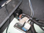
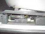
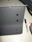
I relocated the inertia switch from under the drivers side seat to. My reasoning is that it should still perform in a similar manner when located in its mirrored location under the passenger side seat as it would have when it was located under the drivers side seat.

It was pretty simple to install. Just re-route the wires, drill two holes, and secure it with two screws.

IMG_0153.JPG
 

rrclassicbt550

Farmer Jon
How to get just a little bit more tilt from steering column....

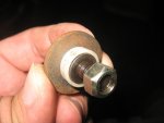
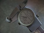
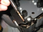
The steering wheel position after everything was bolted in place still felt about a half inch too high so I pulled steering column back out and removed the two plastic rings that were on the bolts which restricted the range of motion for the tilt mechanism. Removing these to plastic rings gain .065” which may not sound like much but that made the wheel come down another 3/8” when in the tilted down position. I know 3/8" is not quite a ½”, but its close enough and removing that .065” leaves just enough clearance for the universal joint in the steering column to rotate freely and safely without any fear of it binding or locking up. I would rather be safe and deal with 3/8” more travel, then try to get closer to a ½”and potentially unsafe, because in all honesty another 1/8” in travel will be almost unnoticeable and not worth the risk.

The steering wheel placement feels perfect now. I can still see all of the gauges at an easy glance, and since the 1995 RRC steering column is a little bit longer then the 1988 Steering column, I can finally move the seat further back so that I can enjoy the wonderful amount of leg room an RRC offers, while feeling like I am actually able to control the steering should I have to perform an evasive maneuver to avoid something. With the old steering wheel and column set up, I always felt like I was riding above the natural center of gravity while driving a bus at arms length and never fully feeling in control when the situation got a little iffy. Now the driving position is much MUCH nicer in my opinion.

Here are some pictures of the plastic rings I took out...

IMG_7291.jpgIMG_7293.JPGIMG_7286.jpg
 

rrclassicbt550

Farmer Jon
Fixing the issue with the Passenger side seat lift mechanism...

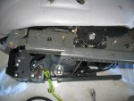
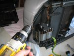
I found an interesting fault with my passenger side seat while I had it out to put in the inertia switch. The front-left side of the seat never fully lifted when using the switch. I seemed like it had been jammed or something. Upon closer investigation though, what had actually happened was that the drive cable had slipped out of the retainer just enough to not make contact with the motor anymore and ended up letting the other side lift a little higher. Then the drive cable somehow slipped back in to place and could not then lift the left side as high as it should go. The problem was that because one side was higher than the other, the front-left side could never achieve full height because the front-right side always hit its highest limit first and then stopped.

It was a really easy fix. All I did was pull out the front–left side drive cable at the motor. Then put the end of it in my drill and ran the left side up to match the right side. Once they were at an even height I simply put the drive cable back into its retainer and tightened it. Now it works perfectly! I love an easy fix! Haha

IMG_0154.JPGIMG_0157.JPGIMG_0155.JPG
 

rrclassicbt550

Farmer Jon
Modifying the trim for the drivers side seat...

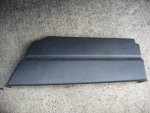
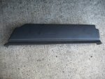
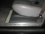
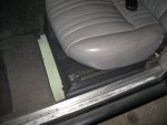
For the Drivers side seat trim I had to do a fair amount bit of trimming to make it look presentable but I think I achieved a nearly factory look. I did notice that because the seat mounts had to be cut down to lower the seat, it did have an effect on the area where the carpets and the trim meet.
There is a two-inch gap between the carpet and the trim panel at the moment and a small gap between the sill plate and the trim panel. So I will have to find some similar carpet a little later on or I am also thinking I might be able get the carpets out of another RRC (which is being parted out) to cut up and put in there so the fit and finish will be similar. Guess I will see how it goes, but it is good enough for the moment.

IMG_7193.JPGIMG_7189.jpgIMG_7196.JPGIMG_0223.JPGIMG_0221.JPG
 

rrclassicbt550

Farmer Jon
The two holes where the heater core pipes pass through the firewall...

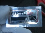
Thinking about the two holes where the heater core goes through the firewall has been bugging me to be for a while now. Since the new heater core I installed is both aftermarket and plastic, I have been worried that given enough time or a good distance over a roughly corrugated road, there might be contact made between the metal firewall and the plastic heater core pipes. You might imagine that this would not be a fun scenario to have to sort out while in the middle of nowhere (especially if it were in the winter months). So I decided to use Sugru (yet again) to create a grommet/water proof seal that will be heat resistant and still remain flexible. I know its not the perfect solution, but it will work very well and will put my mind at ease over a potential leak arising someday.

IMG_7244.jpgIMG_7255.jpgIMG_7384.jpg
 

rrclassicbt550

Farmer Jon
Finished the cargo area for now...

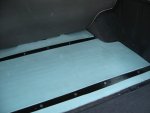
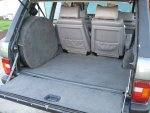
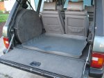
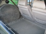
The back seats have been installed for quite a while now but I was slow to get around to cleaning and condition the panels for the seat backs, as well as gluing the rear carpet in and installing the mounts to hold the spare tire. However, I have now cleaned everything and installed it all so that I could finish out the rear cargo area.

As you can see by the pictures and also by using the original cargo liner as a visual size reference, the amount of space lost is minimal. I can still load of up the back full of gear and not worry about running out of space and since I can power the seats forward and detach/remove the seat backs, I will still maintain functional and useable storage space.
I plan on putting in a drawer system with a fold out sleeping platform in the not to distant future, that is why I modified the rear seatbacks so they could be detached.
IMG_0054.JPGIMG_0055.jpgIMG_0057.JPGIMG_0059.JPGIMG_0109.JPGIMG_0110.JPGIMG_0111.JPG

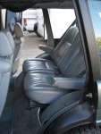
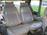
And here is another look at the back seats in place. I still need to fasten the carpet down around the seat frame, find some carpet to go under the seats, and run the auxiliary fuse box to power the seat rear seat switch panels and power outlets. If you look in the last picture you can get a preview of what the seat switch panels look like and where they will be placed. I will post the making of those panels/boxes another day...

IMG_0115.jpgIMG_0147.JPG
 

rrclassicbt550

Farmer Jon
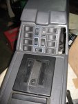
Front seat switch panel mounted in the center console...

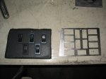
As many of you already know, I was extremely frustrated with the original Land Rover/Mercedes power seat switches. Because of this frustration I decided to make my own seat switches. I have already done the write up on how to make the seat switches but I have not shown how I installed them. Well, here is how I did it…

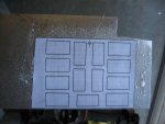
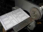
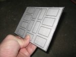
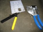
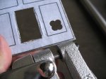
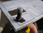
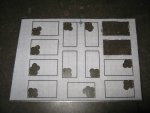
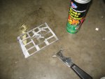
I laid out a new panel using my computer, printed the drawing out to the right scale, cut it out of the paper, and then glued the drawing to some 16-guage sheet metal. Doing it this way means that that I don’t have to spend a ton of time laying out and measuring. Not to mention if I make a mistake that means I have to start over, I can just print of another drawing and glue it to a new piece of metal in only a few minutes rather then spending a ton of time laying out cut lines and triple checking measurements. To get the paper off of the metal after it is all done, I use either brake clean or glass cleaner.

Since I do not have any spare vinyl I used the old vinyl off of the original power switch panel. Its not perfect but I am planning on doing more modifications to the center console in the future and I don't see the point in making it perfect if I am going to have to reupholster it shortly thereafter. Also because its a hard to see the vinyl with that many switches in just that one little area...haha ;)

IMG_0050.JPGIMG_0069.JPGIMG_0071.JPGIMG_0074.JPGIMG_0079.JPGIMG_0080.JPGIMG_0081.JPGIMG_0083.JPGIMG_0086.JPGIMG_0088.JPG
 

rrclassicbt550

Farmer Jon
Seat switch panel continued...

IMG_0089.JPGIMG_0090.JPGIMG_0091.JPGIMG_0093.JPGIMG_0098.JPGIMG_0100.jpg

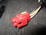
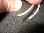
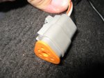
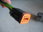
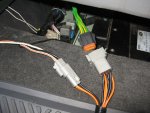
Here is how to install the new Deutsch connector in place or the original connectors. I covered the actual crimping process in the write up for making of the seat switches. This is just a quick reminder to help as a visual aid when installing the seat switches into the actual car.

IMG_0148.JPGIMG_0149.JPGIMG_0150.JPGIMG_0152.JPG
 

rrclassicbt550

Farmer Jon
Cleaning up the shifter...not strictly necessary...but every little bit helps...

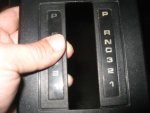
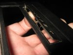
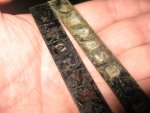
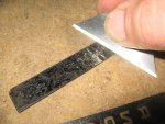
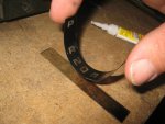
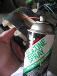
I know its not strictly necessary, but I decided to clean up and attempt a little preventative maintenance on the shifter piece. I popped out the lettered panels and took them apart to scrape out the terrible looking glue that had long since passed its ability to let light shine through. Then once they were clean, I super glued them back together and glued them back in place. I then thoroughly clean the piece that moves with the shifter and always seems to have an unfortunate propensity for tearing through when I shift down into the low gears. Because this is my third one, I want to give it the best chance I can so I also used some silicone lubricant to help it slide back and forth a little easier, as well as I lubed the actual shifter and its linkage so it would move more freely. It seems like nothing can ruin the look of a nice interior faster than when the area around the shifter is all torn up. Lastly, I also was very careful to line up the center panel in the the console to help reduce the possibility of any mishaps in the future.

You will be able to see the center console in its entirety in another post...but for now here are the pictures...

IMG_7298.JPGIMG_7299.JPGIMG_7303.jpgIMG_7306.JPGIMG_7309.JPGIMG_7315.JPGIMG_7316.JPGIMG_7317.JPGIMG_7322.JPGIMG_7333.jpg
 
Last edited:
rrclassicbt550

Farmer Jon
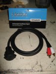
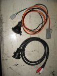
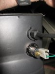
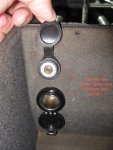
Relocating the 12v power outlet and adding in a stereo/auxiliary jack for the radio..

I am sure that many of you have had to deal with this problem before. Your ipod or mp3 players battery is nearly dead so you plug it in to the power outlet either by the radio or into the power outlet on the back of the center console. The problem is that when you stop at your destination you then have to decide where to discreetly place the rather expensive musical device while it charges so that it is not left in plain sight. However, when you do place said device in a discreet location there is still a cord that leads straight to the discreet hiding place. I know I can tuck the cord away under the panel, but I use the same usb cord inside the house so I take it with me and it would be annoying to have to tuck it under the panel every time I left my car for the night.

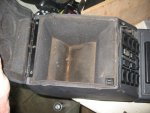
So, while I had the console out of the car, I took the opportunity to relocate the power outlet into the center consoles cubby box and also run an auxiliary jack into that same area as well.


IMG_0101.jpgIMG_0117.jpgIMG_0118.jpgIMG_0119.JPGIMG_0121.jpgIMG_0123.jpgIMG_0125.jpgIMG_0124.jpgIMG_3021.JPGIMG_0145.jpg
 

rrclassicbt550

Farmer Jon
Dual battery display mounting...

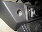
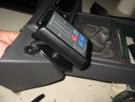
Having now relocated the power outlet....I had an unsightly hole in the panel next to the radio, but not to worry...I had plans. ;)

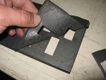
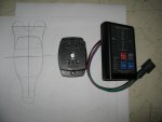
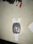
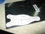
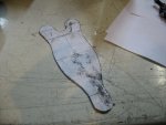
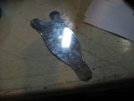
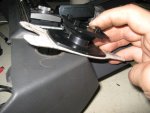
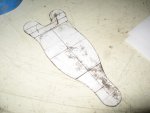
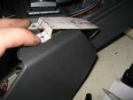
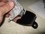
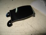
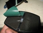
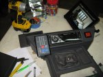
I took advantage of where the 12v outlet originally was to neatly run the wires to my dual battery systems display. The only issue was that I had to fabricate a bracket/mount to be able to make fit exactly where and how I want it to fit. I had some polished stainless steel laying around and decided to use that. I drew out what I wanted the mount to look like, then glued it to the plastic the was on the stainless steel to protect it. After I cut it all out and filed down the edges, I then removed the plastic which took the grubby looking paper template with it and revealed a nicely finished part. :)

Take a look...

IMG_0170.JPGIMG_0171.jpgIMG_0176.JPGIMG_0178.JPGIMG_0183.JPGIMG_0186.JPGIMG_0189.JPGIMG_0193.JPGIMG_0196.JPGIMG_0197.JPG
 

rrclassicbt550

Farmer Jon
Alright, I think that is enough posts for now. I will add more later on, but its late and I need to get some sleep. I hope you all enjoy them.

If you have any questions, please feel free to ask. :)

Have a goodnight everyone!

Jon
 

Forum statistics

Threads
186,657
Messages
2,888,536
Members
226,767
Latest member
Alexk
Top