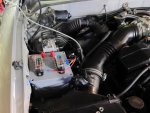
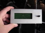
A year or so ago when I had my last (99) Tacoma, I was looking for a dual battery controller and was unimpressed with the commercial units, particularly for the price ($150 - $250!). So I decided to make my own. The first prototype worked well in my 99 Tacoma, up until it was bought back for rust issues. I have finally gotten around to putting together Mark II for my new ’04 Tacoma.
In short, it is a relay based (soon to be transistor based) micro processor controlled battery isolator and auxiliary load controller. It has a couple of features that make it a little more deluxe than what is commercially available:
• 4 line x 20 character LCD display in the cab to let you know the state of charge of the battery and what the controller is doing, and to adjust the operating parameters
• True battery capacity monitoring (in Ah remaining / % of charge / time to empty) based on the specific chemistry of the main and aux batteries and using charge and load current accounting (the same way that laptops keep track of their batteries). This is MUCH more accurate than measuring the voltage of a battery under load or under charge. The best part about this is that there is no more guessing about how long my fridge will run, the time-to-empty display lets me know that I can run my fridge for another 52 hours before I need to charge!
• Two individually controllable auxiliary fuse blocks for accessories – it measures the load current so it can estimate the run time available from the aux battery and can switch of each bank of accessories at predetermined state of charges (say 50% and 30%). Or you can configure it so that one is always on and the other is only on when the engine is running etc.
• A system to ensure that the starting battery gets fully charged before the aux battery is charged, as well as a time-to-full display so that I know how long I have to drive in order to fully recharge both batteries.
• Records statistics on the actual battery performance as opposed to rated battery performance so that I can watch my expensive Die Hard Platinum deteriorate over time. So far it has been performing better than rated.
• Fully re-programmable (it has a USB port) so that I can add more useless software gimmicks as I have more time.
• Safety monitoring so that it will isolate the batteries and/or disconnect the loads if the currents flowing to either are too high.
Enough with the sales brochure, and on to how it works. The brain is an Atmel ATmega328 microcontroller, in the form of an Arduino Duemilanove development board. This senses two current channels (the charge going into my aux battery and the current going out to the accessory fuse blocks) as well as the voltages of both the main and aux batteries. In general the state of charge of the aux battery is calculated by integrating the current going into the aux battery minus the current being used by the accessories. This works very well, but it subject to creep over long periods (weeks) due to the integration of small systematic errors. In order to compensate for this I periodically recalibrate this value when the battery has been at rest for 12 hours or more at room temperature (ie no charging and no loads) based on the open circuit voltage to state of charge function provided by Odyssey. I do the same thing for the starting battery based on the standard flooded lead acid charge curves.
The two batteries are connected by a 6 gauge cable and a 100A continuous duty solenoid (these suck and I intend to replace it with a transistor based solid state switch shortly). Based on the state of charge of the starting battery before the engine cranks the microcontroller decides how long to wait before switching the aux battery into the circuit to charge. There is also a ‘self jump start’ mode on the controller that forces the batteries to connect, but it has a time out function so that there is no chance of forgetting and leaving them connected.
The microprocessor and solenoid, current sensors and fuse blocks are mounted in a 6”x6”x4” waterproof junction box under the hood and the display is attached via a serial cable in the glove compartment in the cab. The display also has a rotary position encoder (think a mechanical version of the ipod click wheel) so that I can select different operating modes and adjust things like the low battery cut off state of charge or what parameters are shown on the display. The auxiliary battery is mounted in the truck bed in my wildernest, and is fed by a 6 gauge cable. There is also a sub-fuse panel in the ‘nest which is fed of the fuse blocks on the battery controller.
Well that is about it for tonight, while it is all working, I am not quite finished mounting it all up, and I will never be totally finished with the firmware! I will snap some photos in the light tomorrow and try and post up a schematic if anyone is interested. All told (not including the parts I already had) the system cost me about $75 and a week or two of evenings. It would probably be about $125 if you had to buy everything from scratch.


