It appears that you still have some drawing to do on this diagram...?
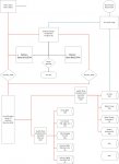
The AC power seems to be connected to the DC power bus.
Your batteries are connected together in series (24v)...is that what you intended? The (-) side of the second battery is not connected.
The second battery is not part of the load equation.
The circuit breaker on the left side of the diagram is correctly installed between the battery and the load.
The circuit breaker on the right side bypasses the battery and is connected directly to the load from the charger. You might check the specs, but most battery chargers have built-in circuit breakers for short circuit conditions so that would just be redundant.
The ground (-) sides of the circuits are mostly missing.
The 187 series circuit breakers that you mentioned are not called out in your drawing (unless they are the two 200amp circuit breakers that are showing). If so, you list the circuit breaker capacity at 200 amps, but the largest of those 187 series is only good for 90 amps continuous...?
Regarding the larger question of whether or not those 187 series circuit breakers could be suitable as switches (too) and avoid having a separate battery switch... I would have to say a qualified YES.
The caveat is that you should to place the two switches in close proximity to each other. That way you'll be sure to have selected the correct combination of batteries for your particular needs at the moment. From that set up, you can pick battery 1 or battery 2 or both battery 1 AND battery 2 combined into the load.
Regards,
RestorationRides

Sent from my REVVLPLUS C3701A using Tapatalk