AT IT AGAIN: Paul and Mike Convert a Mid/Tall T1N Sprinter Cargo

ben2go

Adventurer
Just this thing made from a Hobie Cat and a canoe...

1656168_10152165868007398_237056613_n.jpg

Very interesting.She should be able to take a lot of weight.
 

PaulJensen

Custom Builder
#9

P1040590.JPG

(above) With the roll-up doors built, the guides for the tambour needed to be designed...I made a small test strip of tambour to figure out the curve at the top...

P1040591.JPG

(above) The lines will be something like that...The dashed red line represents a cut that needs to be made at the top plywood on the cabinet...

P1040592.JPG

(above) The router guide pattern is ready...

P1040596.JPG

(above) Fourteen side pieces are needed...Before routering, the straight cuts on the plywood pieces were made on the tablesaw... A plunge router with a guide collar finishes off the curved cuts...Below the plywood is a piece of sacrificial styrofoam...

P1040593.JPG

(above) Next, the frame/platform for the bed to go above the cabinet/fridge on the curb-side was built...1/4" bottom, 1/2" sides...Box joints in the corners...

P1040594.JPG

(above) The pad in the frame...

P1040595.JPG

(above) With the curb-side bed size settled, the final design for the driver-side bed/sofa was plotted out...The curved toe kick will expand the feel of the narrow 'hall' down the center of the rear cabin...

P1040598.JPG

(above) To make the curve at the front, a round cardboard concrete form was cut on the tablesaw...The inside of the form has a wax saturated layer that peels off easy...Without peeling, the epoxy would not stick to the cardboard...

P1040599.JPG

(above) The cardboard quarter round pieces and a piece of 1/8" plywood were put in my curve laminating form...The same one used for the upper cabinets...

P1040600.JPG

(above) Epoxy resin and two layers of 4oz. fiberglass cloth...

Tomorrow that will get popped from the form and the rest of the bed/sofa platform will be built...

I'm really having fun with this build...!!!...
 

PaulJensen

Custom Builder
#10

Progress has moved along fast for the complexity of some of the details...I'm stoked to be this far along...Onward...

P1040601.JPG

(above) The bed/sofa platform...Really early in the day...A rough layout of the plan...

P1040602.JPG

(above) A screw box works as a mock inverter...

P1040603.JPG

(above) I shot these then sent them to Mike for the benefit of both of us...The internet is great for "now I understand" moments, again for the benefit both of us...

P1040604.JPG

(above) Day's end...Much more unseen than seen...

P1040605.JPG

(above) It always seems to be a challenge, space wise...Even in a Sprinter...Meeting the clients wishes and the reality of size constraints and failure points of materials, keeps the design process always in play....

P1040606.JPG

(above) The desired mattress height is 17"...The mattress is 5" x 30" x 73"....Something Mike found at Ikea...It's nice...

P1040607.JPG

(above) The movable bed platform for the curb-side...It stores under the sofa/mattress then pulls out (with a camping pad on top), then lays on the curb-side cabinet top, supplemented with straps to the ceiling mounted strap hangers...

Mike and I had a bit of a 'go round' with this design...His concern was the deeper rim of my design would be an annoyance with his overhanging arms when sleeping...My concern was the reduced frame size would be too weak...

Another consideration is spatial...The area under the sofa/bed is limited in width to fit the frame...It just is, as I'll explain below...

To meet all those considerations the rim was reduced from my preference of 2" to 3/4" at the back and 1.5" in the front...To strengthen this bed frame for an adult male, I'll use carbon fiber 'tow' along the outer rim...You'll see...

P1040608.JPG

(above) At the rear is a 5" plywood rim...A six foot piano hinge will be attached to that and to a piece of 1/2" plywood...That's the bed/sofa mattress support...There is a three sided 1/2" plywood, platform support rim...The rear rim with the hinge, is a multiple 'box beam' of plywood to stiffen up that rear edge...

P1040609.JPG

(above) The rim at the back is 5" wide, the same thickness as the mattress...In use, to access the curb-side bed, the mattress is lifted flat to the wall...The plywood bed/sofa plywood platform is lifted, clipped up, then the curb-side frame is removed and placed on the curb-side cabinets, then the bed/sofa is lowered and everyone goes to bed...

That 5" mattress depth is a limiting factor on the bed platform design..So is the 30" bed width...So is the camping pad size (all dimensions)...So are the physical strength properties of the plywood...Weight is a factor too...Client comfort concerns are also a consideration...So is the desire to have maximum storage under the bed...Given those parameters, that is why the removable bed platform is as it is...

P1040611.JPG

(above) The bed/sofa ply platform is laid in there...Still need to hinge it...

P1040612.JPG

(above) All along, the mattress pad thickness was accepted to be 2"...Perhaps as thin as 1.5"...Mike noted it several times in the drawings as that...I even unrolled it, opened the vent and in a few minutes I measured it to be 2"...Cool...Well after it set out for a day, and I finally read the model number as '3.5', it turns out the pad really is 3.5" at full inflation...Oh my...

P1040614.JPG

(above) That's not what I expected to see once the pad was in there...So, I called Mike and he walked me back from the edge and said "No worries, I'll deflate the mattress just before I get up in the morning" then, "If it's still to thick, I'll get a thinner pad" ...I offered to adjust the cabinet to make it work but Mike said 'leave it"...Thus ended the day...

Tomorrow, the drawers start...
 

PaulJensen

Custom Builder
#11

Since I last posted, Mike has returned the van, the tambour doors were fitted in the upper cabinets, the 'table-in-a drawer' was designed and tested, the upper cabinets got more fiberglass reinforcing, and the kitchen design and build is close to completion, and the paint progress is well underway too...

A few photo's to explain...

P1040615.JPG

(above) Upscale Automotive in Portland did the heavy wire work...This is how it looked when it was driven back up to my shop...I'll do the final positioning later, after the mock up bed is out and the permanent bed is in...

P1040616.JPG

(above) The Electrical plan...

P1040619.JPG

(above) At the foot of the bed there is the sink/kitchen cabinet...This is the end-panel of that cabinet as it will face the bed/sofa...Recessed into the cabinet side panel are the circuit breakers, both AC and DC...The square cut-out is where two 110V AC outlets will go...One will be dedicated for a heater or air conditioning unit, the other will have powered USB ports built into the 110V outlet...The round thing is for monitoring the 12V DC system...At the bottom on the right is a wheel-well cut-out and on the left is an access panel to the inverter from inside the kitchen cabinet...

P1040620.JPG

(above) The first of three coats of oil base primer is on both of the wall cabinets, and the lower curb-side cabinet...Lots of sanding and puttying preceded that...

P1040621.JPG

(above) The kitchen cabinet face without any cut-outs in it...The rectangle space on the left is where the microwave oven will go...

P1040622.JPG

(above) Again, the electrical end panel...Mike wanted the switchboards to be recessed to prevent accidentally switching things, and he wants a sliding smoked plexiglass panel to keep the indicator lights on the switchboards from being a distraction...Here a plywood panel is fitted to see how it works...Below that, the pencil lines represent the bed frame height and the mattress pad height...I ended up re-doing this panel once to get the clearance right...As always, things are tight...

P1040623.JPG

(above) Sliding panel up...

P1040624.JPG

(above) Sliding panel mid-way...

P1040625.JPG

(above) Inside it looks like this right now...The breakers are positioned to be just below the bottom of the sink for service and inspection...You can also see where the sliding panel goes up into...Below the breakers is a plywood wheel-well cover / attachment panel...

P1040626.JPG

(above) On the rear door side of the cabinet it looks like this...The access door is as big as possible...Above the opening is where the microwave oven is...The water heater final placement is still being though out with the custom blue and grey water tanks being a huge determining factor on final positioning...

P1040627.JPG

(above) The view if you were standing on the step-bumper...Again, there are cut-outs in the front face still to come...

I have appointments with the solid surface fabricators this week...The sink will be a solid surface under-mount...There will be another countertop next to the fridge and my 'table-in-a drawer' will also be a Corian like product...

Also being finalized are the fabrics to upholster the bed/sofa and the back-rest pillow cushions...The curb-side seat also needs a cushion and a pair of back and side cushions too...

Oh yeah, the special order flooring is in too...Still need to pick it up...

As you can see it's moving along fine, I just haven't been picking up the camera as much...

Finally, congratulations to the World Champion Seattle Seahawks for doing what they said they would do...!!!...
 

mhiscox

Expedition Leader
Mike I would love any and all info on the house battery system you had installed!
The battery bank installation predates my ownership of the truck, but that's largely a good thing, as John Bendit and his fabricators at Upscale did a much more sophisticated install than I'd have ever attempted. John used three Group 31 Odyssey absorbed glass mat batteries with 20-hour capacity ratings of 100 amp-hours each. So I have available, given the maximum recommended 50% state of discharge, (3*100)*0.50 = 150 amp-hours of usable capacity. If I was installing the banks from scratch, I'd have probably chosen the same batteries--Odysseys are one of the brands I've had good luck with--with the same form factor and capacity, and I'd have probably aimed for about 300 amp-hours overall. So what I got just by happenstance was perfect for my eventual design.

But through lack of a lift, lack of talent and so on, I probably would have put the batteries within the van structure. But John and his group were able to put the batteries under the truck. It took lots of work and cleverness to do this, but it worked out great. Because AGMs can be mounted in any position except upside-down, that allowed the flexibility to tuck them around the underside of the truck without creating a ground clearance issue. They also had to be cleverly positioned to spread the weight around and to minimize the amount of (expensive) heavy gauge cable.

But far and away the biggest challenge was to mount the batteries so securely that they don't bounce around and vibrate when the truck is driven over crappy surfaces. You can probably imagine that holding a 75 pound weight immobile over something like a bad washboard surfaces would require some talent, and I'd have never even attempted it. But John and company built custom frames to hold each battery and then attached these frames securely to the truck. I'd take more photos if the truck was here, but this photo shows one of the batteries and its mount. (Note the differential in the lower right of the photo to show the relative ground clearance.)

attachment.php


Note, too, how the batteries also have front "skid plates" to protect from road debris.

Three Group 31 batteries use up a sizable amount of space, so while I could list a few downsides to having them under the truck, it sure is nice not to have them taking up the limited space on the inside. The batteries are seven or eight years old now, which should put them at the end of their life (though they still appear to be working great), and when they need replaced, I'll pay John to hoist the truck up and put direct replacements into the same mountings.
 

PaulJensen

Custom Builder
Yesterday it was mostly a tool-less decision making day...

First, it was a trip to the local RV shop to see who they would go to for custom sized water tanks...I had already talked to the sheet metal shop about it and got a price in the $300 range for something out of aluminum...After that conversation I researched building them myself out of fiberglass and epoxy resin...The resin I use turns out to be suitable for potable water...Good to know since that opened up the option of being able to truly do something extremely custom...Back at the RV shop, the guy behind the counter pulled out a catalog of polyethylene water and holding tanks...I was not expecting to so many sizes that they make on a 'as needed' basis...With the catalog in hand, I left feeling confident I'd be able to find something that would work, without having to go the custom route...

Next, it was off to the upholstery shop...I had been working hard to have the basic cabinets built and loosely placed in the van to make deciding fabrics and colors easy to visualize with the spaces defined...At the upholstery shop, I met with an interior designer who I've worked with before and really respect and the in-shop fabricators...Sample books were gone through, fabrics were looked at in various lights, 'double-rub' data was considered, as was washability...I had the ceiling material settled on already...It's the same stuff as the front-cabin headliner shelf I made...Mike found a carpet floor tile that I agreed was a great choice...All that needed to be decided was fabric for re-covering the bed / sofa, the bolster cushions, something for the wall behind the bed / sofa and foam and fabric for the curb side seat...The decisions came quickly and will look 'enriching'...The upper and lower cabinet colors were decided too...They are a touch warmer than my first choice of industrial greys...A deposit was paid and we are on the production calendar...Hopefully that means we get everything ready to install in the first week of March...

Finally, it was back to the shop to fine tune the measurements and placement options for the blue and grey water tanks in the kitchen cabinet...With the tank catalog in hand it was simply finding a pair of tanks to fit...There were only two obvious choices after going through the endless pages of options...The blue water tank will fit on the floor (best for weight distribution and easy to secure) and the grey water tank will fit atop the wheel well...The tanks are made by Pellandent/...The blue water tank is model # 09-RV68W with a capacity of 20 gallons...The grey water tank is model # 06-21521 with a 6.7 gallon capacity...I'll need to tap into the tanks to place the fitting, but that should be easy...At the end of the day I ordered the tanks and felt great that two huge decisions were in the rear view mirror...

Tomorrow, it's back in the shop to finish building the kitchen cabinet and painting progressing...Yeaaaah...!!!...
 

PaulJensen

Custom Builder
#12

P1040641.JPG

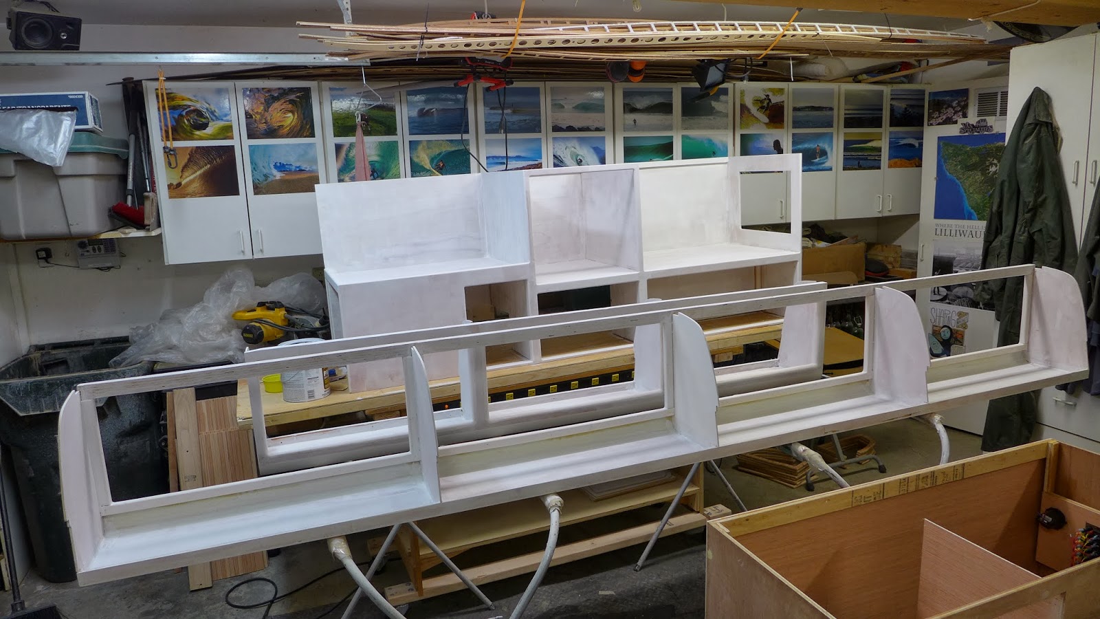
(above) The cabinets with the second of three coats of primer...Puttying and fine sanding between each coat, of course...

P1040642.JPG

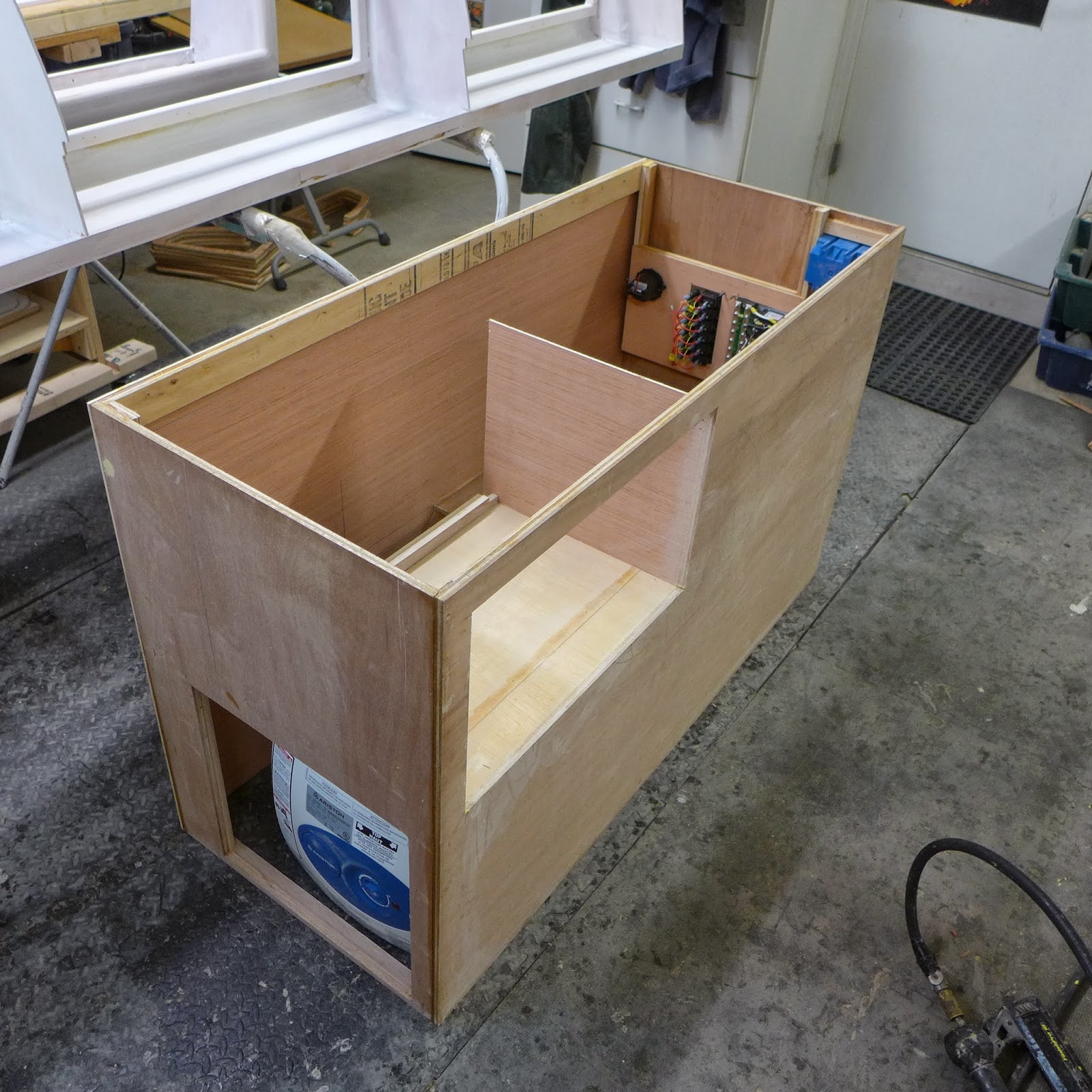
(above) The shadows tell of the complexity of the kitchen cabinet...

P1040637.JPG

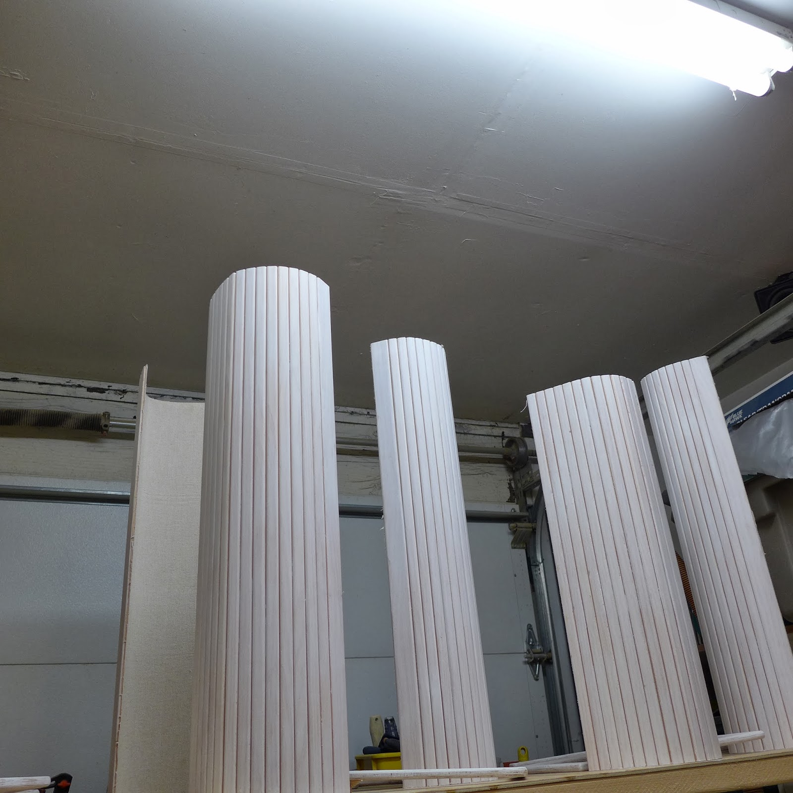
(above) In the shop, the roll-up doors and other bits get primed too...

P1040638.JPG

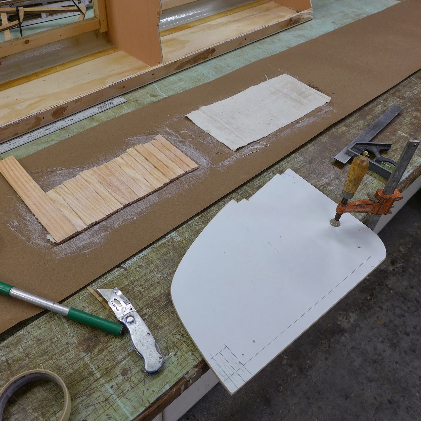
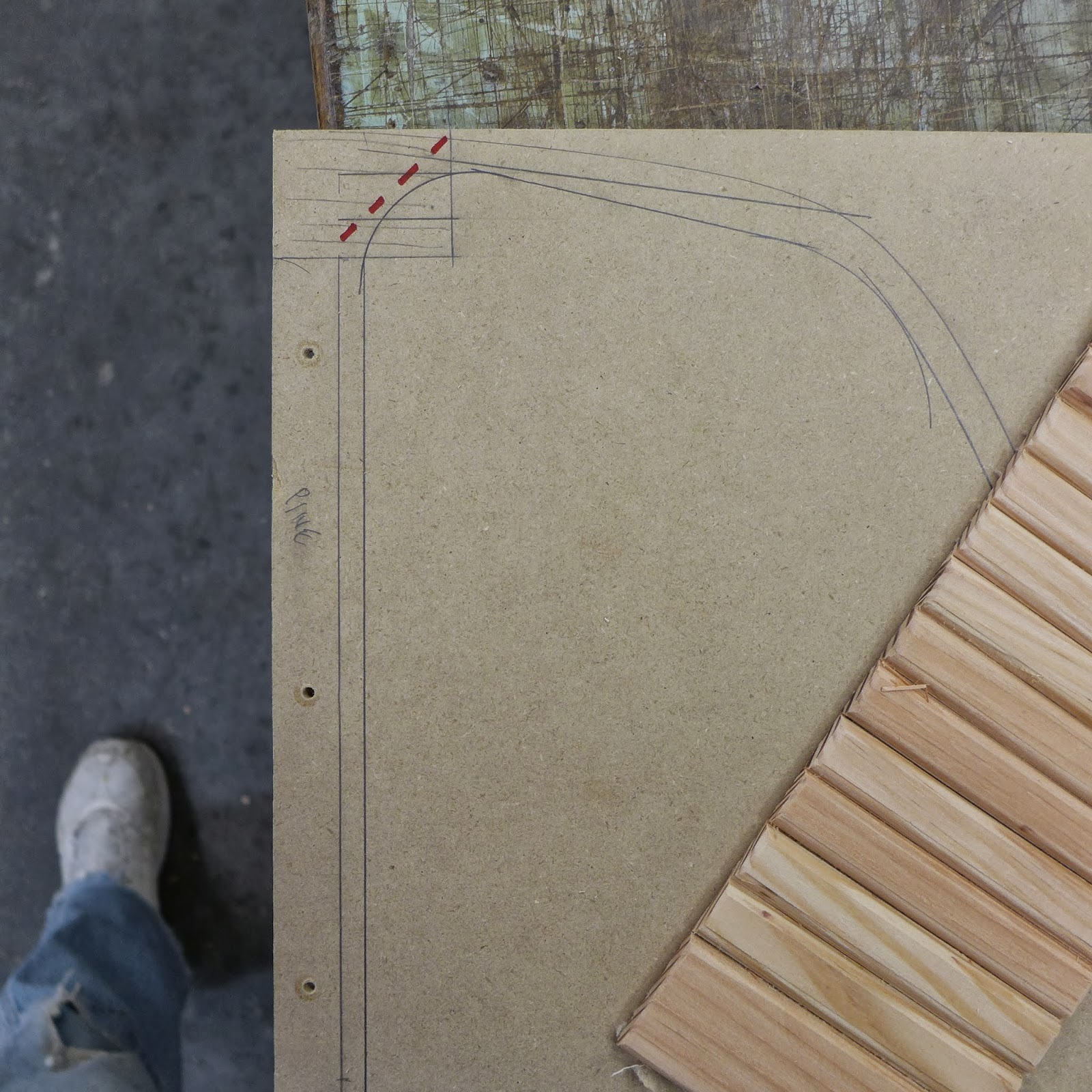
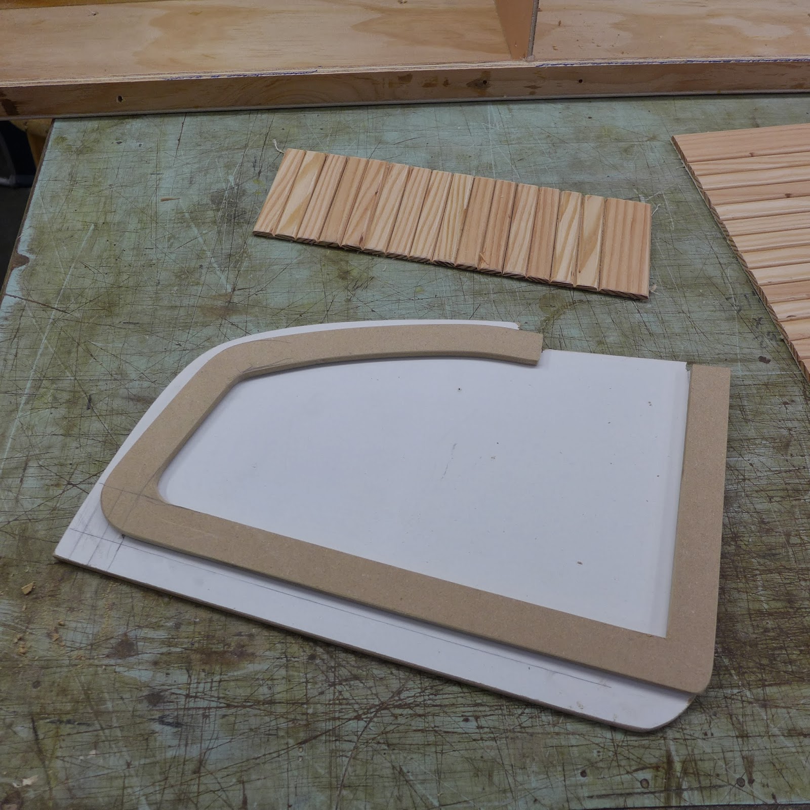
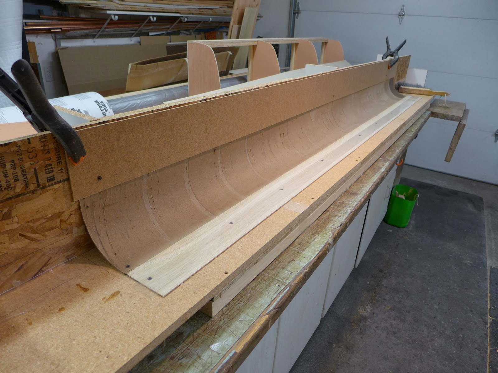
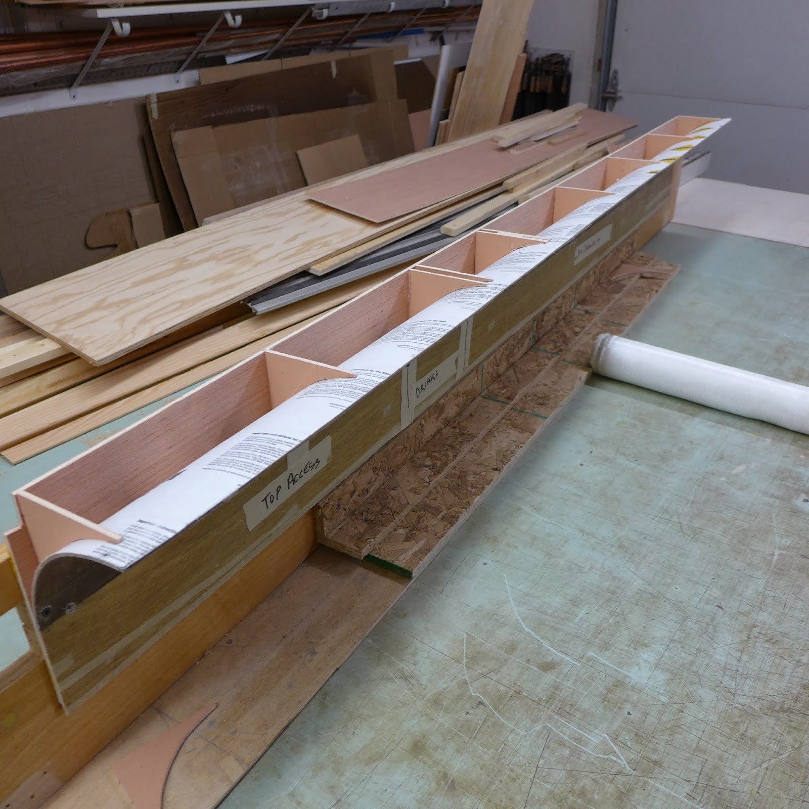
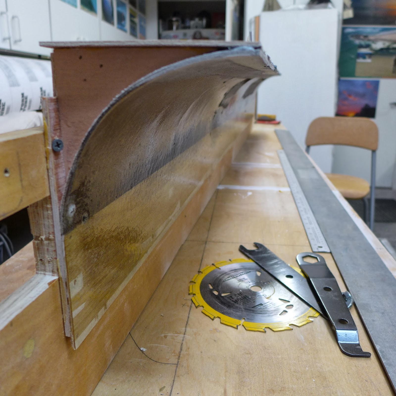
(above) The bed/sofa drawer faces, gets curve bracing hot glued to the plywood and the cardboard curve...

P1040645.JPG

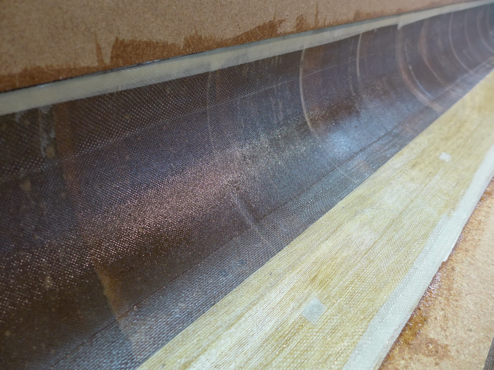
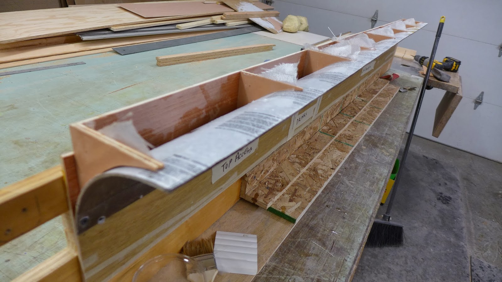
(above) ...then those get fiberglassed for permanence...

P1040648.JPG

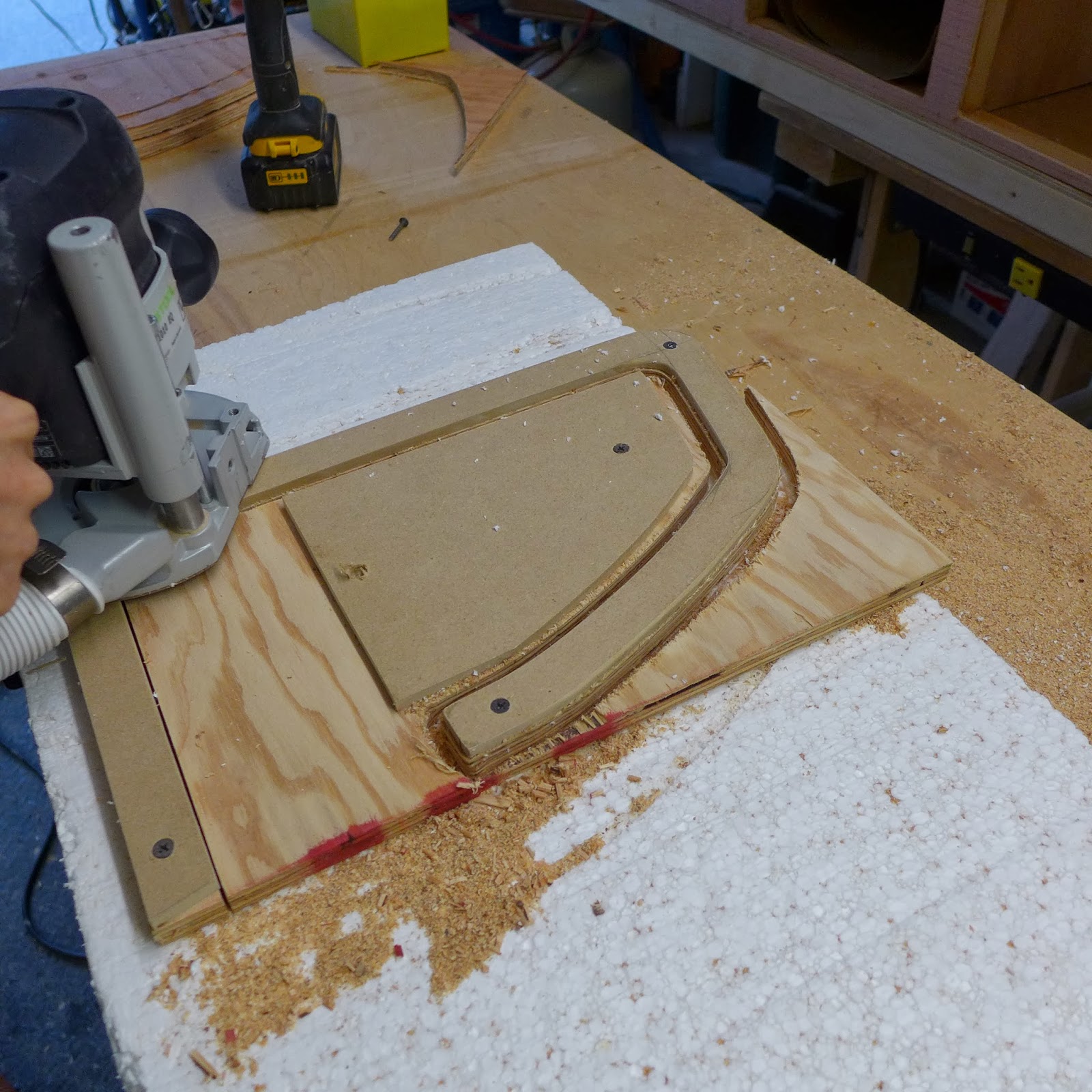
(above) The hidden drawer pull slots are routered out, then fiberglassed...

P1040649.JPG

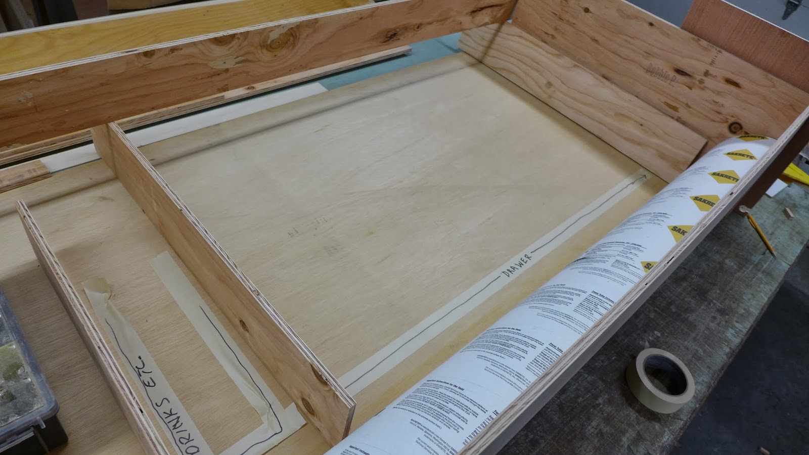
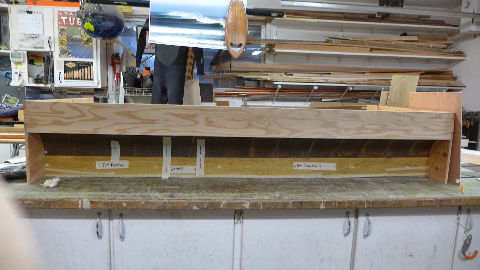
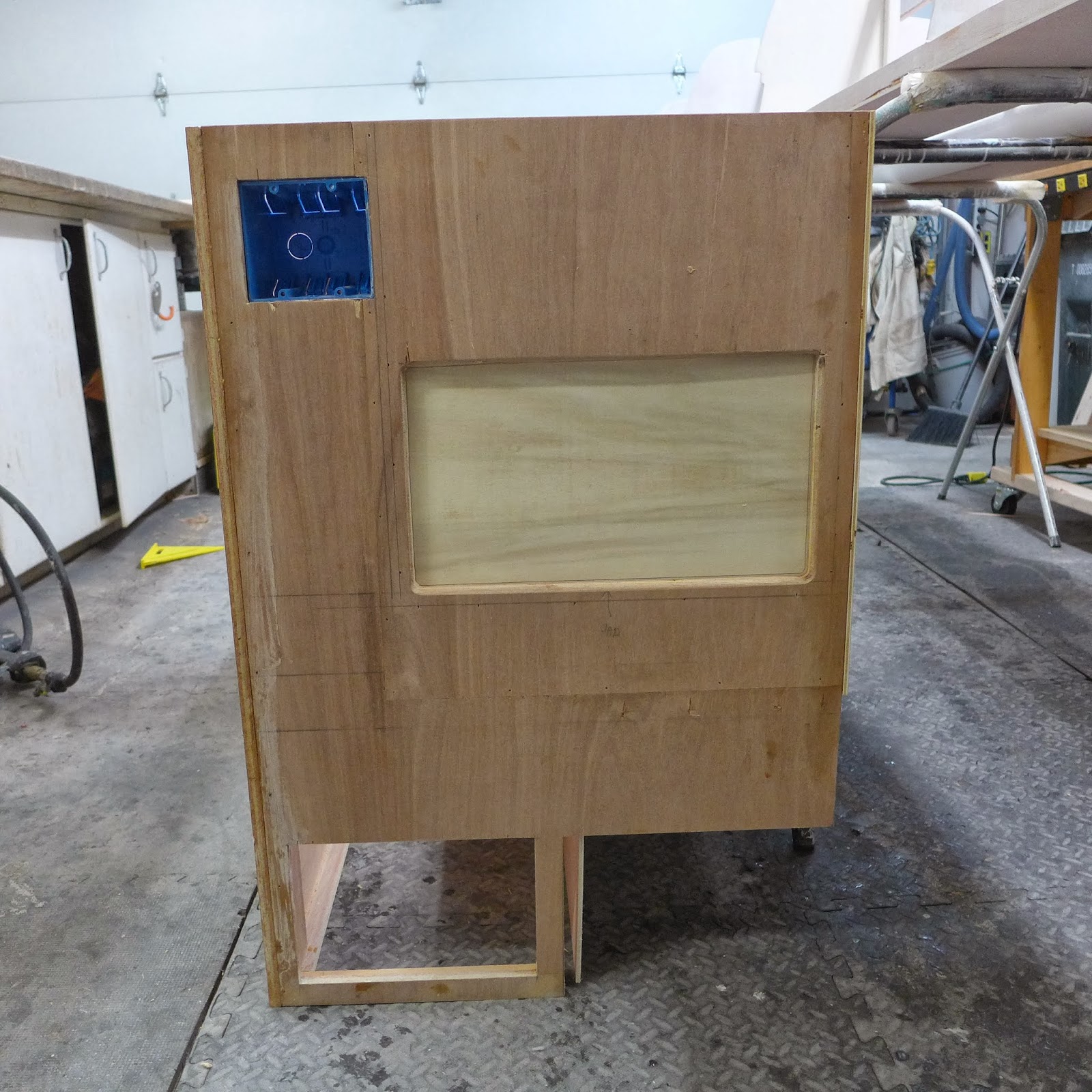
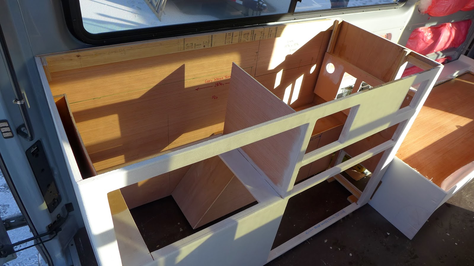
(above) Keeping the drawer faces/toe kick in one piece, before cutting it into parts, keeps everything aligned and straight...When it get's installed, the goal is to have it look close to seamless...

P1040650.JPG

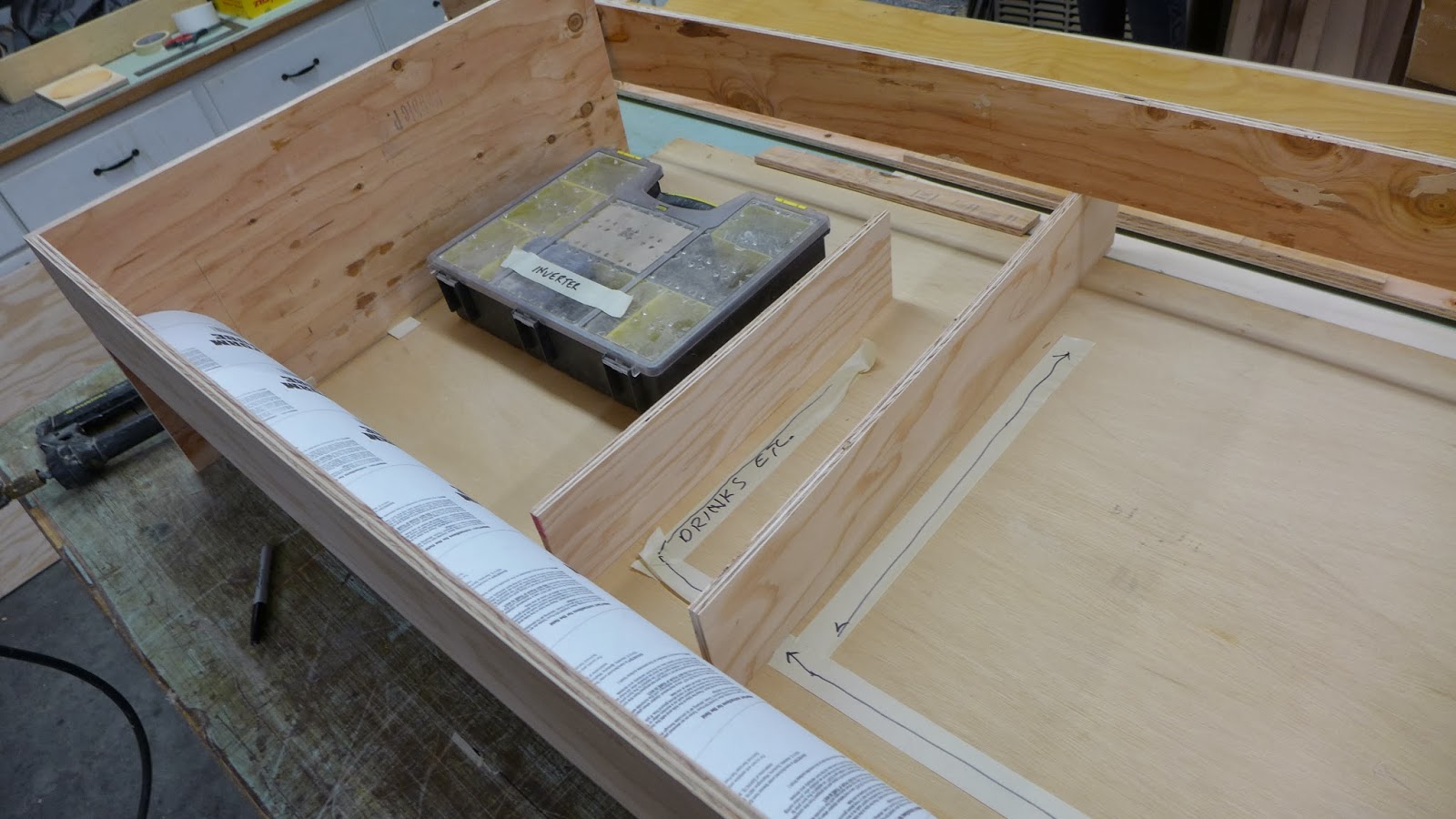
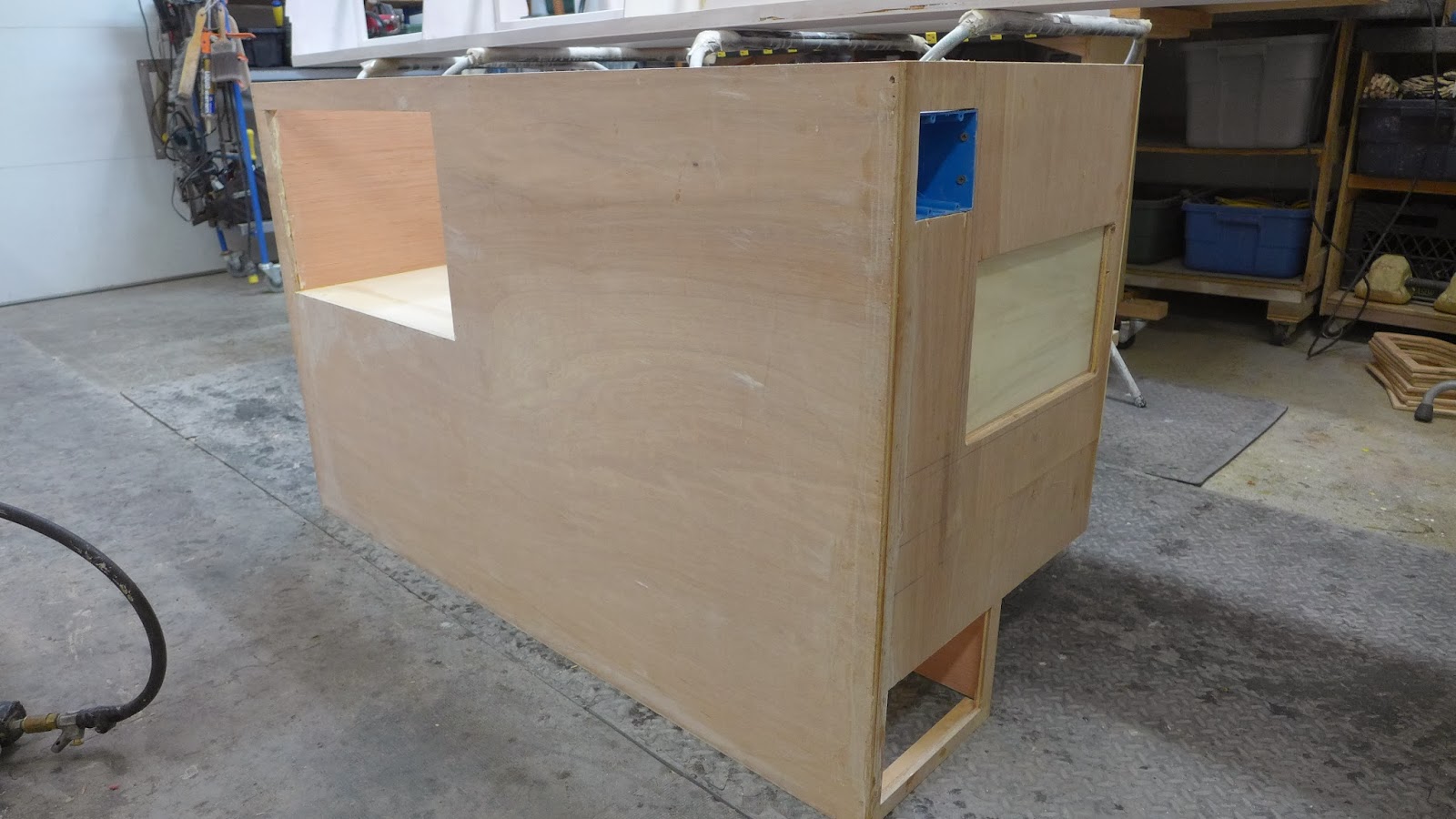
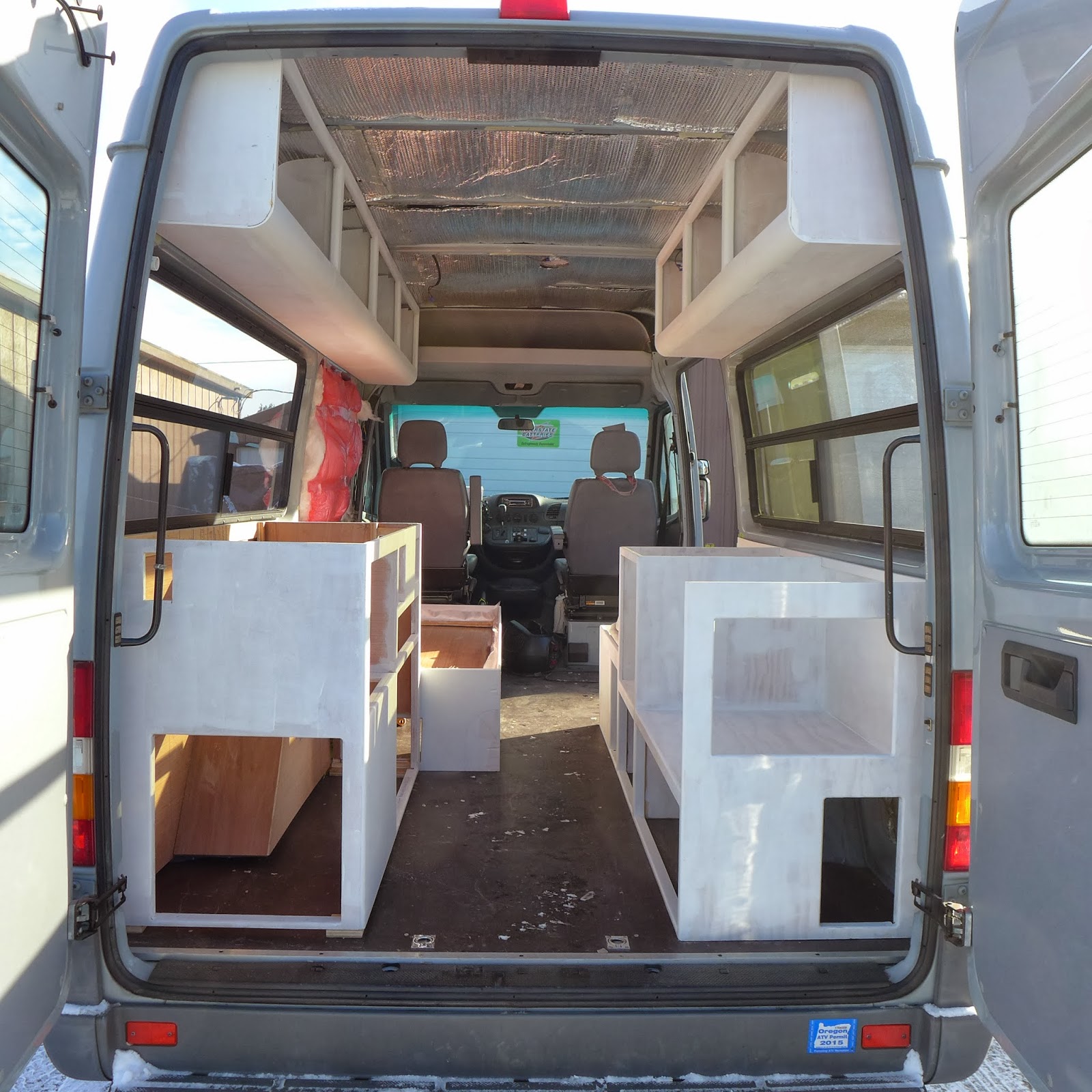
(above) This is the viewing angle when you are standing at the rear of the van looking in...The main reason for the recessed toe-kick is to gain foot space in a hallway that is about 17" wide...Doing it this way also visually expands that space...The little things matter when things get tight...

P1040661.JPG

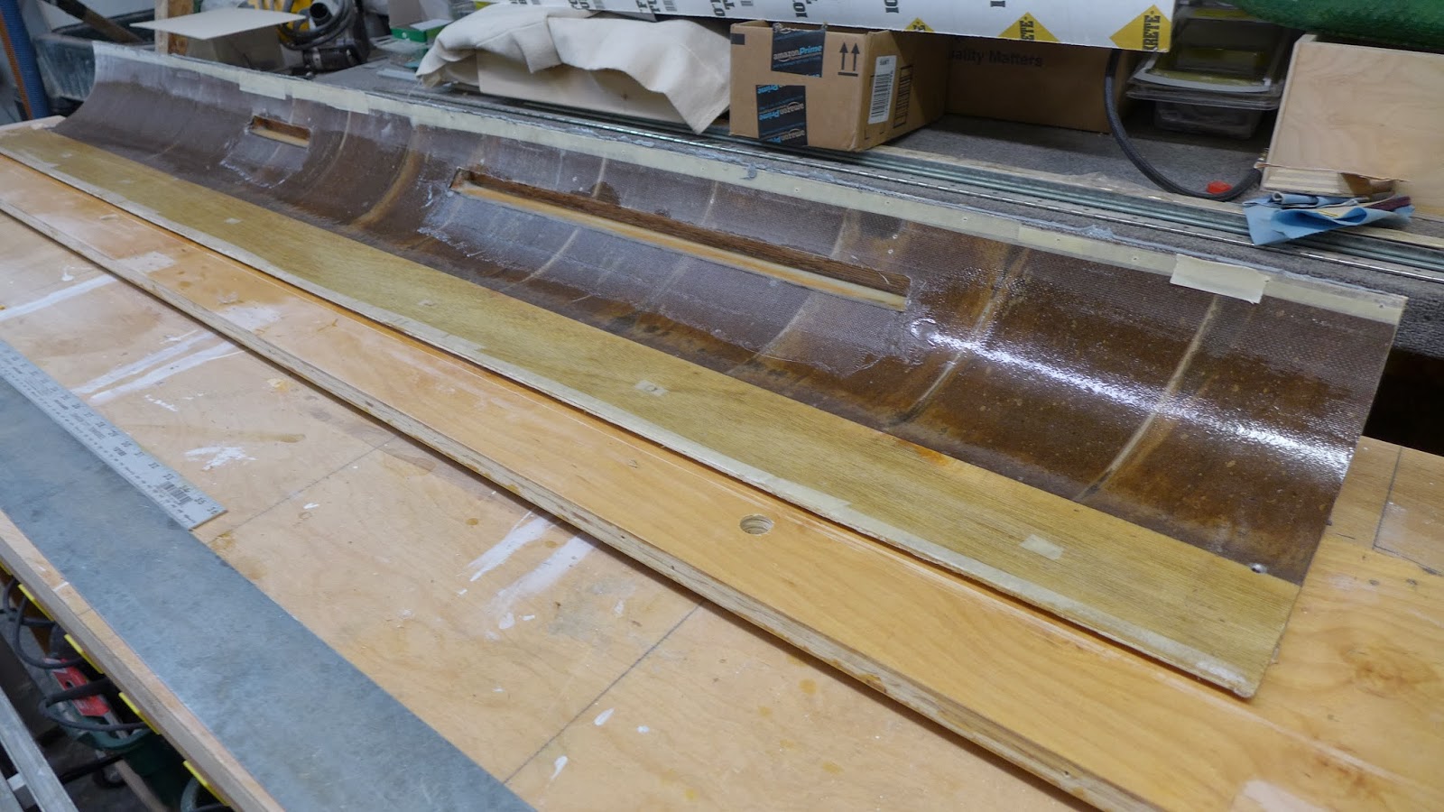
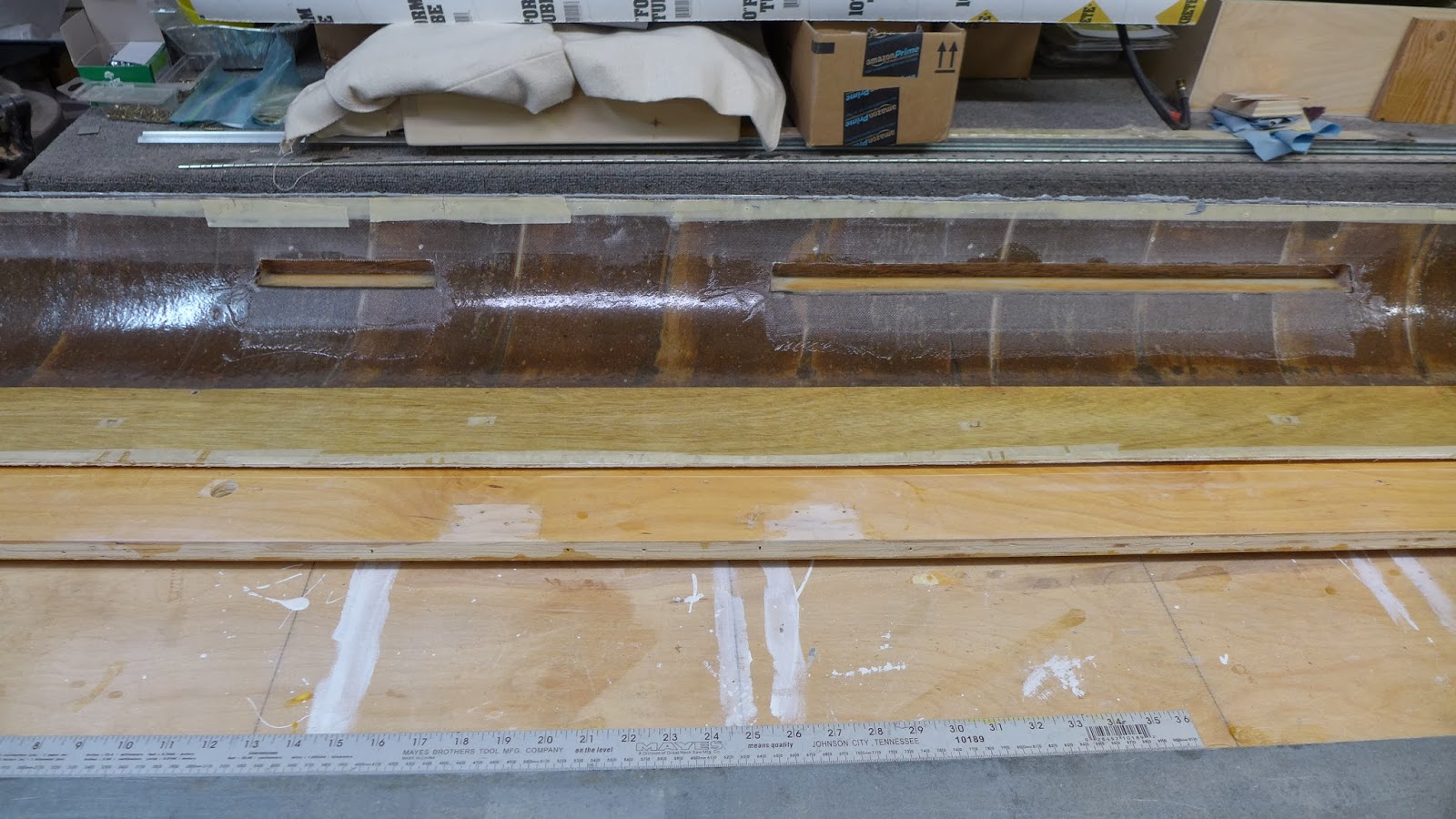
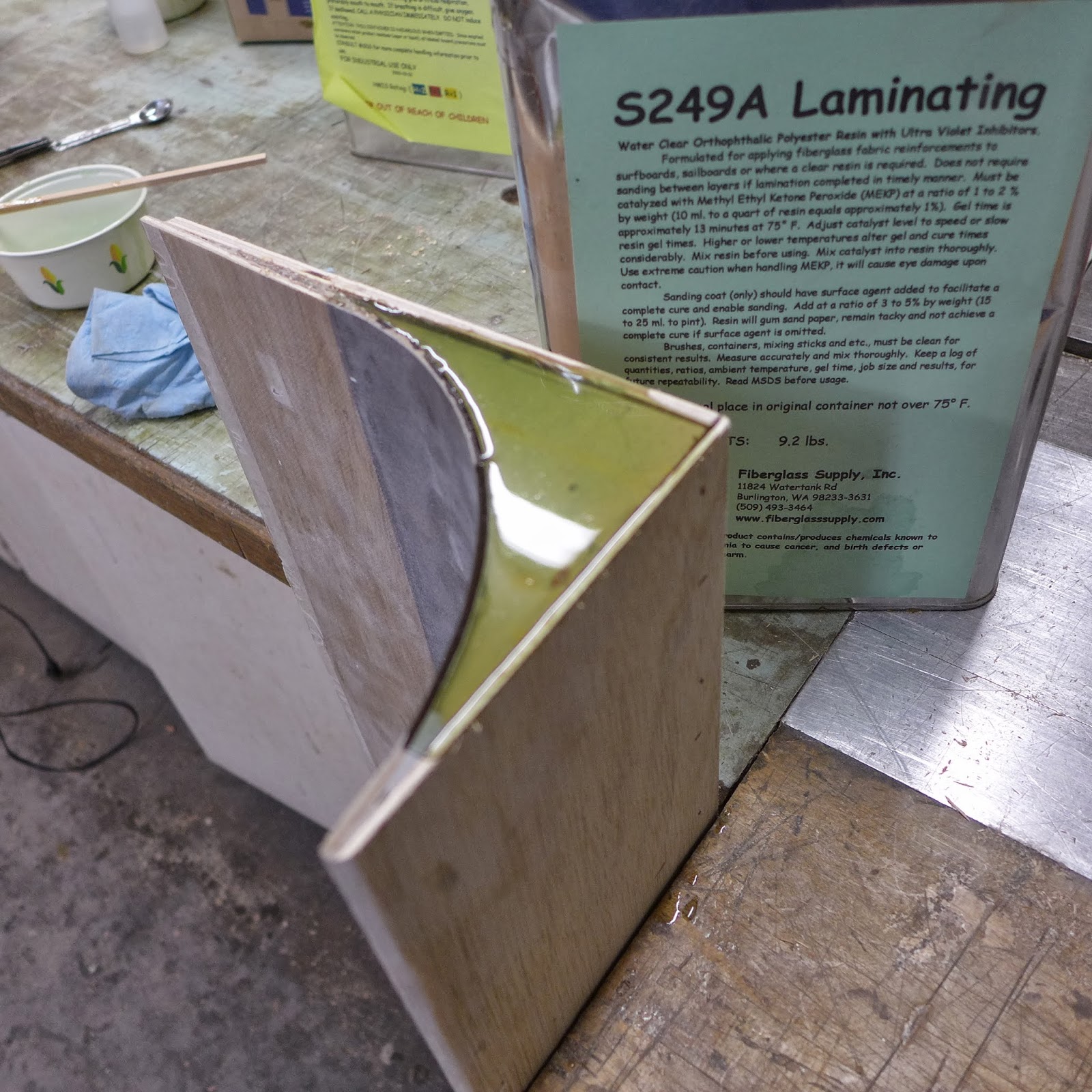
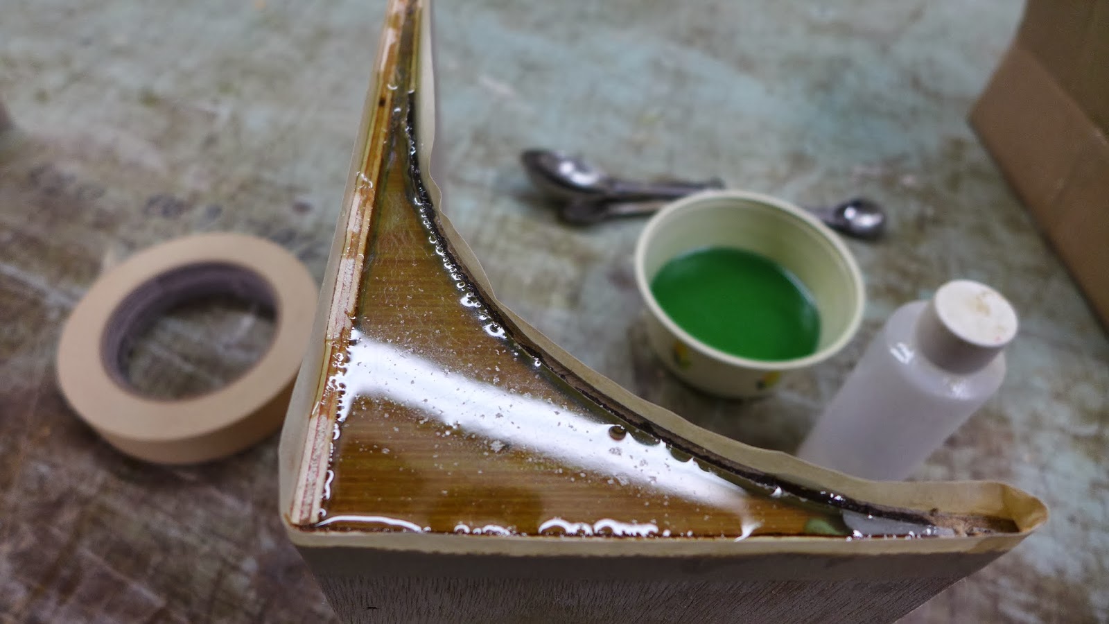
(above) The drawer face sections were cut apart on the tablesaw, then the ends were filled with some polyester resin...That will get sanded later...

P1040662.JPG

(above) Polyester resin is good for something like this since it goes off fast...Epoxy might take three or four times as long...Here, I'm looking for a fast setting filler, not kryptonite like strength...

P1040664.JPG

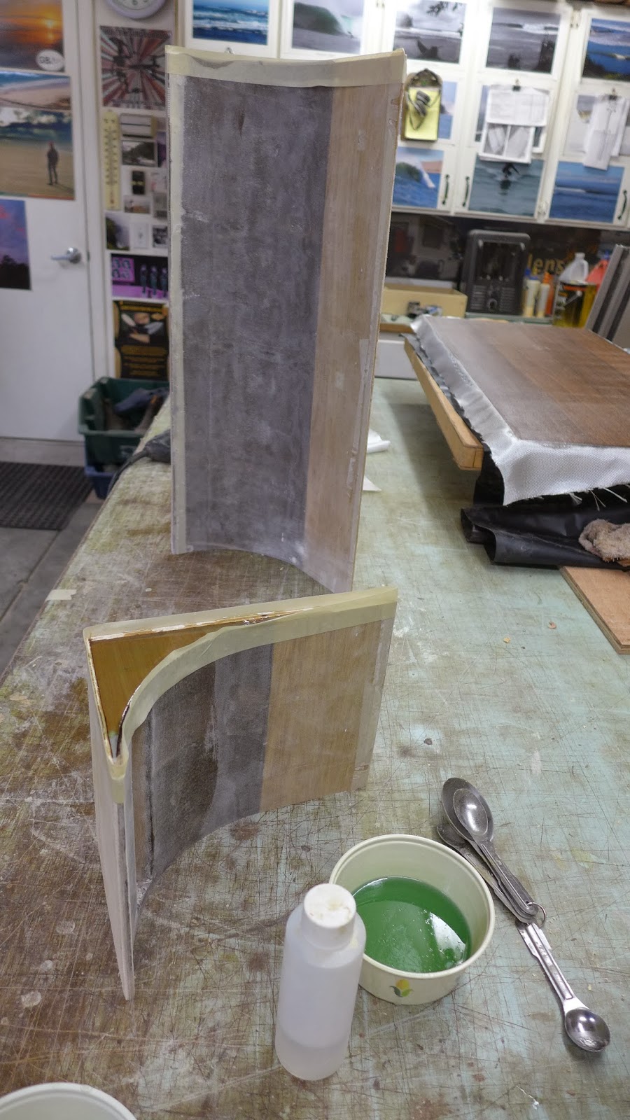
(above) Close to ready for primer...

P1040663.JPG

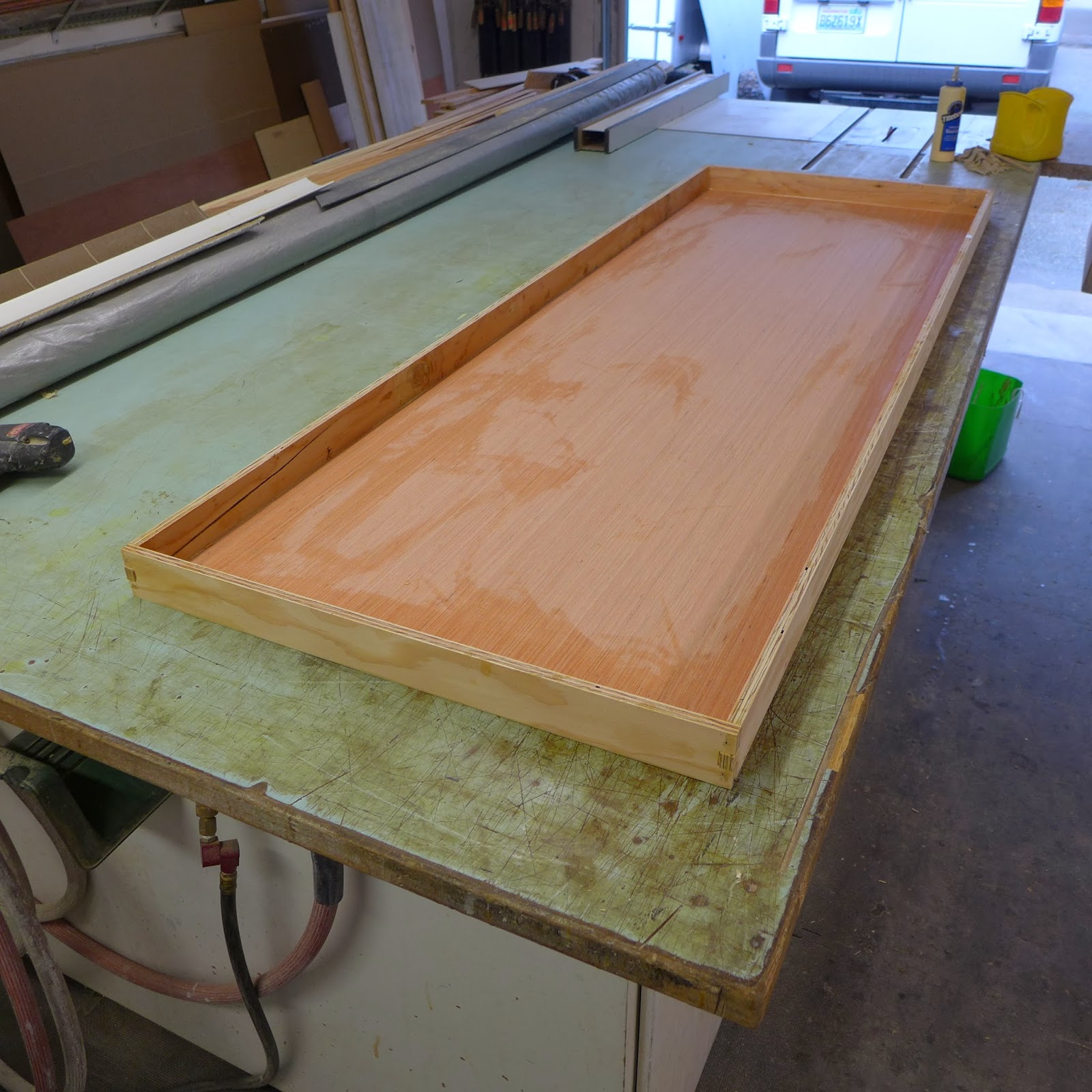
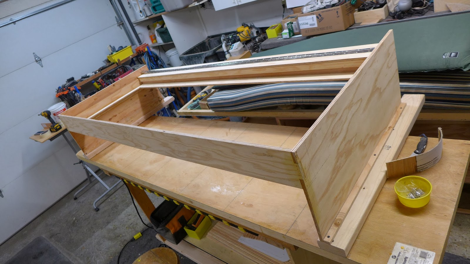
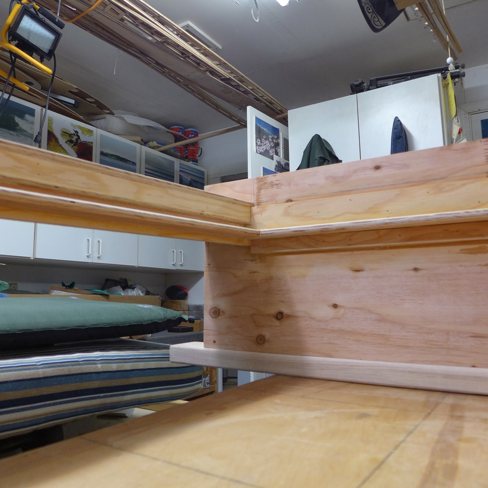
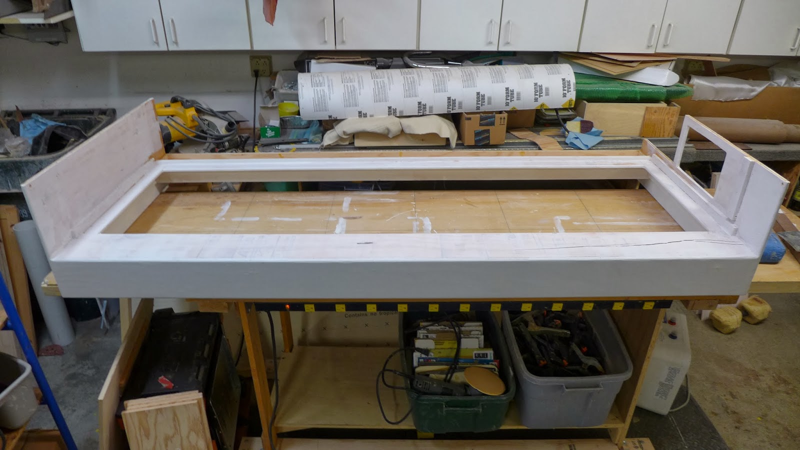
(above) The bed frame, upside down will get the drawers built and installed tomorrow...

P1040640.JPG

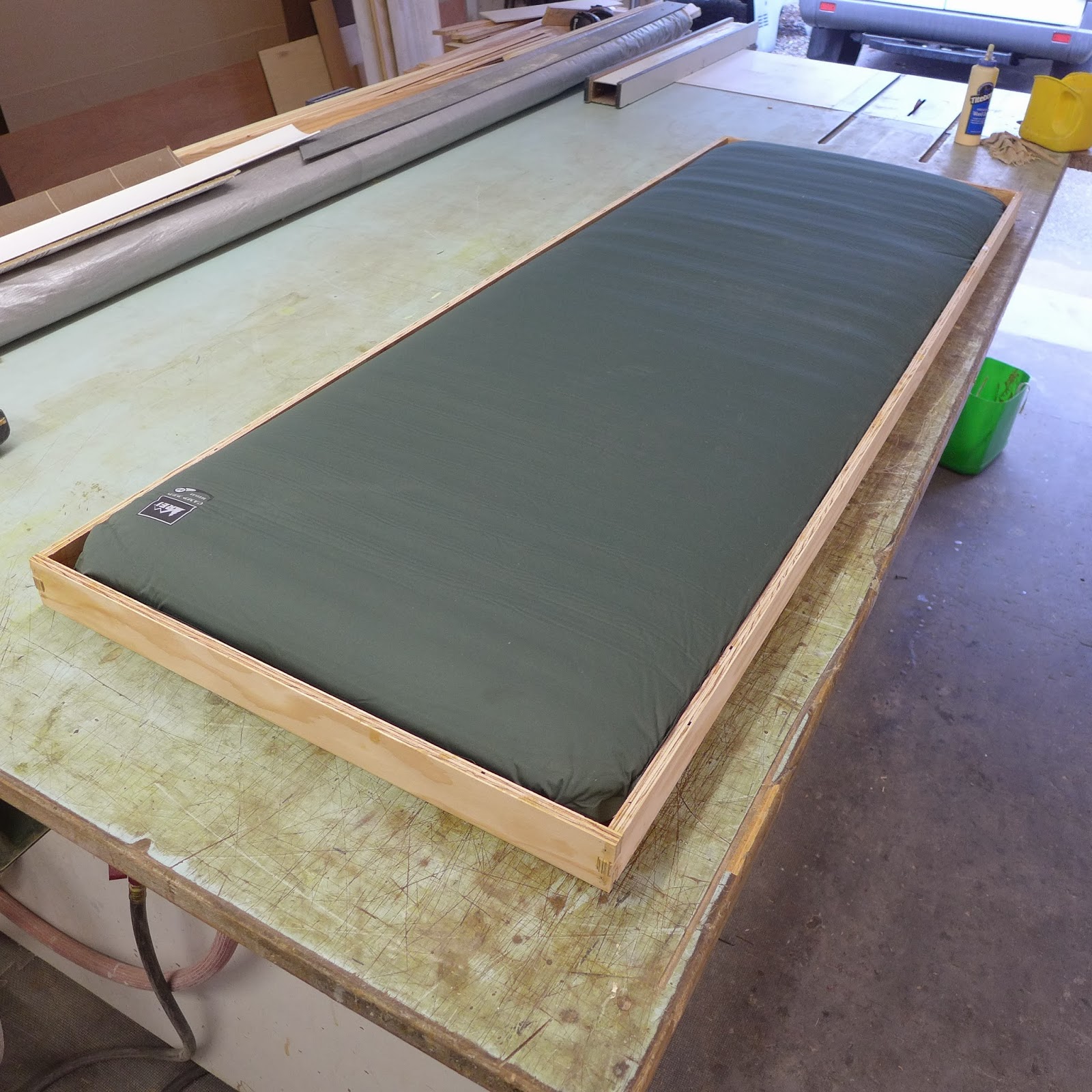
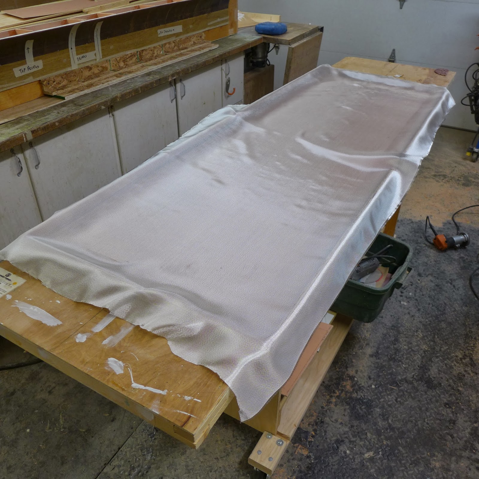
(above) The pull-out curb-side bed is lightweight plywood...To give it the strength is needs, it will get fiberglassed with 4oz. e-cloth and epoxy resin...

P1040639.JPG

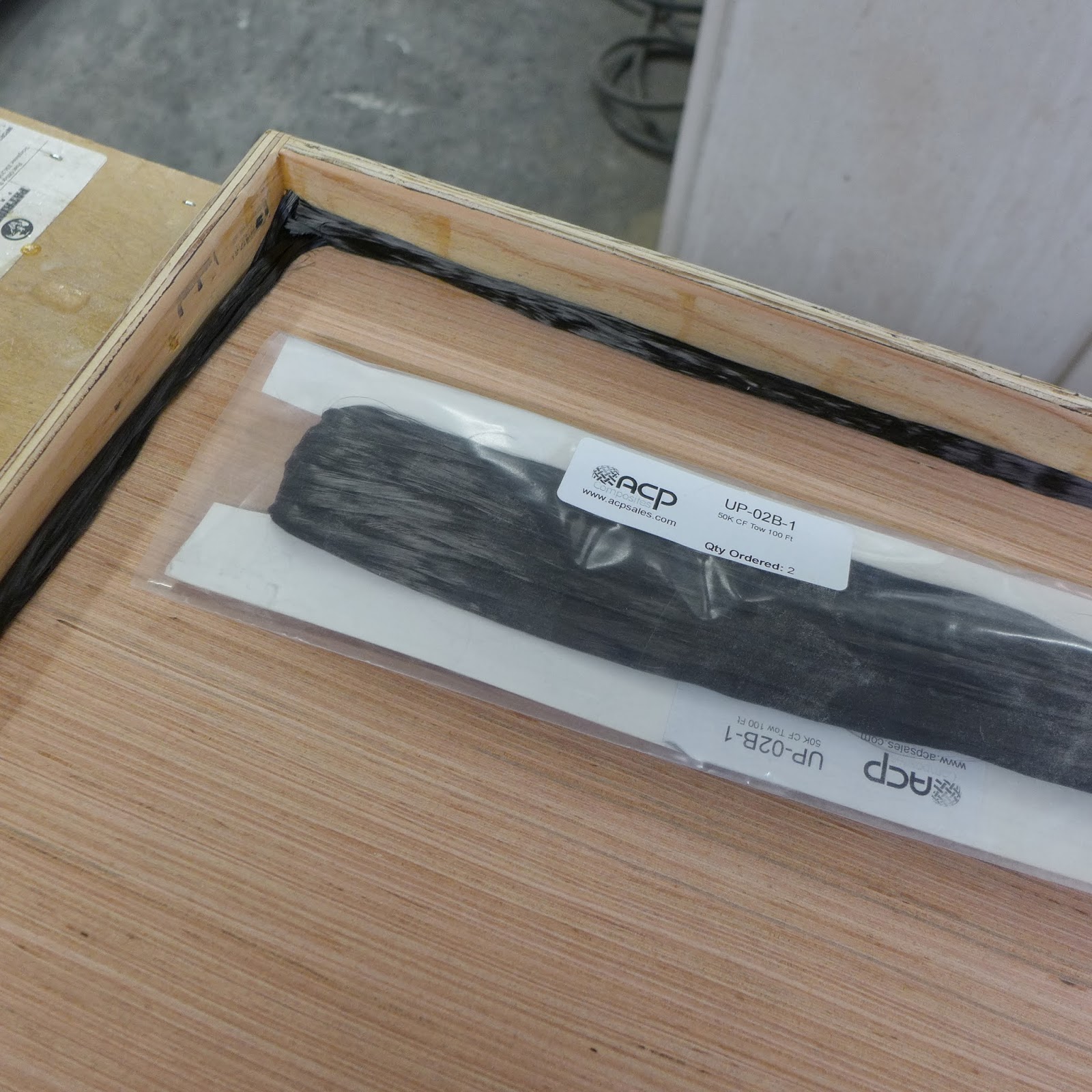
(above) The secret ingredient for strength is 'carbon fiber tow'...That black yarn there...

P1040646.JPG

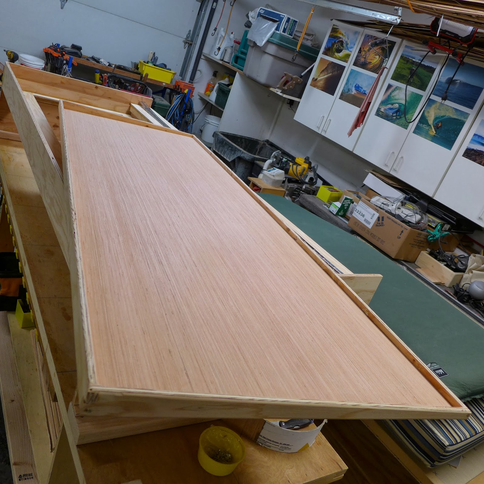
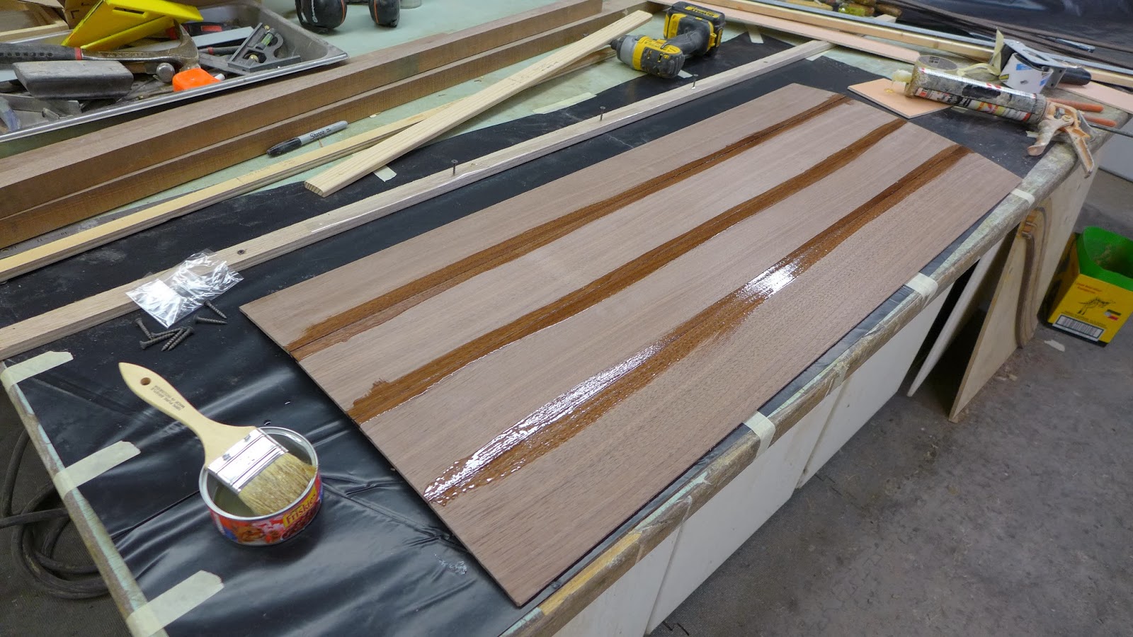
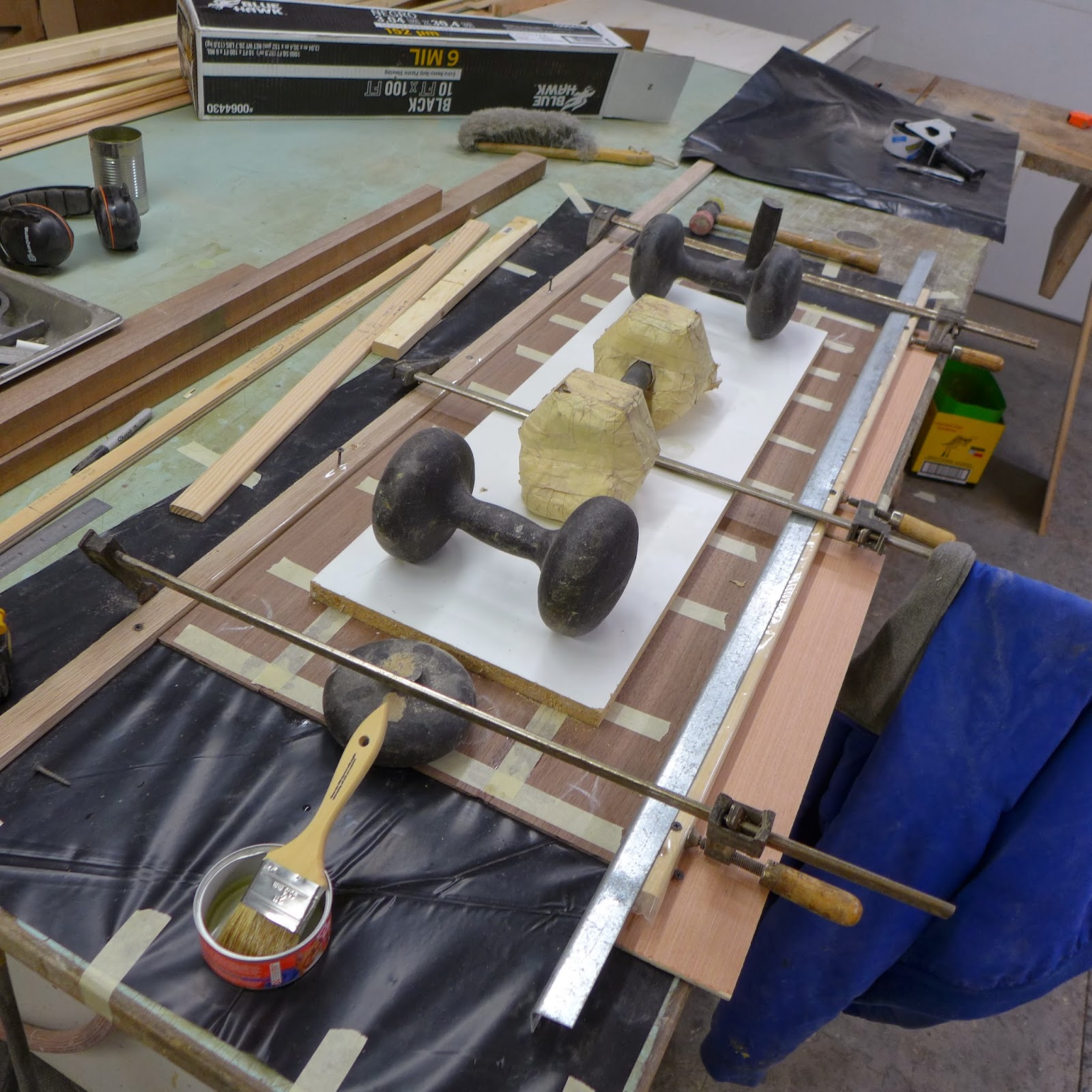
(above) Next on the list, the 'table-top in a drawer'...A 42" piece of walnut, 1.25" x 4.5" was cut on the tablesaw, then run through the planer at 1/4"...The wood strips were masking taped together, flipped over and epoxied together at the seams...

P1040647.JPG

(above) Clamps and weights keep it tight and flat...Thin wood can be a challenge that way...

P1040654.JPG

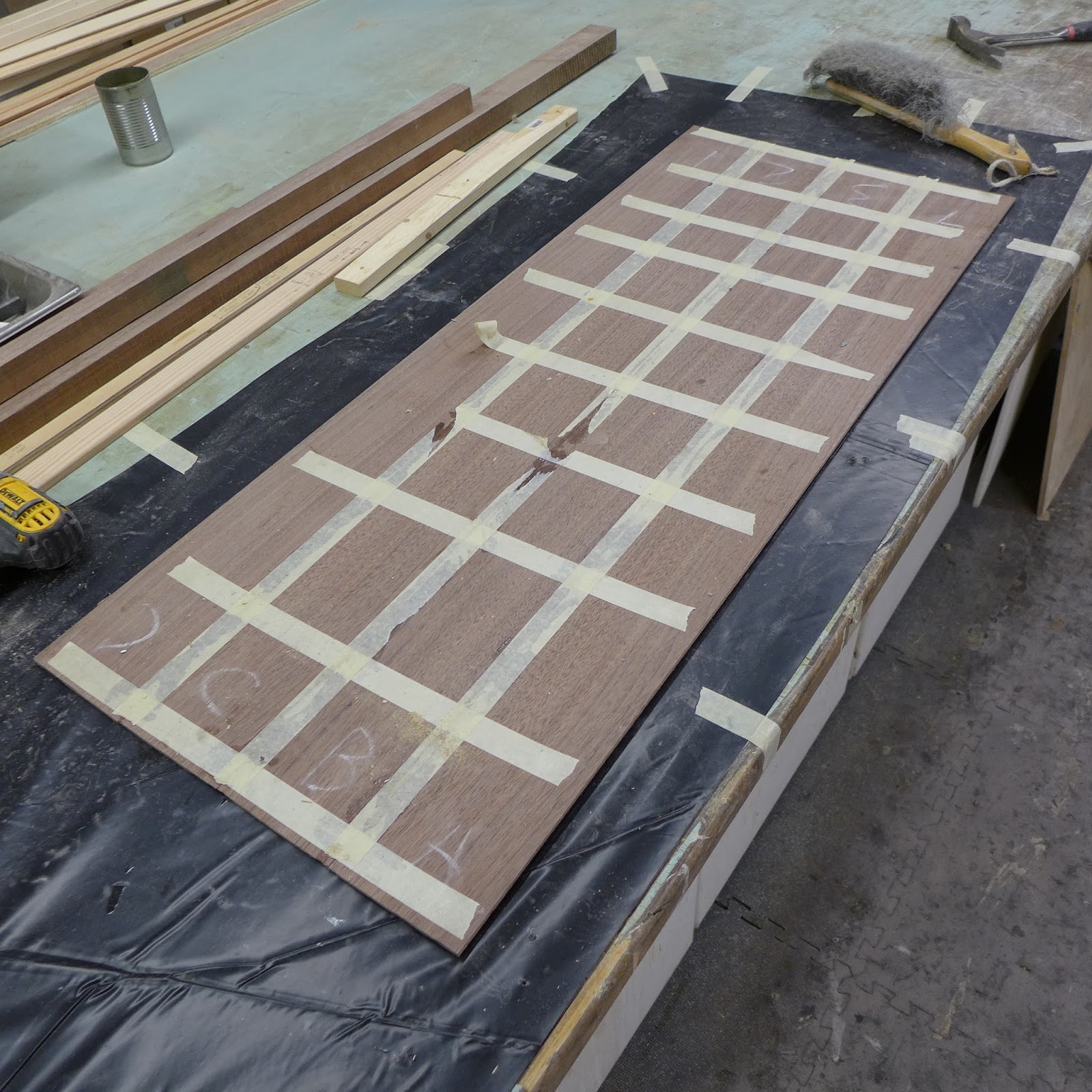
(above) The masking tape on the walnut panel is pulled after the epoxy had dried...

P1040652.JPG

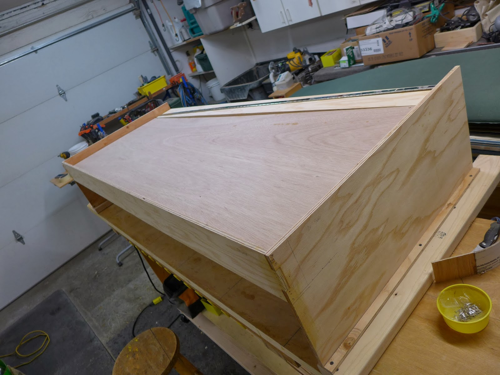
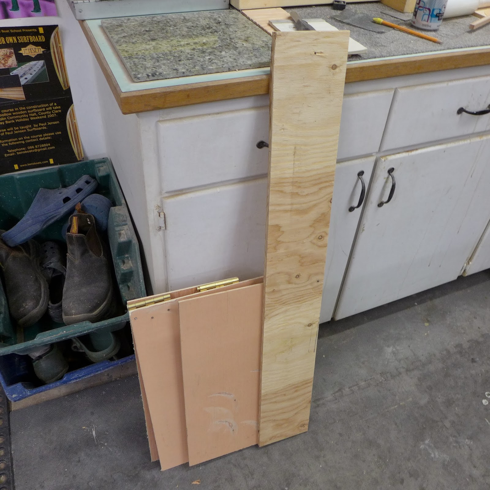
(above) This, is my pull-out table mock up...Crude, but it worked to validate the design...

P1040658.JPG

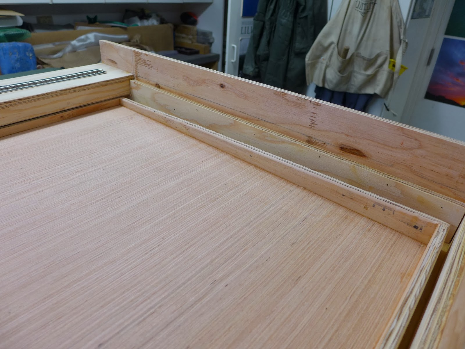
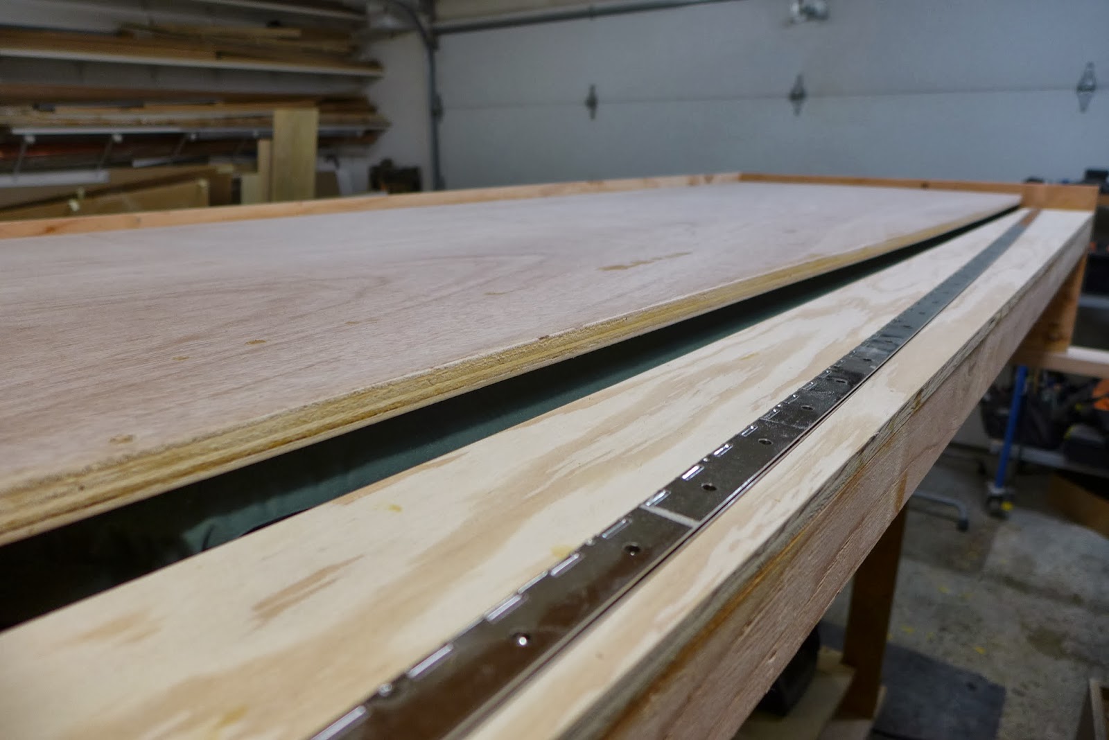
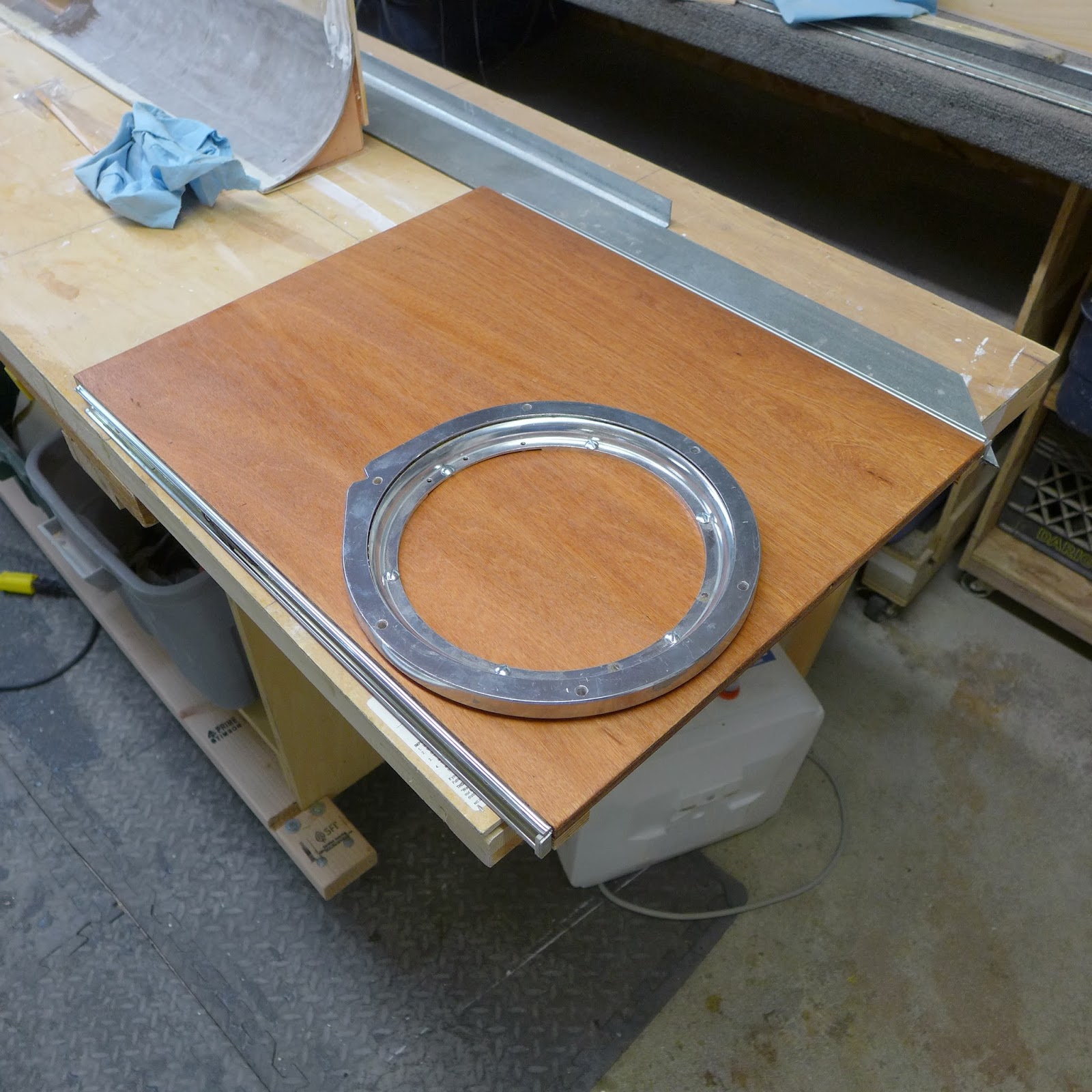
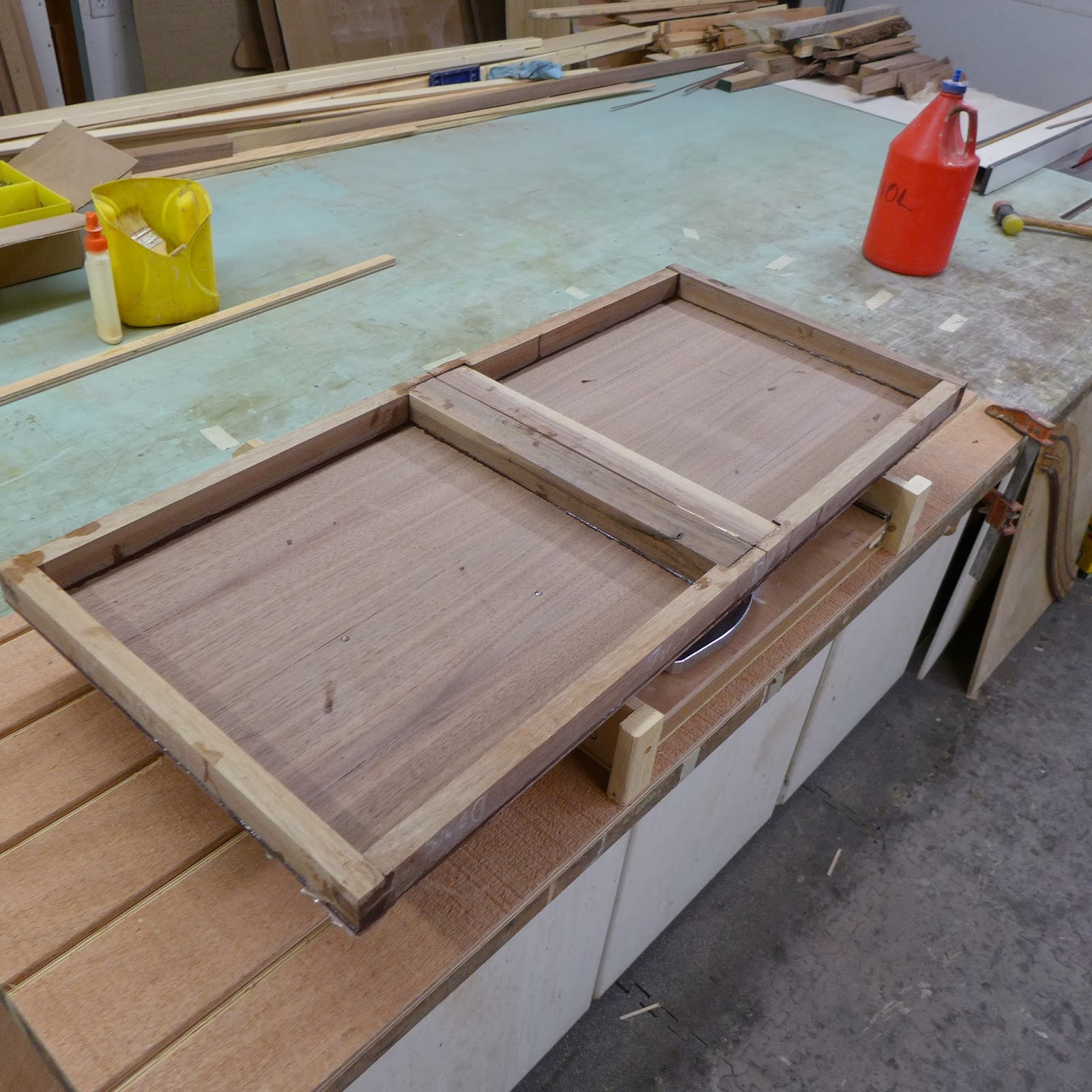
(above) The pull-out table base has a precision lazy-susan ball bearing pivot bolted to 1/2" cabinet grade mahogany plywood...The metal on the edges are the drawer are part of a set of full extension drawer guides...Those slide into the matching parts inside the curbside cabinet, next to the seat...

P1040656.JPG

(above) The walnut top (upside down) has a solid walnut edging epoxied to the top...Box joints ate the cornets...The table will fold in the middle with Soss 216 hinges, the reason the wood in the middle is that size...

P1040657.JPG

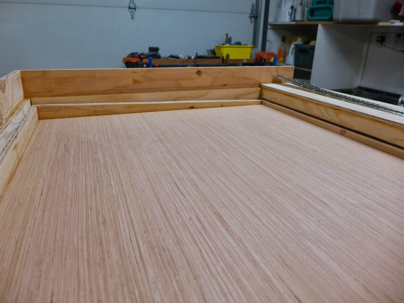
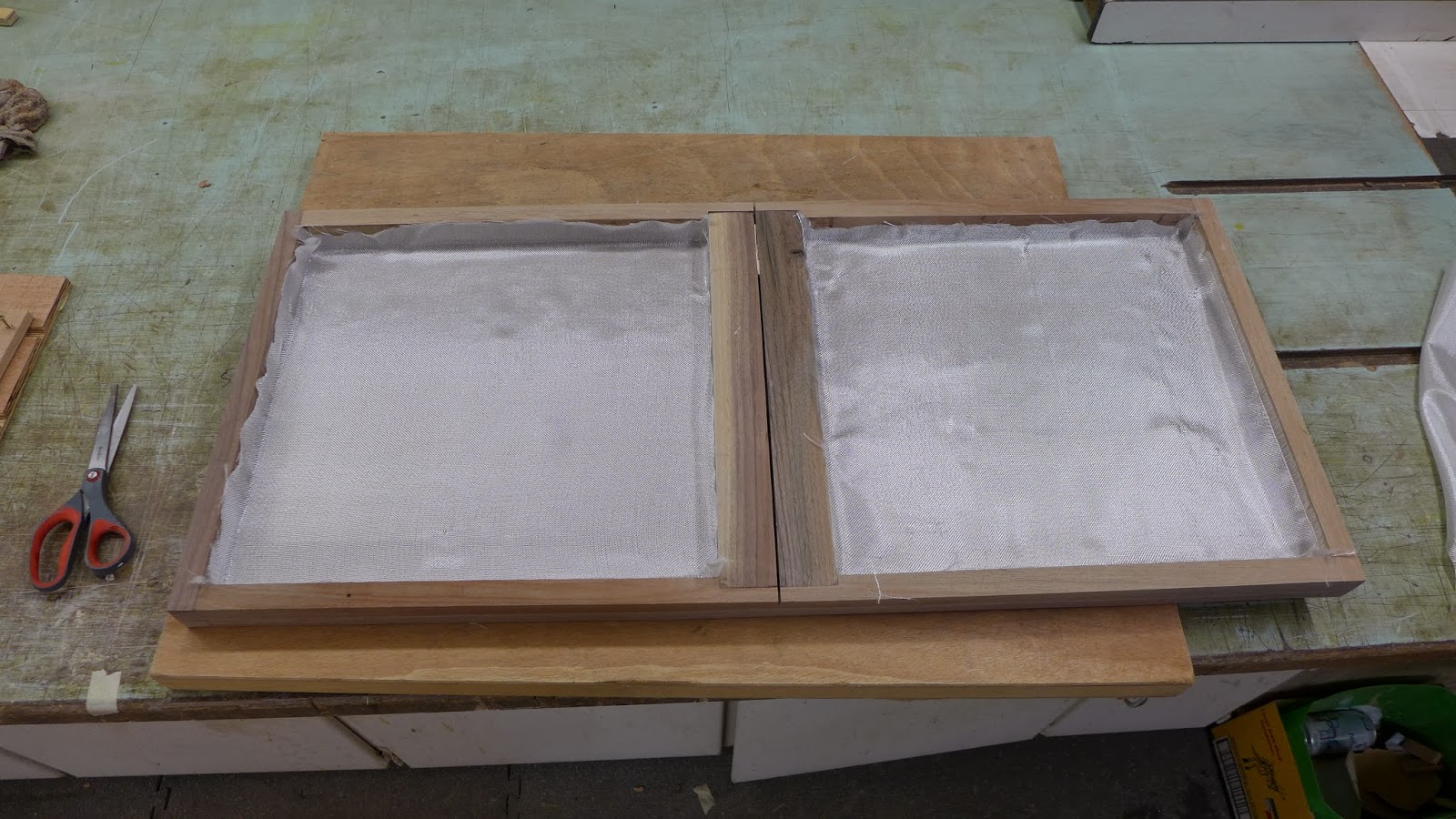
(above) Since the table-top is so thin, it gets fiberglassed on the inside...

P1040659.JPG

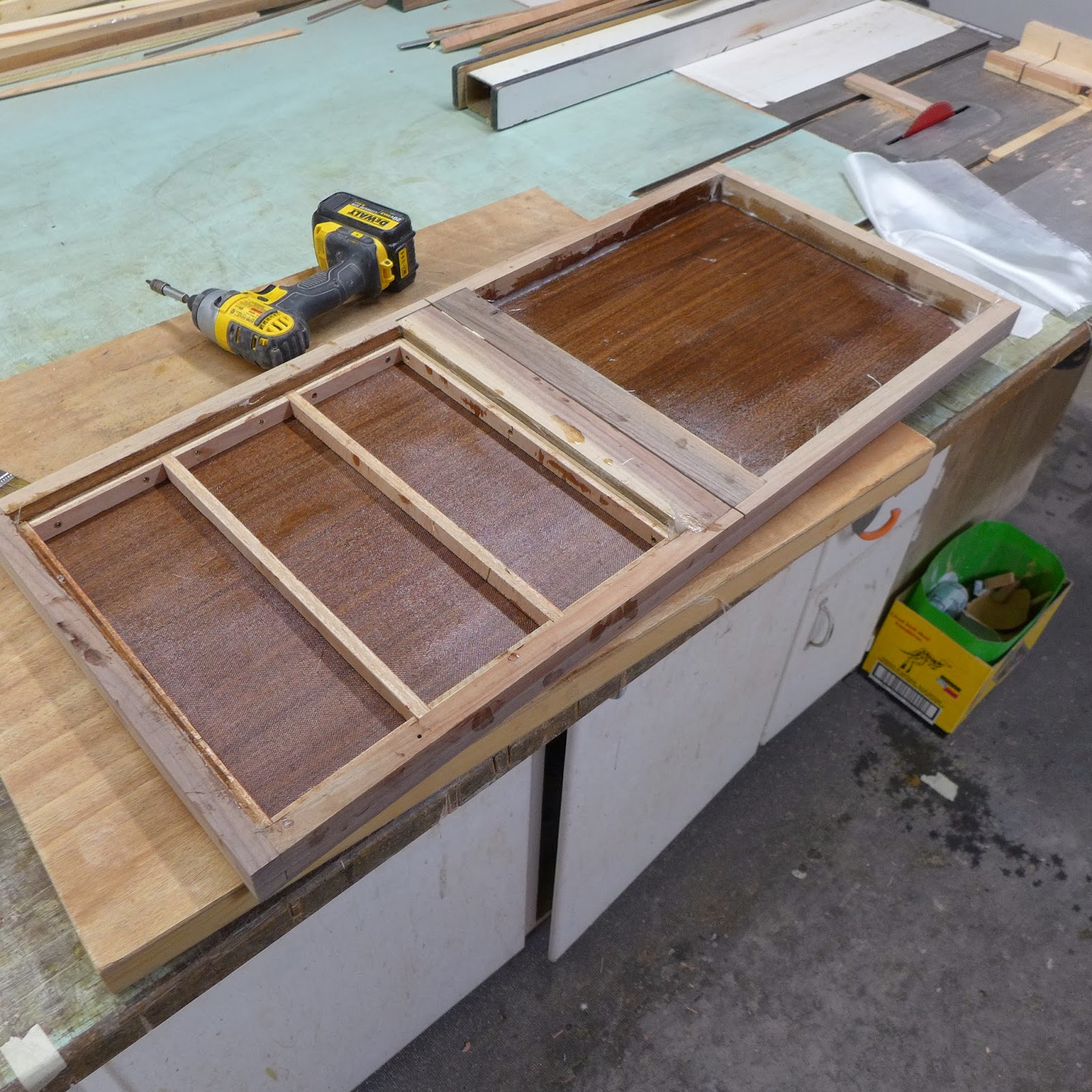
(above) While the epoxy was still wet, filler and stiffening plywood strips were screwed in place...The spacers are for the 1/2" plywood lazy susan mounting ply to be flush with the table-top bottom (not shown here)...The mounting ply on both lazy-susan surfaces are fitted with T-nuts for strength...

P1040660.JPG

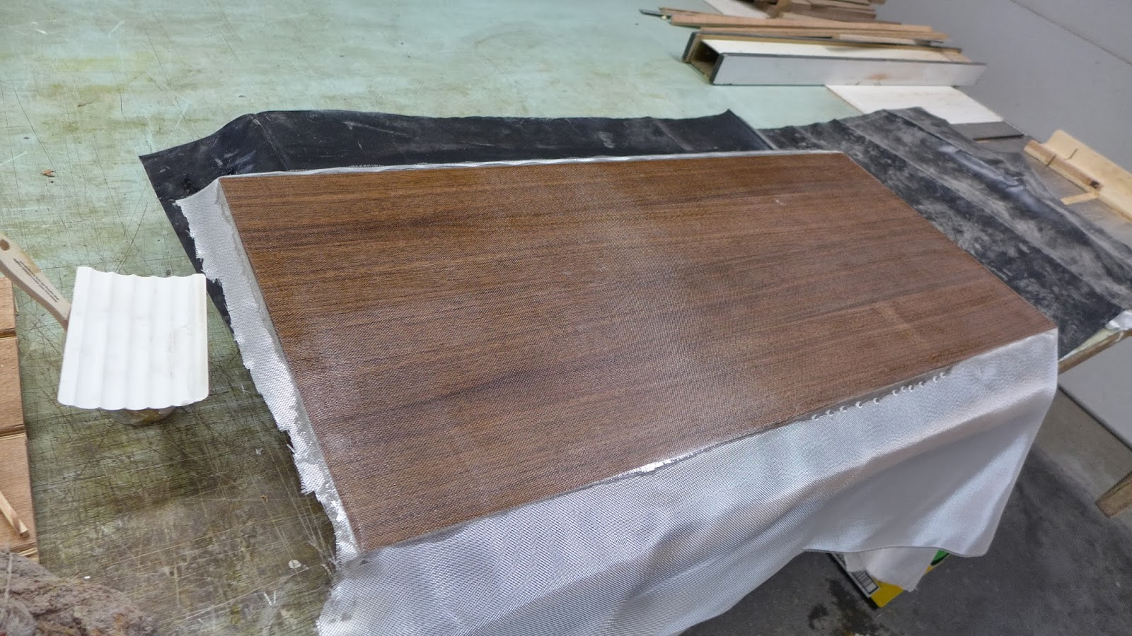
(above) Next, the table-top was flipped, sanded to 120 grit, then fiberglassed with epoxy resin...Filler coats and sanding will follow...
 

Jb1rd

Explorer
Damnnnnnnnn son!!!!! Your builds have progressed in spectacular fashion, thank you for keeping craftsmanship, creativity and a bit of DIY can do alive, truly inspiring! :Wow1:
 

Forum statistics

Threads
185,891
Messages
2,879,508
Members
225,497
Latest member
WonaWarrior
Top