dwh
Tail-End Charlie
I'm more interested in the relevance of the bulk charge etc. and how the voltage and amperage rates interact with the battery. You seem to know a bit about it so let me know what you think. I'm interested in how this might compare to what my alternator is doing to the Optima but not the DieHard.
I'm not sure exactly what your question is...
Bulk Stage: Take the battery up to a certain "surface charge" voltage to get it recharged to 80% or so fairly quickly. Most AGM and flooded specify 14.4v for this, but some chargers will go higher. As previously mentioned, the Iota with IQ/4 module goes all the way up to 14.8v. Without the IQ/4 module, the Iota has a dongle to set bulk voltage to either 14.4v (dongle unplugged) or 14.6v (dongle plugged in).
Absorb Stage: Drop the voltage to a lower value and hold it there for some hours to get that last bit into the battery to reach full charge. The usual scheme is to hold at 14.2v until the amperage flow drops below 2a or so, then switch to float.
Float Stage: Drop the voltage to an even lower value to hold the battery at full charge without holding it at overcharge voltage. Generally 13.2v-13.6v.
That's 3-stage. 2-stage chargers omit the absorb stage and drop straight from bulk to float. The Iota without IQ/4 is a 2-stage charger. The bigger Battery MINDers are 3-stage, but that little one you linked to is a 2-stage.
Then there is:
Constant Voltage: Set the charger to a specific voltage and let the battery creep up till it gets there. 99% of all automotive "bench top" chargers are Constant Voltage. The amount of amps that flow is limited either by the resistance of the battery or the max output of the charger. The resistance of the battery is highest at both ends of the scale - when it's either dead or fully charged.
Constant Current: Keep cranking up the supply voltage until a specified amount of current - such as 15a or 25a or whatever - is flowing.
Current Limited: Put a cap on the amount of current allowed to flow - again, such as 15a or 25a or whatever. All battery chargers, either constant voltage or constant current are also current limited.
Alternator / Voltage Regulator setups are basically constant voltage.
The voltage regulator controls a sort of "electrical clutch" in the alternator - the "field current" or strength of the magnetic field of the rotor.
When the voltage on the battery side of the regulator hits (usually around) 13.5v, the regulator "engages the electrical clutch" by applying power to the rotor's field coils and the alternator makes power. When the voltage on the battery side hits (usually around) 14.5v, the regulator cuts power to the rotor's field coils and "disengages the electrical clutch" and the alternator "freewheels".
With constant voltage type charging systems, you set the voltage and let the amps fall where they may. So a million amp alternator might only be producing 5a if the battery is at the regulator's set point voltage and there are only 5a of loads drawing down the bus voltage.
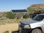
So what happens with two batteries in a truck connected together by say a solenoid?
The voltage regulator will switch on the field coils in the rotor and the alternator will make power and the batteries will absorb however many amps can flow through them. Once the two batteries reach a "surface charge" of 14.5v, then the voltage regulator will switch off the rotor and the alternator does nothing.
Then the "bus voltage" (the batteries and the rest of the 12v system in the vehicle) will drop below 13.5v if there is any load - such as a radio and some headlights. When it gets down to 13.5v the voltage regulator switches the alternator back on again. This will happen pretty quick if the batteries were only at a high surface charge and not really fully charged.
Rinse and repeat and eventually both batteries will end up pretty well fully charged. If one battery - for instance the secondary or "house" battery - is deeply drained, then it can take anywhere from 8 hours *of driving* up to 24 or even 36 hours *of driving* to get it charged up fully. (I.e., fully absorbed as opposed to just pumped up to a shallow surface charge.)
Since AGMs and flooded batteries take basically the same charge voltages, they will be fine when connected in parallel to a constant voltage system such as almost any bench-top charger or a vehicle charging system.
They'll also be fine connected together to a 2-stage charger.
Same with different size batteries. Same with different age batteries.
However...if you hook up two different size batteries to a 3-stage charger - the smaller battery will usually be way overcharged by the time the larger battery has finished absorbing - so that's a bad idea.
Also a bad idea to hook a newer battery and an older battery to a 3-stage (even if they are the same type/model of battery) since the older battery will have a lower capacity than the new one and will end up overcharged.
And of course, batteries rigged either in series or rigged in a full-time parallel bank (instead of just connected when charging such as a vehicle solenoid setup) should always be identical make/model/size/age.
GELs take a lower charge voltage than AGM/flooded and there definitely ARE "GEL Specific" chargers. Morningstar solar charge controllers have a dip switch - flipped one way it's set for "AGM/flooded" and the bulk is set to 14.4v. Flipped the other way and it's set for "GEL" and the bulk is set to 14.2v. Samlex chargers usually have the same switch but the GEL setting is 14.0v instead of 14.2v.

")