2012 LR4 Overland Project - Build Journal & Blog

treckin

Member
Ok I got the Rear Differential ECU today in the mail. Luckily they included 3 if the 4 connectors, so I can at least try to order the parts online (connector housings, terminals, crimp tools).

I haven’t had a chance to correlate all the wires to the diagrams I posted, I’ll get to that and then post an update.

The connectors are tycho part numbers. The 2.5mm^2 wires are the diff motor supply/return.

The ECU housing has the terminal numbers stamped on the male connector housings, so if I can’t source the housings and contacts I can at least solder, extend, and pot the unit and install Deutsch or similar parts.

Photos:
 

Attachments

  • 18F63AC4-2433-4B12-9DE6-72A98FBDC7B1.jpeg
    18F63AC4-2433-4B12-9DE6-72A98FBDC7B1.jpeg
    708.7 KB · Views: 56
  • 70BCCBC0-55B6-4DB8-9854-73ACF4715561.jpeg
    70BCCBC0-55B6-4DB8-9854-73ACF4715561.jpeg
    766.7 KB · Views: 55
  • 82D21D29-6B82-462D-8352-0C59CE4CE175.jpeg
    82D21D29-6B82-462D-8352-0C59CE4CE175.jpeg
    663.9 KB · Views: 53
  • D35C819F-BD2C-4063-8FCC-0AC0A8CDFD44.jpeg
    D35C819F-BD2C-4063-8FCC-0AC0A8CDFD44.jpeg
    650 KB · Views: 54
  • C1D1F0E8-BFA6-4C74-9D68-AE405C401908.jpeg
    C1D1F0E8-BFA6-4C74-9D68-AE405C401908.jpeg
    786.7 KB · Views: 51
  • 48E825BC-6985-4B4F-8FB7-5F189824C3B0.jpeg
    48E825BC-6985-4B4F-8FB7-5F189824C3B0.jpeg
    695.3 KB · Views: 55
  • 54312B78-10FE-4EB0-AA04-E7E2C2D39DBA.jpeg
    54312B78-10FE-4EB0-AA04-E7E2C2D39DBA.jpeg
    1.4 MB · Views: 54
  • 395FEE5A-2329-42D8-B653-FAF977C3E06B.jpeg
    395FEE5A-2329-42D8-B653-FAF977C3E06B.jpeg
    1.2 MB · Views: 50
  • CB0E5F22-05EA-49C6-A9DC-9DCBEC0B9DFD.jpeg
    CB0E5F22-05EA-49C6-A9DC-9DCBEC0B9DFD.jpeg
    1.5 MB · Views: 56
  • CB87DE09-9E82-455F-B4F1-B3C3DAB69DCF.jpeg
    CB87DE09-9E82-455F-B4F1-B3C3DAB69DCF.jpeg
    1.6 MB · Views: 55

treckin

Member
Ok good news is the pinout lined up.

Purple connector, Land Rover # C2162S (Vehicle HS-CAN):
  • Pin 5 is Yellow wire, brown stripe, .5mm^2, Vehicle HS-CAN (high/low are unknown, typo in wiring diagram. Simple voltmeter reading will confirm, maybe I’ll post a scope shot to show people how to check)

  • Pin 2 is Yellow wire, black stripe, .5mm^2, Vehicle HS-CAN (see note above on H/L)
Yellow Connector, Land Rover # C2163S (power, ignition signal):

  • Pin 3, black wire, 2.5mm^2, is Chassis Ground

  • Pin 6, black wire, 2.5mm^2, is Chassis Ground

  • Pin 7, Purple wire with blue stripe, 2.5mm^2, runs to vbatt via fuse Link 13e (I’ll have to find this later), 40 amps, splits from 4.0mm^2 wire from engine fuse box at Land Rover junction number SJS42S, to two 2.5mm^2 feeds to ECU, pins 7 and 8. Connector number at engine junction box/fuse is C0570L-115. Chassis harness junction, 4.0mm^2 to 4.0mm^2 is at connector C2242L-13.

  • Pin 8 see above

  • Pin 4 is ignition signal, to boot up the module. It is a red wire, 1mm^2 diameter. It runs to junction SJ971, where it shrinks in diameter to .75mm^2 (to counter LV voltage drop over distance/ohm feet). From there it connects to c1167L-21, and finally at the central junction box (cabin?) fuse 22P, 5 amps, cia connector c0582-40.

Black connector, C2164S (differential signals and controls):

  • Pin 18 is the differential motor solenoid positive feed, a red wire of 1mm^2 diameter, running to connector c2168 on the diff, pin 2.

  • Pin 17 is the differential motor solenoid negative return, a green wire of 1mm^2 diameter, running to c2168, pin 9.

  • Pins 13 and 16 are the LVDS signal from the diff motor temperature sensor. They’re UTP (unshielded twisted pair) .5mm^2 diameter. Pin 13 is blue wire, pin 16 is white. They also run to C2168, blue goes to pin 7, white to pin 8.

  • Pin 3 is the diff motor battery positive feed, it is a red wire, 2.5mm^2 diameter. It runs to C2168 pin 1.

  • Pin 12 is the diff motor negative return, it’s a blue wire, 2.5mm^2 diameter, and runs to C2168 on the diff, pin 10.

  • Pin 1 is the Hall effect motor position sensor voltage supply, a green wire with .5mm^2 diameter running to C2168 pin 3, on the diff.

  • Pin 10 is the motor position sensor ground path, a brown wire of .5mm^2 diameter going to pin 4 on C2168 on the diff.

  • Pin 4 is shift lock signal, I’m assuming the positive signal that the diff is locked, possibly variable. It’s a silver wire, .5mm^2, going to C2168 pin 5 on the diff.

  • Pin 7 is an orange wire, being labeled “hall signal B” which I assume is the hall raw sensor input for rationality/health checking, with a .5mm^2 diameter, running to pin 6 on C2168 on the diff.

  • Finally pins 8 and 11 are a red and yellow respectively UTP/LVDS pair of .5mm^2 diameter wire. Pin 8 goes to a separate connector, C0269, on the diff oil temp sensor, pin 1, while pin 11 goes to C0269, pin 2.
And that’s it!

As soon as I get the diff I’ll do a tear down and post those pics here too.

Cheers mates!
 
Last edited:

ar4me

Adventurer
Nice work!

BTW, checked this morning on fwy, and at 70 mph, my speedometer shows 3 mph too low as well, even with 406mm setting :( So either LR does not accommodate that large a deviation from stock in their software, or the iidtool is still buggy...
 

treckin

Member
Nice work!

BTW, checked this morning on fwy, and at 70 mph, my speedometer shows 3 mph too low as well, even with 406mm setting :( So either LR does not accommodate that large a deviation from stock in their software, or the iidtool is still buggy...

Thanks! This is good to know - I am beginning to suspect our initial hypothesis to be correct, the changes do affect the indicated speed, however there’s a limit to the calibration.

Maybe we could both raise the issue with GAP (I do understand you said their service is pretty non-existent). I’ll need their a la carte service for the locking differential retrofit as well, hopefully that’s painless.

Differential arrives tomorrow, fingers crossed on that one!
 

ar4me

Adventurer
Patrick at support used to always reply promptly and be super helpful. He gave me access to beta releases of firmware with the understanding that it might not be fully stable. As an engineer I was fine being a bit of a guinea pig and then have access to some advanced/early new features, etc. Recently, I haven't gotten any replies when I email him - I wonder if he left GAP Diagnostics...? My last email from him was April 5.
 

RR876

Member
As previously suggested, you may be coming up against a hard limit of tyre size programmed into the engine management system.

Back in the day when I used to calibrate engines for Ford, there were parameters for the min and max allowed tyre size allowable. Depending on the calibrator, this could be set to a range of sizes for which the emissions performance was validated or it could be set for a very broad range of options. There was no set rule at the time I was there.

The point is, there may be not a lot you can do about it.


Sent from my iPhone using Tapatalk
 

treckin

Member
As previously suggested, you may be coming up against a hard limit of tyre size programmed into the engine management system.

Back in the day when I used to calibrate engines for Ford, there were parameters for the min and max allowed tyre size allowable. Depending on the calibrator, this could be set to a range of sizes for which the emissions performance was validated or it could be set for a very broad range of options. There was no set rule at the time I was there.

The point is, there may be not a lot you can do about it.


Sent from my iPhone using Tapatalk

Thanks for the input! I wonder if the other options can be manipulated a bit as well... also, 3pmh slow at 70 might be about right for a factory offset. Does anyone know what the factory Speedo offset is?
 

BSC_100

New member
Sure about that? I tried on my LR4, and it makes zero difference to the speedometer reading on my car.

@ar4me I recently went through the same thing trying to use the IIDTool to adjust the CCF in my 2013 RRS to account for oversized 285/50R20 tires. Changing the Tyre Rolling Radius setting had no effect on my speedo or odometer values (which were 10% below actual due to the tires). Nor did any of the other settings. Finally, I tried changing the "Tire Size MSB - IPC" setting. I lowered that setting to 28. This made by odometer dead on and my speedo within 1 mph. I thought the Tyre Rolling Radius setting worked for LR4's, but since it's not working for you, you may want to try Tire Size MSB. I have no idea what this setting is but lowering it raised my speedo reading (and vice versa).

@treckin That's interesting what you said about the CCF changes not working possibly because the value is stored as a 256 bit number. "Tire Size MSB" = most significant bit?

I'm also interested in the effect beyond the speedo reading. That is actually the more important issue for me since, as you say, the ABS wheel speed sensors feed their data to the traction control and a number of other systems essential for off-road performance. Let me know if you figure anything else out about the system interdependence and whether getting the right speedo value means the other systems are corrected as well.
 

ar4me

Adventurer
@ar4me I recently went through the same thing trying to use the IIDTool to adjust the CCF in my 2013 RRS to account for oversized 285/50R20 tires. Changing the Tyre Rolling Radius setting had no effect on my speedo or odometer values (which were 10% below actual due to the tires). Nor did any of the other settings. Finally, I tried changing the "Tire Size MSB - IPC" setting. I lowered that setting to 28. This made by odometer dead on and my speedo within 1 mph. I thought the Tyre Rolling Radius setting worked for LR4's, but since it's not working for you, you may want to try Tire Size MSB. I have no idea what this setting is but lowering it raised my speedo reading (and vice versa).
Interesting you should suggest to try change that parameter... I have been communicating with Patrick (at GAP) today, and he suggested trying that parameter. My original value is 31, and I would have thought I would need to increase it to the actual tire size used - mine are now 32. But, it seems you lowered yours...?
 

BSC_100

New member
Interesting you should suggest to try change that parameter... I have been communicating with Patrick (at GAP) today, and he suggested trying that parameter. My original value is 31, and I would have thought I would need to increase it to the actual tire size used - mine are now 32. But, it seems you lowered yours...?
Yeah I worked through this with Patrick and kept him updated about what setting worked. I also assumed Tire Size MSB - IPC value referred to tire diameter because it was initially set to 31, and tire diameter seemed to be the only relevant number in that area. But that appears to be just a coincidence. Per Patrick it means Most Significant Byte. And for whatever reason lowering it raised the displayed speed reading.
 

ar4me

Adventurer
Yeah I worked through this with Patrick and kept him updated about what setting worked. I also assumed Tire Size MSB - IPC value referred to tire diameter because it was initially set to 31, and tire diameter seemed to be the only relevant number in that area. But that appears to be just a coincidence. Per Patrick it means Most Significant Byte. And for whatever reason lowering it raised the displayed speed reading.
Thanks! Will give it a try tonight.
 

treckin

Member
Thanks! Will give it a try tonight.

Post the results!

I’ll poke around at work - I know we have a couple people from JLR who worked on controls FW, I’ll see what they know about the TRS/ABS/DSC/HDC and tire radius.

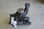
On a sad note, I got the differential in the mail today and it’s of course the non-locking unit. I have a message out to the seller.

Attached is what was sent, and here’s a pick of the Centurion Differentials unt (still trying to understand what the difference between the 2007-2009 locking rear is, if any):
789D6058-0538-436C-B7B3-A70C559566B0.jpeg
 

Attachments

  • F2D7A039-AD9F-48AD-9295-216EE3CE3A74.jpeg
    F2D7A039-AD9F-48AD-9295-216EE3CE3A74.jpeg
    2.9 MB · Views: 63
  • 12E1CF60-3B02-43DA-A822-CAE647A88260.jpeg
    12E1CF60-3B02-43DA-A822-CAE647A88260.jpeg
    2.4 MB · Views: 63
  • 638E1979-4ED6-497F-8A64-411A1106C7A1.jpeg
    638E1979-4ED6-497F-8A64-411A1106C7A1.jpeg
    2 MB · Views: 63
  • 4D361143-8B99-49F4-B0B3-CA5B1F5DA941.jpeg
    4D361143-8B99-49F4-B0B3-CA5B1F5DA941.jpeg
    1.5 MB · Views: 63
  • 7185AAB2-4CB7-4731-906D-08D6BE878854.jpeg
    7185AAB2-4CB7-4731-906D-08D6BE878854.jpeg
    1.9 MB · Views: 59

RR876

Member
IPC stands for Instrument Panel Cluster. That is, the parameter is probably used by the cluster module for calculating what to display. MSB will be the Most Significant Byte. The parameter may be the number of wheel rotations per unit distance or the engine to wheel speed ratio in a particular gear, so could conceivably decrease for larger tyres.

This parameter may or may not be used for the speed calculation for other systems. Vehicle speed is used by almost every module but there are many values used for different applications. The good news is that a more correct speed reading is always better than a poor one and so you can only make things better sorting this out.


Sent from my iPhone using Tapatalk
 

Forum statistics

Threads
188,562
Messages
2,906,949
Members
230,666
Latest member
Cvonruex
Top