You are using an out of date browser. It may not display this or other websites correctly.
You should upgrade or use an alternative browser.
You should upgrade or use an alternative browser.
Blender, My LX450/FZJ80 + FJ45esk + GM + Land Rover crazy concoction
- Thread starter Metcalf
- Start date
oliverlove
Adventurer
As a total novice to the modification/fabrication world, this is pretty cool to see happen. I love how well you are documenting it as you go, it makes it fun to read and I'm learning.
Metcalf
Expedition Leader
As a total novice to the modification/fabrication world, this is pretty cool to see happen. I love how well you are documenting it as you go, it makes it fun to read and I'm learning.
No problem. Thank you for watching.
Metcalf
Expedition Leader
A little how-to tech tip....
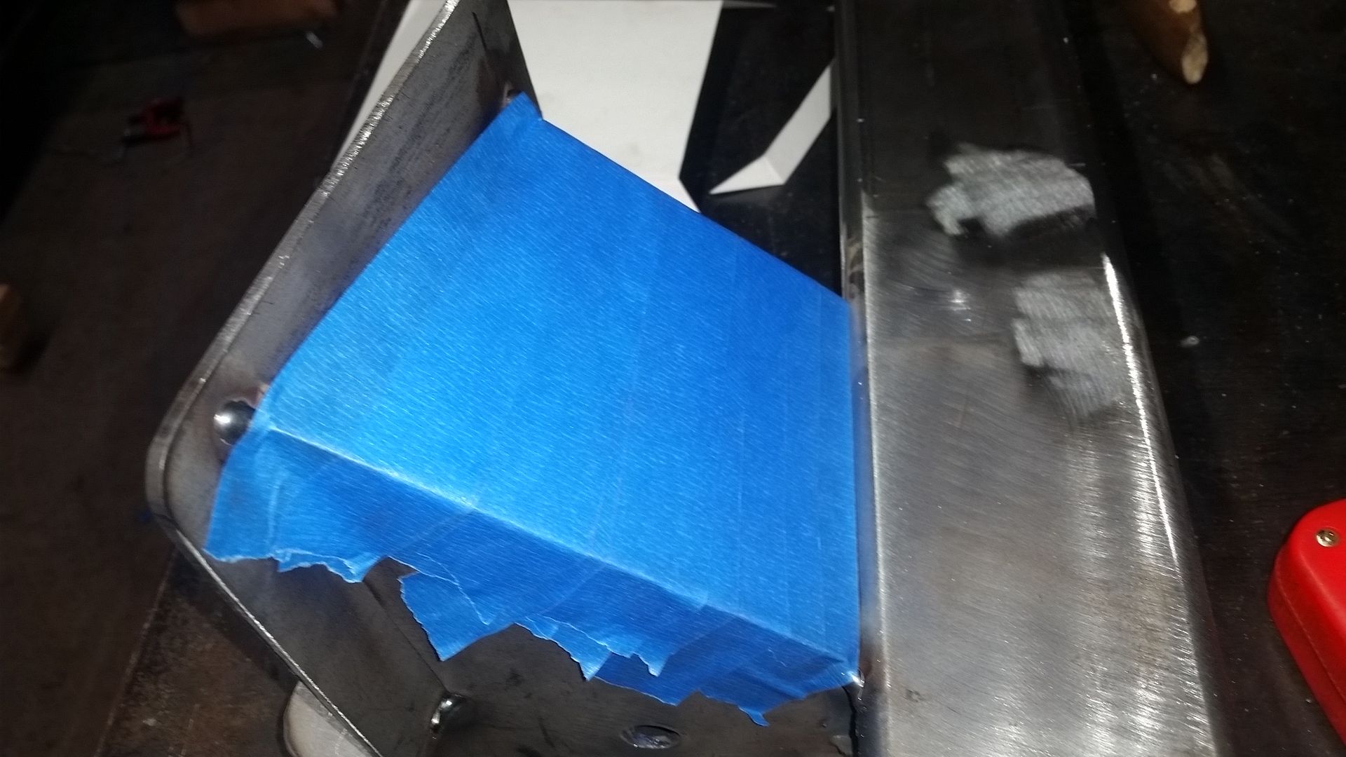
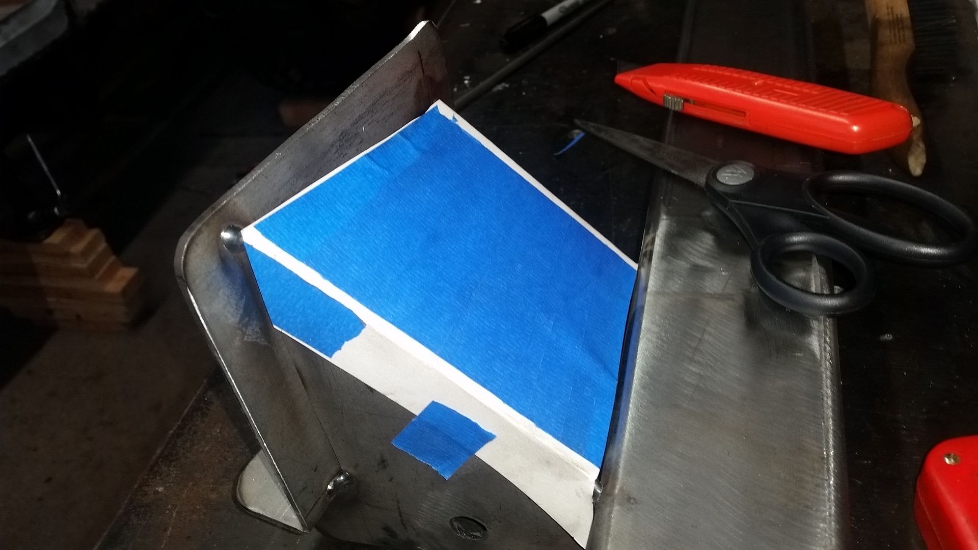
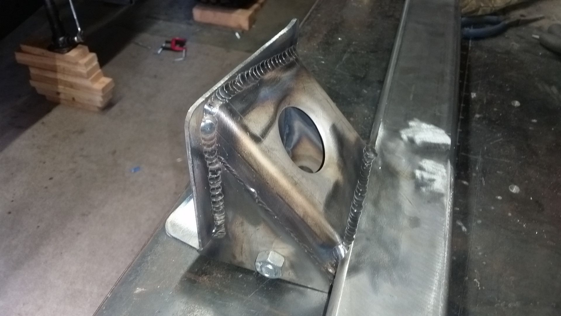
Sometimes, when working with more complex shapes, I find it handy to use an 'additive' process for making templates rather than a subtraction method. In this case. I used making tape to make a skin over the area where I needed a boxing plate. I trimmed that masking tape template out of the steel and used it as a base for the poster board template which had the flanges I needed to fabricate.
Just a helpful tip I hope.
Metcalf
Expedition Leader
Helpful indeed! Thanks for documenting stuff like that.
I don't know about all that, but thank you for watching.
Metcalf
Expedition Leader
Just a few sneak peaks because all I did was stare at things for like an hour and measure stuff....
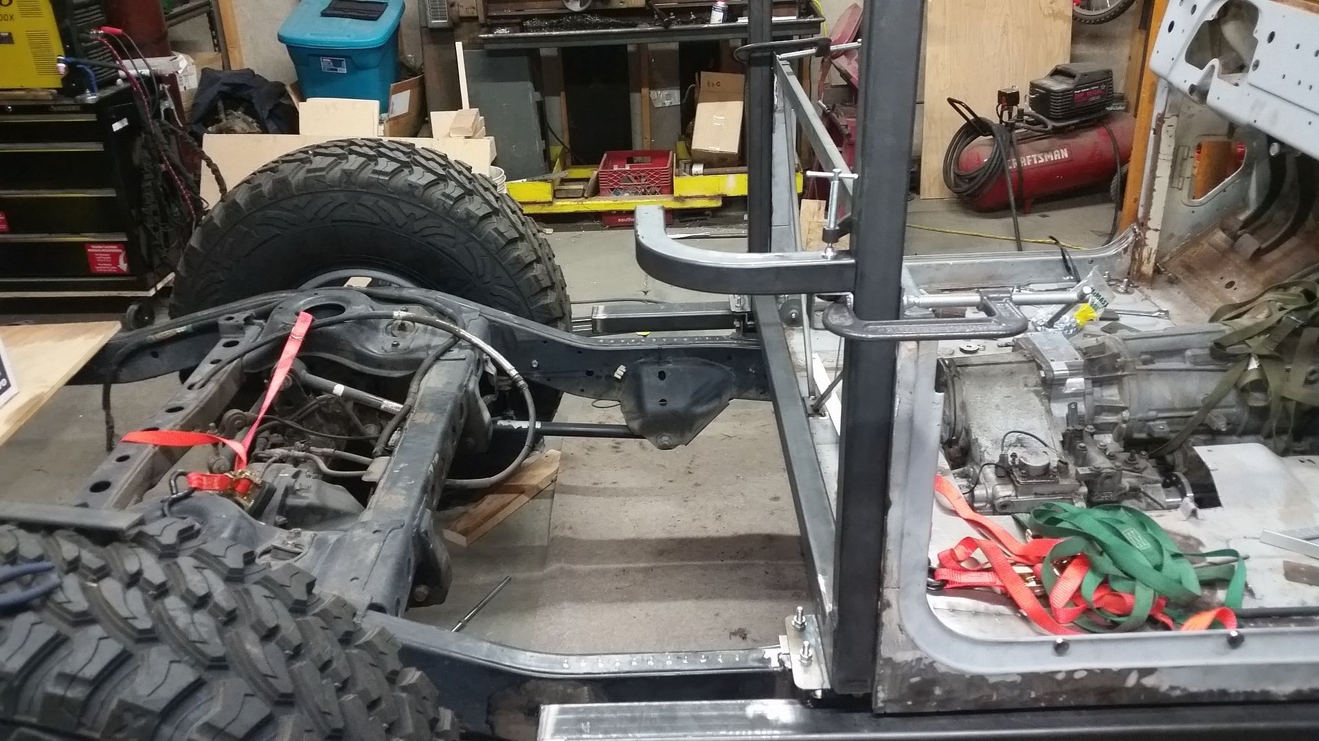
This is one of the square tube mandrel bends I will be using to form the rear of the tub. I will be using 4 total, 2 per side. One per side will be similar to this location but not exactly known yet. I will be connecting them with a straight section of matching 1.5"x.120 wall square tube with some internal sleeves at the joints. This structure will for the beltline/waistline of the rear of the tub. This tube should also be able to serve as the 3/4-point harness mount tube.
You can also get a rough idea of the total length of the tub. I believe this is about 3" longer than a stock FJ45 pickup tub. I don't know how much that matters since I have never sat in one, but it should be downright roomy compared to my flat fender!
I will be splitting the rear 'window' panel down the middle with another single C-pillar tube and it will have a 5th body mount bushing that will tie into the bed floor structure area.
The lower part of the tub will be sheetmetal. Basically a skin that wraps around the sides to the B-pillar tube with a flange at the top and bottom. It will hang on the cage basically.
I will also have to build a rear floor and spot weld the bottom seams together.
The bigger question is what to do with the cage top halo. I will write something about that later.
Metcalf
Expedition Leader
Metcalf
Expedition Leader
Lots of measuring and making stuff ( in the computer )
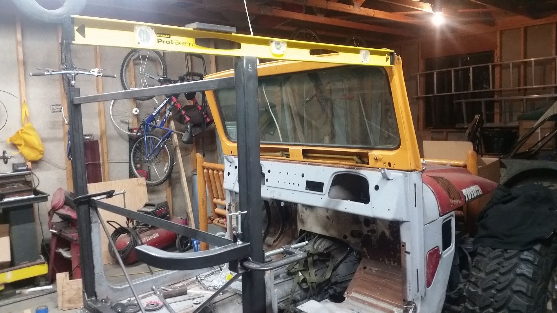
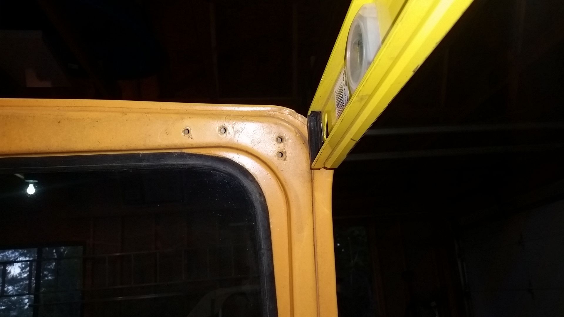
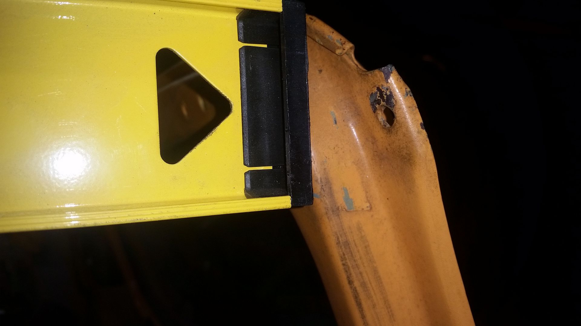
So this is basically that I am working with right now.
In the first picture you can see how setting a 'halo' on the top of the B-pillar will look. I tried to guess at the 'stock' position of the door opening in relationship to the stock windshield. Doing this from pictures is always fun!
In the 2nd picture you can see the four mounting holes on the back of the windshield frame. The two outer holes are where the stock door door surround attached. The inner two holes are for the sun visor. I am thinking that I will use all 4 holes for a mounting plate similar to how a YJ/TJ dead ends the cage structure into the back of the windshield frame. I don't really want to have to mess with the factory style windshield latches on the top of the dash. Using these holes for a mounting plate should allow me to eliminate those features. I can bolt the visor through the bracket. I don't really like folding down the windshield so if that takes a little time that is fine.
In the 3rd picture you can see this odd outboard mounting bolt flange. This is basically in the front upper corner of the door. The top of that feature, where it is flat, is where the roof panel flange is located. Once of the main features I wanted with this vehicle was a modular hard top system. In order to make that practical, I needed a framework that I will bolt those panels into. Since the cabin area is smaller on this truck, I figure that combining the need for top panel framework into a 'roll cage' type structure will save work in the end.
This is basically the direction I am going....
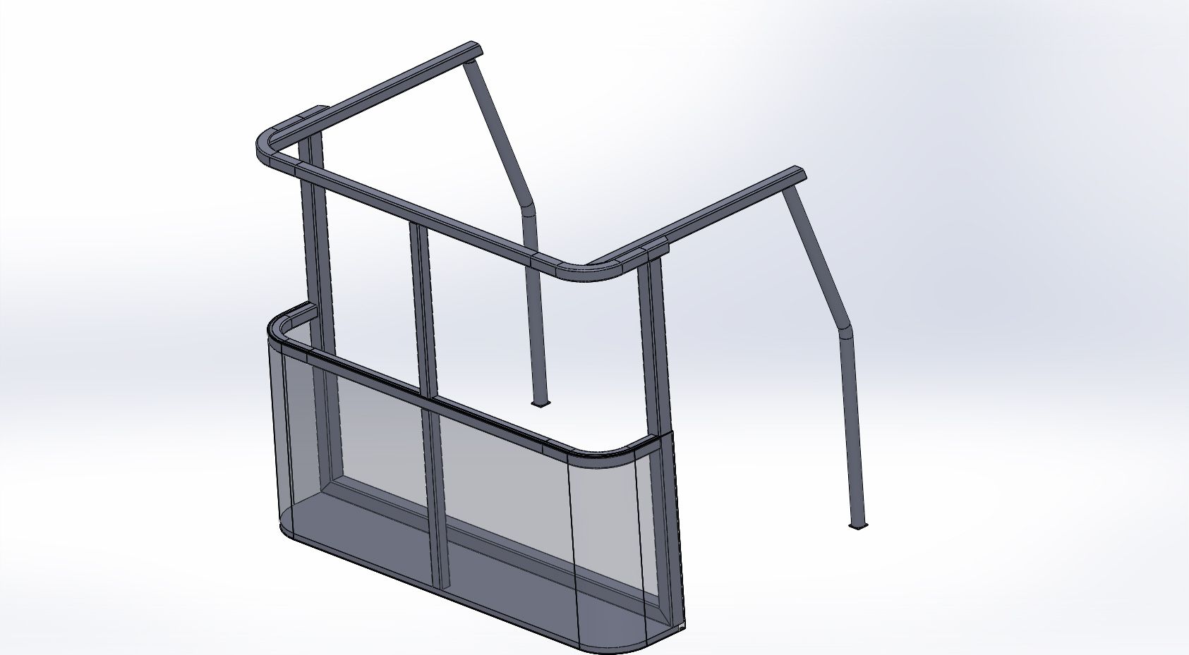
This isn't a complete rendering, but it gives you the idea. I have already built the B-pillar at the rear of the door. That is the larger 2x2 square tube structure which has a full side to side spreader at floor level. You can also see the rear cabin framework along with some rough A-pillar down tubes.
What isn't shown. I will be adding a rolled/bent A-pillar spreader at the top of the windshield. The A-pillar will be welded to all the existing dash/cowl structure after I move a few things around. I will also be adding a small front to back overhead console' tube from the A-pillar to the rear of the halo. That console will be narrow but will provide some support of the middle of the future top panel, an interior light, etc. I will be adding a 5th body mount on the single c-pillar upright that will mount to some of the structure for the stepside bed I have planned. I may tie that C-pillar into the B-pillar floor spreader bar also.
I will also be building some sheetmetal upper door surrounds to provide a sealing surface for the door bulb seal along the top and upper rear. To allow the door to sit flush with the outside of the body, I had to offset the upper part of the halo to provide room. This actually come in handy because of where the A-pillar tube lands since it can only go so far outboard with the factory door sheetmetal.
There will also be some gussets that serve double duty at some of the tube joints while also providing a mounting tab for the rear window panels. My intent is to have a 'split' rear window panel where there will be a lift and right side. I will stick a window in each panel. Those panels, when I remove them to open up the cabin, will store in the lower part of the body. They won't take up a lot of space elsewhere, but should be rather protected. To make this possible. I will have to slightly raise the belt line of the tub about 2.5"
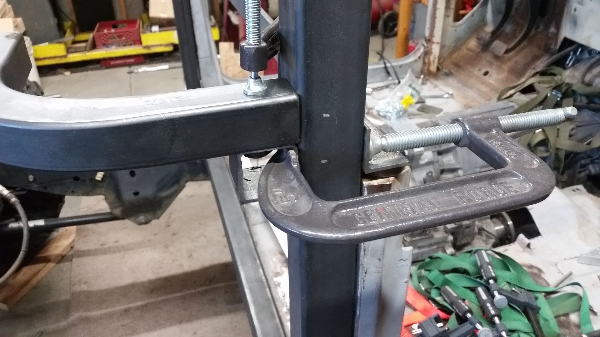
If you look close, you can see the white tick marks for the 'final' position of the belt-line tube structure. The only reference to the old height will be the seam at the top of the factory door opening. I will probably be able to eliminate that with a little work. I will also be adjusting the height of the future half doors to match that. I am going to try and make the doors basically horizontal on top vs how a typical jeep half door is done. I want to be able to have a large sliding glass upper assembly that is can be removed in nice weather.
The top panel is going to be the biggest challenge in all this I think. I want to recreate a stock looking top panel to fit this body. I will likely have to make that from scratch. I believe it will have to have about 3-3.5" of crown. I have never really made a panel like that, so that should be fun! It will also have a reverse flange around the perimeter to form the drip rail. I believe that panel will be about 40"x56".
That is all I have for now. I am off on vacation for a week. That will give me a bit more time to think over all the details I am missing.


So this is basically that I am working with right now.
In the first picture you can see how setting a 'halo' on the top of the B-pillar will look. I tried to guess at the 'stock' position of the door opening in relationship to the stock windshield. Doing this from pictures is always fun!
In the 2nd picture you can see the four mounting holes on the back of the windshield frame. The two outer holes are where the stock door door surround attached. The inner two holes are for the sun visor. I am thinking that I will use all 4 holes for a mounting plate similar to how a YJ/TJ dead ends the cage structure into the back of the windshield frame. I don't really want to have to mess with the factory style windshield latches on the top of the dash. Using these holes for a mounting plate should allow me to eliminate those features. I can bolt the visor through the bracket. I don't really like folding down the windshield so if that takes a little time that is fine.
In the 3rd picture you can see this odd outboard mounting bolt flange. This is basically in the front upper corner of the door. The top of that feature, where it is flat, is where the roof panel flange is located. Once of the main features I wanted with this vehicle was a modular hard top system. In order to make that practical, I needed a framework that I will bolt those panels into. Since the cabin area is smaller on this truck, I figure that combining the need for top panel framework into a 'roll cage' type structure will save work in the end.
This is basically the direction I am going....

This isn't a complete rendering, but it gives you the idea. I have already built the B-pillar at the rear of the door. That is the larger 2x2 square tube structure which has a full side to side spreader at floor level. You can also see the rear cabin framework along with some rough A-pillar down tubes.
What isn't shown. I will be adding a rolled/bent A-pillar spreader at the top of the windshield. The A-pillar will be welded to all the existing dash/cowl structure after I move a few things around. I will also be adding a small front to back overhead console' tube from the A-pillar to the rear of the halo. That console will be narrow but will provide some support of the middle of the future top panel, an interior light, etc. I will be adding a 5th body mount on the single c-pillar upright that will mount to some of the structure for the stepside bed I have planned. I may tie that C-pillar into the B-pillar floor spreader bar also.
I will also be building some sheetmetal upper door surrounds to provide a sealing surface for the door bulb seal along the top and upper rear. To allow the door to sit flush with the outside of the body, I had to offset the upper part of the halo to provide room. This actually come in handy because of where the A-pillar tube lands since it can only go so far outboard with the factory door sheetmetal.
There will also be some gussets that serve double duty at some of the tube joints while also providing a mounting tab for the rear window panels. My intent is to have a 'split' rear window panel where there will be a lift and right side. I will stick a window in each panel. Those panels, when I remove them to open up the cabin, will store in the lower part of the body. They won't take up a lot of space elsewhere, but should be rather protected. To make this possible. I will have to slightly raise the belt line of the tub about 2.5"

If you look close, you can see the white tick marks for the 'final' position of the belt-line tube structure. The only reference to the old height will be the seam at the top of the factory door opening. I will probably be able to eliminate that with a little work. I will also be adjusting the height of the future half doors to match that. I am going to try and make the doors basically horizontal on top vs how a typical jeep half door is done. I want to be able to have a large sliding glass upper assembly that is can be removed in nice weather.
The top panel is going to be the biggest challenge in all this I think. I want to recreate a stock looking top panel to fit this body. I will likely have to make that from scratch. I believe it will have to have about 3-3.5" of crown. I have never really made a panel like that, so that should be fun! It will also have a reverse flange around the perimeter to form the drip rail. I believe that panel will be about 40"x56".
That is all I have for now. I am off on vacation for a week. That will give me a bit more time to think over all the details I am missing.
justcuz
Explorer
Whew! Lots of work on the body and related support structure. Looks like it will be very strong.
Could you find a stock FJ 40 roof, pie cut it and horizontally section it to match the the narrowed/lengthened cab?
May be easier than creating the crown of the roof structure.
Could you find a stock FJ 40 roof, pie cut it and horizontally section it to match the the narrowed/lengthened cab?
May be easier than creating the crown of the roof structure.
Last edited:
Metcalf
Expedition Leader
Whew! Lots of work on the body and related support structure. Looks like it will be very strong.
Could you find a stock FJ 40 roof, pie cut it and horizontally section it to match the the narrowed/lengthened cab?
May be easier than creating the crown of the roof structure.
Maybe, since I am stretching the cabin area from 'stock' FJ45 length a little bit, things become a little more complicated.
If I did start with a stock roof panel I would have to cut it into a lot of pieces and hope it all came back together somehow. Once you pie cut something the rear lines change, changing lengths makes you have to add/subtract crowned material, then you have to blend it all together. At some point, starting from scratch will be easier....I am not 100% sure where that point is.
Making the top panel is a personal challenge to push my skills. I really want to make that panel out of slightly thicker aluminum material for some added structure in case the vehicle where to roll in soft material. I also want to try to make it in one piece to eliminate having to finish a bunch of seams out for paint. Making the female buck will be the hardest part. Once I have the buck, I think forming the material will actually be pretty easy with a 'flow florming' process. Making an accurate, and symmetric, female buck with about 3" of depth will be a challenge. I am tossing around a few ideas on how to make that, it is still a ways off so I have time to ponder. I really don't even have to do that till after the vehicle is running for the most part. The top will be an add-on 'modular' feature to the vehicle.
What an incredible build! I never find myself having the patience to bother with SolidWorks when I'm in the middle of a fabrication project. Those of you whom I consider high end fabricators (You, MGMetalworks, etc) take the time to model everything up and then directly apply those models to your fabrication. I guess it comes down to time for me, and the additional effort you guys are putting in makes a huge difference in assembly quality.
Subscribed!
SG
Subscribed!
SG
Metcalf
Expedition Leader
What an incredible build! I never find myself having the patience to bother with SolidWorks when I'm in the middle of a fabrication project. Those of you whom I consider high end fabricators (You, MGMetalworks, etc) take the time to model everything up and then directly apply those models to your fabrication. I guess it comes down to time for me, and the additional effort you guys are putting in makes a huge difference in assembly quality.
Subscribed!
SG
Thank you very much for the compliments. I keep trying to push my skills as much as I can while working out of my garage
I use Solidworks every day at my 9 to 5 so I am pretty fast with it. Honestly on this build I have not been using it as much....some...but not the entire car. I do have some projects that I would like to do where just about the entire vehicle has been modeled 100% to scale in Solidworks. This would be an example of that....
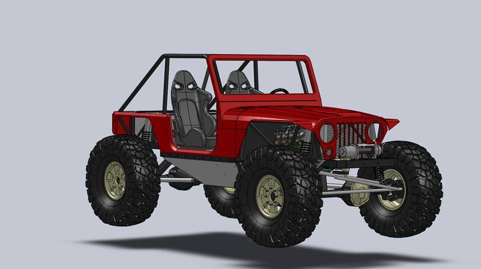
You don't want to know how many hours I have in that project JUST in Solidworks already!
I have a few more chassis that I have been working on intermittently that will require even more work since they pretty much use no existing body panels....
Thanks again.
Similar threads
- Replies
- 6
- Views
- 668
- Replies
- 10
- Views
- 2K
- Replies
- 2
- Views
- 3K

