Blender, My LX450/FZJ80 + FJ45esk + GM + Land Rover crazy concoction

Metcalf

Expedition Leader
Just duplicating the A-pillar rocker outrigger on the drivers side...


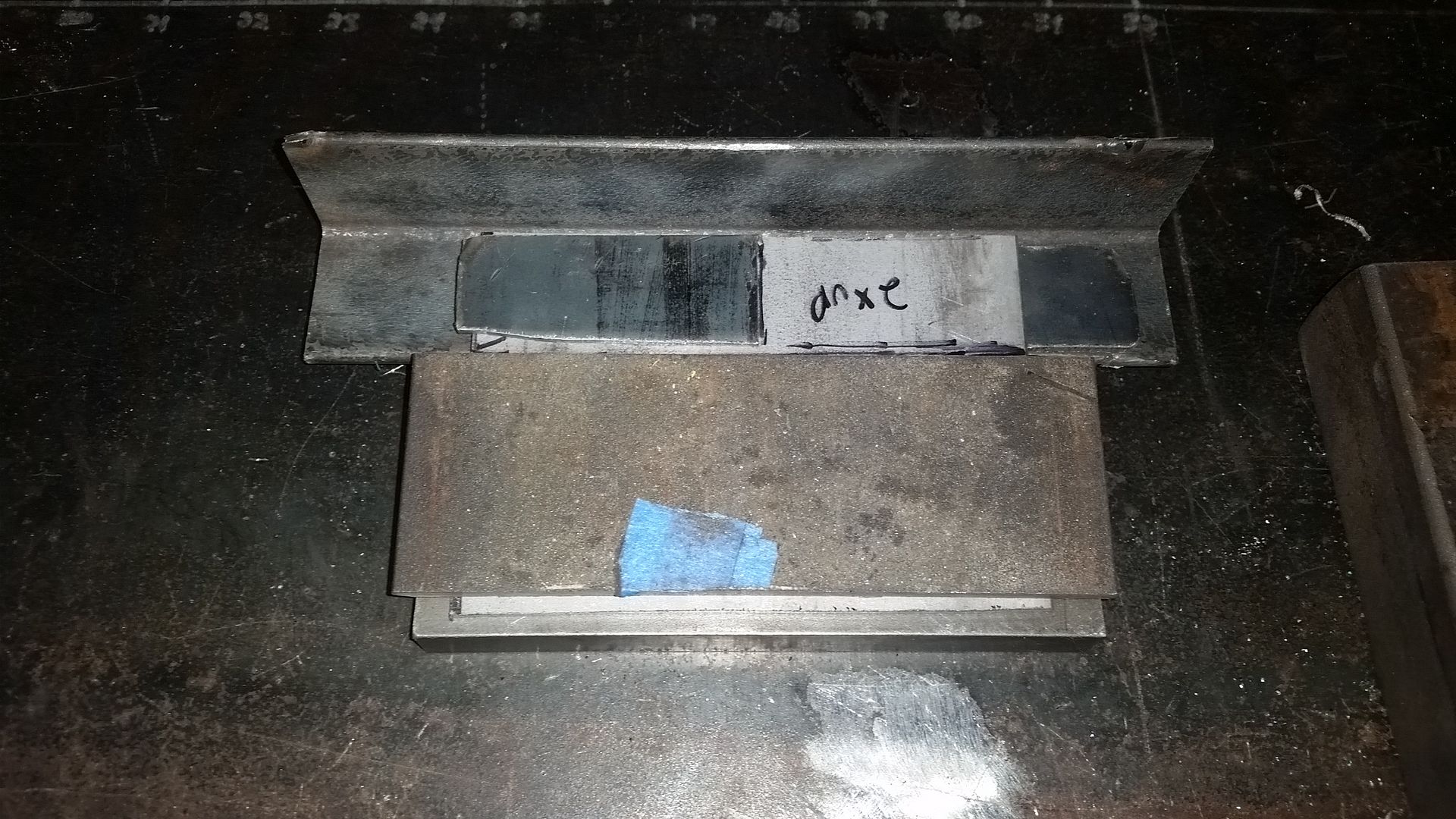
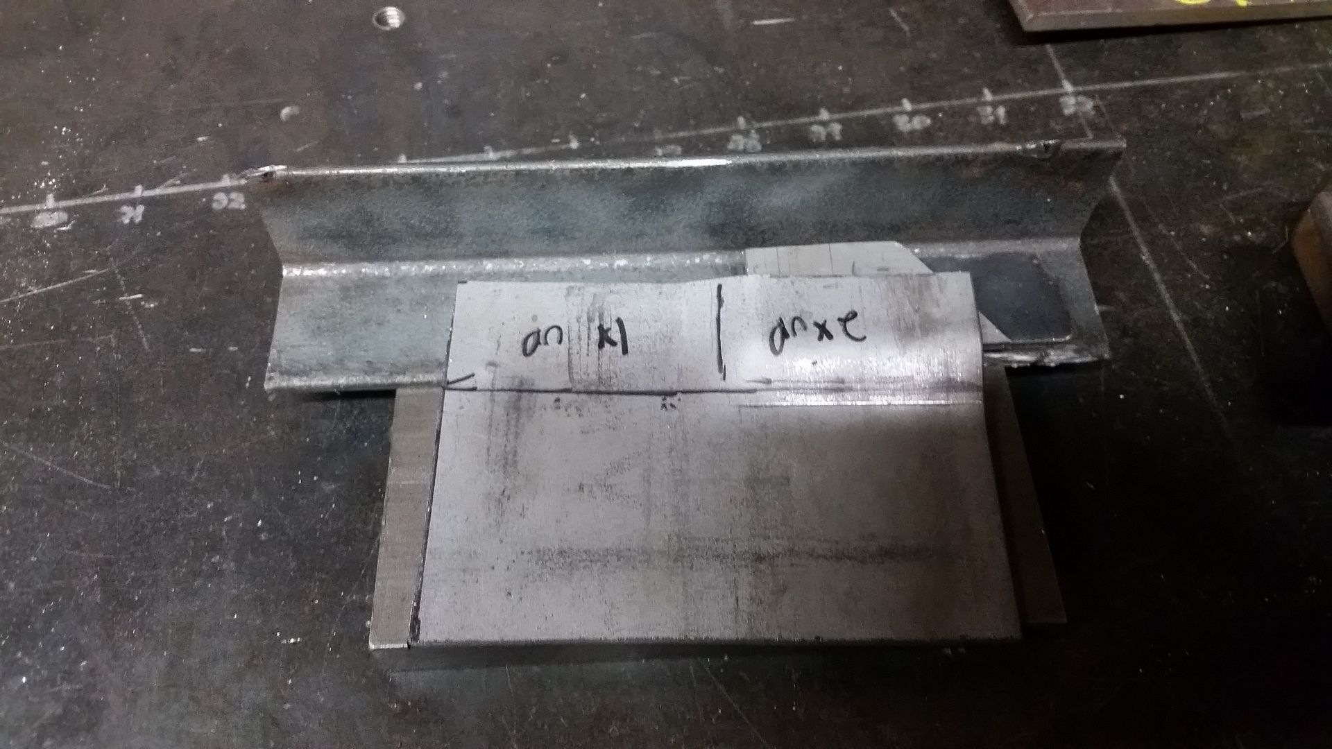
This is how I pressed the part that needed to form around the multiple steps on the rear of the mount. There are 3 levels in this. I was able to assemble a simple one off press brake die using scraps I had laying around. By stacking up different levels of material, then stacking a thick plate over everything, and squishing it in the 20 ton press, I was able to make the part I needed without investing a lot of time in a one off tool.

I have no idea how I come up with this stuff sometimes. I am REALLY surprised that worked as well as it did both times.


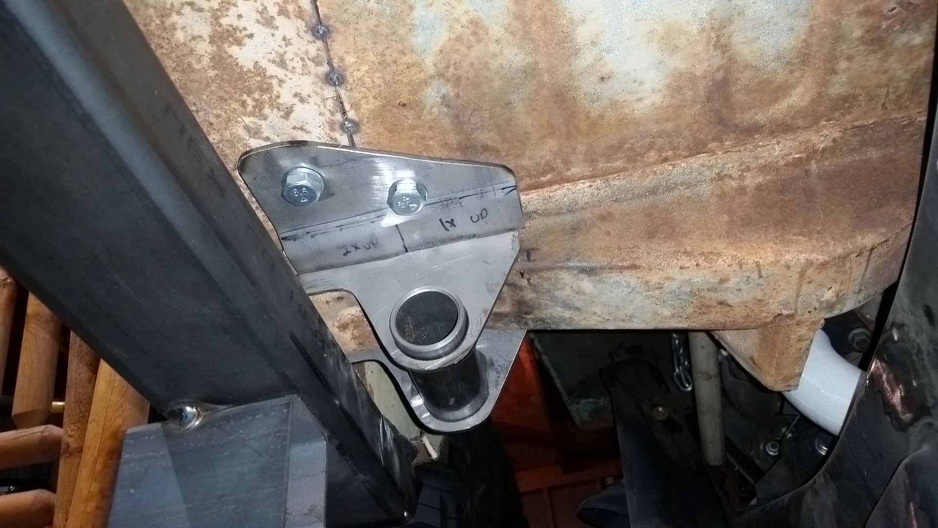
The body side of the mount is all fabricated. I need to tack everything on the vehicle and then spend a few hours TIG welding it up. Fun Fun.

The outrigger parts should be much the same as the passenger side. I already have templates for those so it will just be checking/changing the mounting hole locations which is bound to be slightly different.

I guess I will probably be waiting on my dimple die set....darn. I can still start to make the top and bottoms however. I think I would dimple die them just before welding.
 
I thought about cutting some of the door opening structure, but I really want to be able to run a 'full' door on this thing when I am done....
I will probably be building my own 2pc aluminum hard doors with sliding glass uppers like you would see in an old rover. Something like that.

Do you have a thread on this FJ40 build. I need ideas!

Doors are nice. This guy didn't want them...ever. I like options though so if it were my personal rig, I would do it like you did yours. On my personal Land Rover I didn't even go though the floor. I bolted the roll cage to the A-pillar with 4 GR8 bolts per side. The Rover A-pillar is robust and bolts directly to the frame.

Here the thread on that FJ40: http://www.expeditionportal.com/forum/threads/140955-FJ40-Build-thread-Hell-s-Kitchen

It didn't get very far here on ExPo. Not a lot of interest in buggy type builds I guess.
 

Metcalf

Expedition Leader


I finished up roughing in the drivers side A-pillar body mount outrigger rocker support. It was pretty much identical to the passenger side. There was a few small differences in where the firewall brace structure was.

Now it's time to pull each side seperately for final boxing and welding....right after I make a pattern for the bottom plate where it will wrap around the radius arm mount......

I also got these in the mail.


In an effort to step up my fabrication game a little bit, I decided I should have a good set of dimple dies. I ordered the SPC/Light Racing 5-pc set. That set was very broad and fairly affordable. It included a 0.75, 1.0, 1.5, 2.0, and 2.5 die. I would rather have a slightly larger size range rather than a die that was only 1/4" larger than the next.

I will be using these to fancy up the boxing plates for the outriggers. The 2.5" die is a little larger than I anticipated, so it looks like the 2.0" die will be my go to unit for these 4" wide outriggers.

My hope is that the dimple die holes will allow me to wash junk out of the outriggers. With the position of the body mount it didn't seam to feasible to box them in completely and make them water tight.

It will be nice to be able to fabricate and weld the boxing plates off the vehicle. Using the frame pads seems to be a very good idea for this kind of stuff.
 

Metcalf

Expedition Leader
Some more this evening...


I purchased a matching set of Blair Holcutter's to my dimple dies. These things are great! They cut fast, but require pretty high power. The 2" version will bog down my Bosch 3/8" drill. If you don't pay attention they can grab and throw you.....yes they can. You need to watch the pilot. I think just drilling the pilot would be a better way to go vs the center drill they give you. It is hard to break the pilot through without having the teeth grab. Once you get the cutter established and going, they HOG material. I am using the Blair wax also for lubricant. A 2" hole in 10 gauge cold roll takes less than 2 minutes with a hand drill. My little drill press didn't seem to have enough beans for the bigger units.

And a practice dimple die in the same material using my 20 ton press. I was happy that everything remained very flat without having to use all the press had.


A little trick with the frame pads. Attaching a small washer or this little rounded off drop of material to the frame gives you the 3rd reference point when sticking the frame plate back on the frame after welding/finishing. Once the frame plate is back in place and welded, you can grind the tack welds off to remove it.


My planning for the body mount outrigger rocker mounts seems to be working out well. I was able to lightly jack up the body on one of the old hat channels, pull the two body mount bolts, and remove the rocker sub assembly.

Because of the way the body mount bolts are orientated and inline with each other, you can jack one side of the body without binding anything.


I have been thinking about how I wanted to finish off the outrigger 'box' section since I started on this project. Because of the way the body mount bushing is down in the mount, you can't just stick a plate on each side.

On the bottom, I didn't want an exposed weld seam, to rock impacts, on the 90 degree bottom corners. I decide to fold a U-shape bottom cap that will move that weld up away from the corner about 1" with a double laminated section. I will be able to weld the inside seam and the outside seam. This should make that part of the structure very durable. The exposed corner will also be slightly rounded to help things slide a little better.

I had to make a few test bends to dial in on the proper fit that I wanted for that panel.


Once I had an idea what the bend measurements where, I could lay out the full bracket, cut, drill, clean it up, run it through the press brake, and then dimple die the two holes....

I built the bracket slightly longer than I needed so I can trim it do fit. That will probably take a bit tomorrow.

I will need to weld that panel in place on the INSIDE before I can add the 'top' boxing plate that will be under/around the body mount assembly. This is like chess sometimes!

The B-pillar mount will get the same treatment, but it is much more compact.

After all that is done, I can prep the frame for welding and stick this rocker assembly back on. Rinse, repeat on the other side....
 
Last edited:
Watch out, he's got dimple dies now.

I want to have some dies made that punch the hole and dimple in one process. I've even though about custom shapes to help retain the OEM character of my builds. Speaking with some tool and die makers, it's possible, but expensive.
 

Metcalf

Expedition Leader
Watch out, he's got dimple dies now.

I want to have some dies made that punch the hole and dimple in one process. I've even though about custom shapes to help retain the OEM character of my builds. Speaking with some tool and die makers, it's possible, but expensive.

I will try and use them tastefully....

I have made ones for odd jobs in the past, I finally had to break down and buy a 'real' set.

The Blair Holcutter's are the other part of the puzzle. I have developed a distaste for most hole saws lately. Part of the problem is that I need a much more beefy drill press ( or a knee mill! ).

Fun stuff!
 

Simons

Adventurer
I like the look of those Blair Holcutters, how true to size are they? The problem I seem to have with most of the cheap hole saws I use is the run out always seems to add an 1/8" or so to the final size.
 

Metcalf

Expedition Leader
I like the look of those Blair Holcutters, how true to size are they? The problem I seem to have with most of the cheap hole saws I use is the run out always seems to add an 1/8" or so to the final size.

I can measure next time I cut a hole, but all the holes so far where pretty dang tight on the dimple die stem. I would say less than .03" slop.
I will measure next time, I have lots of holes and dimples to make.
 

justcuz

Explorer
Brennan,

Thanks for bringing this thread over here.
You may not get the views and comments you receive elsewhere but it does not matter. Every body can appreciate great creativity when they see it.

Your modesty about your wild land career is not really being honest with these folks.
Anyone who has done that job knows that to be a crewman or jumper for 10 years you have to be a bad azz.
I just got back from Tahoe from our reunion, had a great time telling stories about fires and people we forgot over the years.image.jpeg
 

justcuz

Explorer
Plans for water, mud and debris drainage out of the brackets? Plans for skids on those brackets, like a mini boatside?
 

Metcalf

Expedition Leader
Plans for water, mud and debris drainage out of the brackets? Plans for skids on those brackets, like a mini boatside?

It's hard to see, but there is a 3/8" drain hole at the low point of each outrigger box near the frame plate. That should allow me to flush them out with a pressure washer. They will gather mud, but I didn't want to try and make a completely closed assembly. The vertical sides extend past the hat channel on the A-pillar and would have trapped a bunch of junk with nowhere to go.

The outriggers are 10 gauge cold roll sheet. I doubled up the exposed bottom corners where rock contact would be likely. The bottom cap has a folded 1" flange that moves the 'corner' weld seam up on the side where it shouldn't be hit. I also fully welded the inside seam. That should give me a durable corner that is over 1/4" thick. It also gives me a slightly rounded corner rather than a weld or overlap corner.

No plans for boatsides on this one. With the splayed frame it would have been a pain and/or I would have had to give up some support structure on the B-pillar to make a single plane boatside panel. The body this car is really narrow compared to the track width and frame width. The rocker bars, even being offset from the body about 1", only hit the 1st lug on the tire. The rockers are also tucked up pretty high, I gained almost an inch of clearance from the stock FJ40 sheetmetal rocker location. From the bottom of the frame to the bottom of the rocker tube is a 5" vertical difference. The frame is only 6" tall in the belly section. I don't suspect the rockers will be seeing THAT much damage unless I do something really stupid. They are a little overkill also. I used 2x3x3/16" A500 material for them, I probably could have gotten away with 1/8" wall honestly, but it is a little extra insurance. I am also using the same stick of material for the front and rear bumpers....
 

njtacoma

Explorer
wow those look good!

watching and learning. I enjoy the way you share your thought process, it allows me to understand the thinking that goes into the decisions you make.
 

Metcalf

Expedition Leader
wow those look good!

watching and learning. I enjoy the way you share your thought process, it allows me to understand the thinking that goes into the decisions you make.

Thank you.

I have been working on the 2nd side, it was just as much work as the 1st side! I am surprised how much time I have in these assemblies. They serve a lot of functions, but dang, sometimes even I am surprised by some of this stuff.

It will be nice to be able to move onto a new part of the project...
 

Forum statistics

Threads
186,602
Messages
2,887,917
Members
226,715
Latest member
TurboStagecoach
Top