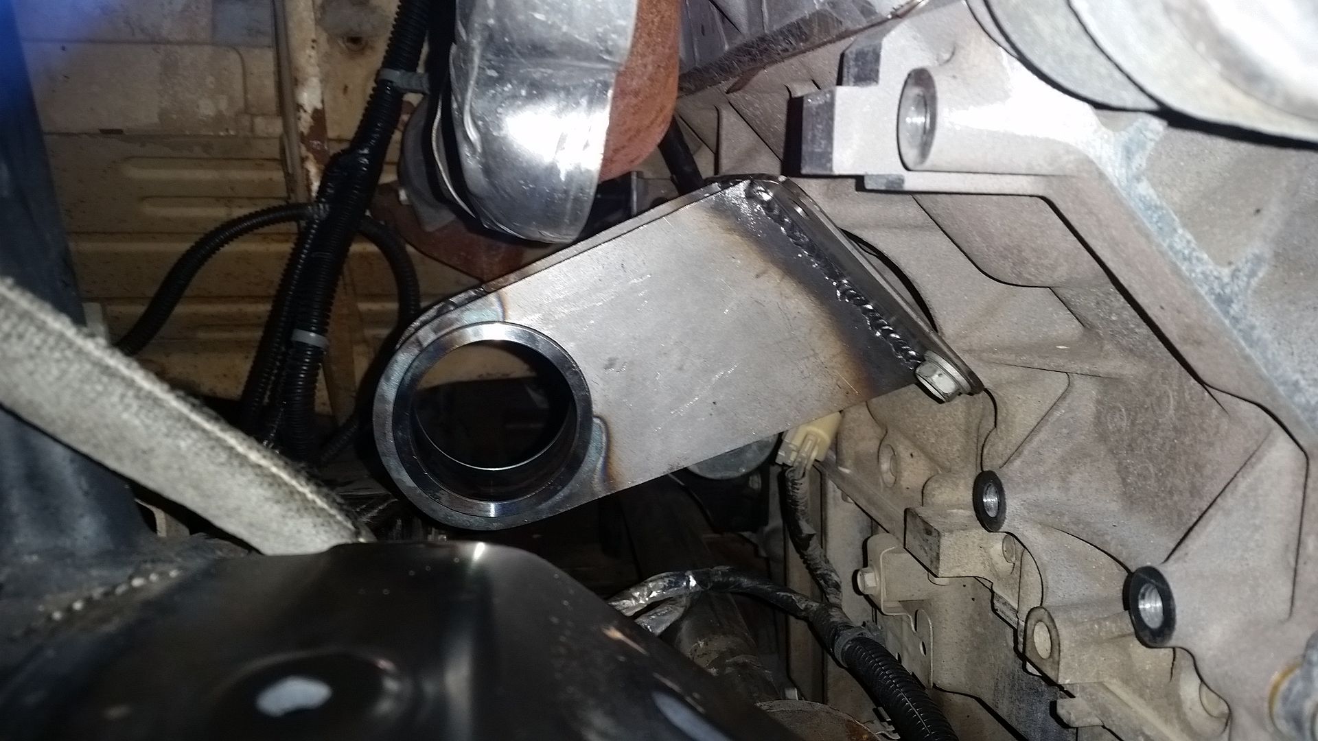
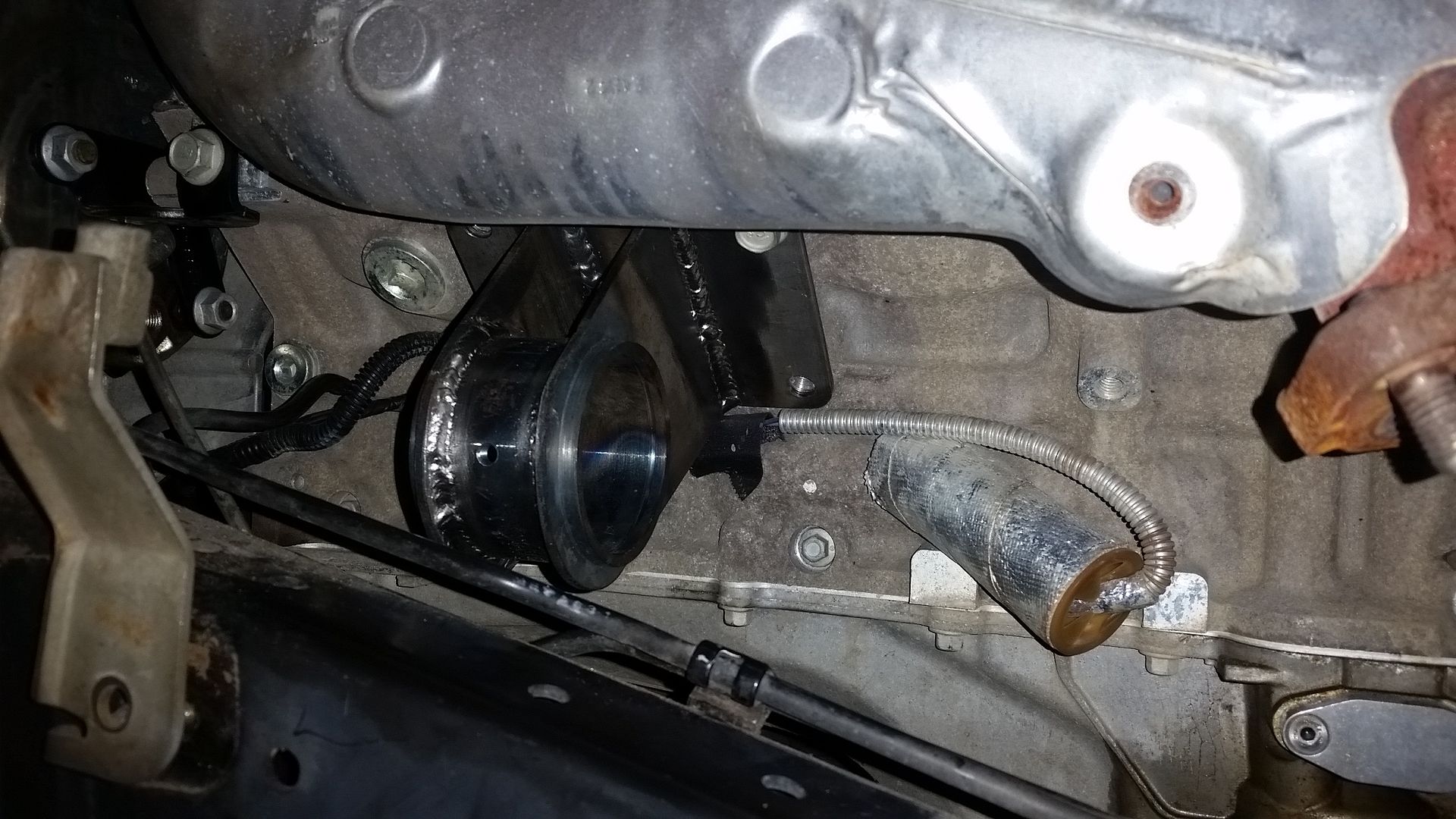
Blender, My LX450/FZJ80 + FJ45esk + GM + Land Rover crazy concoction

Metcalf

Expedition Leader
hmmmm if you just had some Volvo Portal Axles....

While I would love to play with a set, I think the the car would just be too tall. I am half way lamenting about having to run 2-3" of 'lift' right now to clear the 40" tires.

Some day I would like to design a chassis from scratch that could use portal axles with a very low stance and high belly. That would be very interesting. I have a feeling the engine placement would need to get pretty exotic to clear the front axle and front driveshaft. I have always wondered about running a flipped high pinion diff with a 2 gear portal axle. Depending on the differential you could almost completely negate the change in front driveshaft clearance in the chassis with the added 'lift' from the portal axles. Gearing has always been an issue with portal axles for road speeds also....and the gear boxes don't exactly like going 80mph down the interstate!

Fun to think about though!

Truth be told, large tires provide a lot of ground clearance ( and flotation ) on a much more simple and lighter weight front axle. If you where to ditch the previously conceived ideas on where the rear differential needs to go, you can get some even more amazing clearance out of the rear axle. In general, it's much easier to pick the patch for the front axle rather than the rear, it needs more help because you can't steer it around most obstacles typically. We could always through ever trick in the book at it.....portal axles, extreme offset rear axles, rear steering, etc! That would be kinda fun.
 

skibum315

Explorer
Oh sure ... as if I needed another thread to follow. Sheesh ... and a good one, at that, by the looks of things. Oh, and thanks for the reminder (yet again, since I've been following the Willy's and Dodge threads for a bit, now) that I need to get cracking on a few of the ideas rattling around in my own head ... :smilies27:snorkel:
 

locrwln

Expedition Leader
Awesome build. I have the same tires (size/brand) for my 4Runner build. :sombrero:

IMG_0859-L.jpg


Those are in a full-size chevy bed...

Jack
 

Metcalf

Expedition Leader
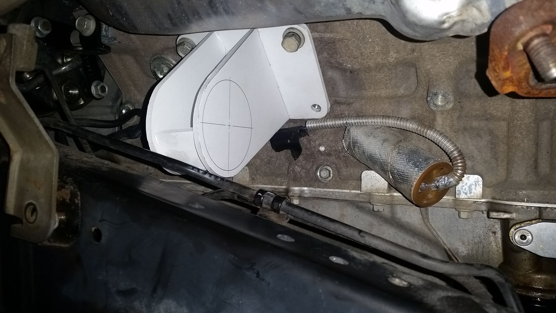
A quick round two on the engine mount mockup this evening...


I changed the lengths of the mounts slightly to make the relationship to the frame the same. I also dropped them slightly to get the mount close to the frame corner. This should make the frame side of the mount fairly minimal and simple.

Tomorrow I will try and turn the templates into metal and weld then up into a sub-assembly. I should have some aluminum coming early next week so I can make some setup bushings for the joints. Then I can move onto connecting the engine mounts to the frame....yipee. It will feel really good to have this thing hanging off the frame!
 

Metcalf

Expedition Leader
Motor Mounts Part 1

Sometimes the little things take the largest amount of time. This is how I burned up my Saturday...


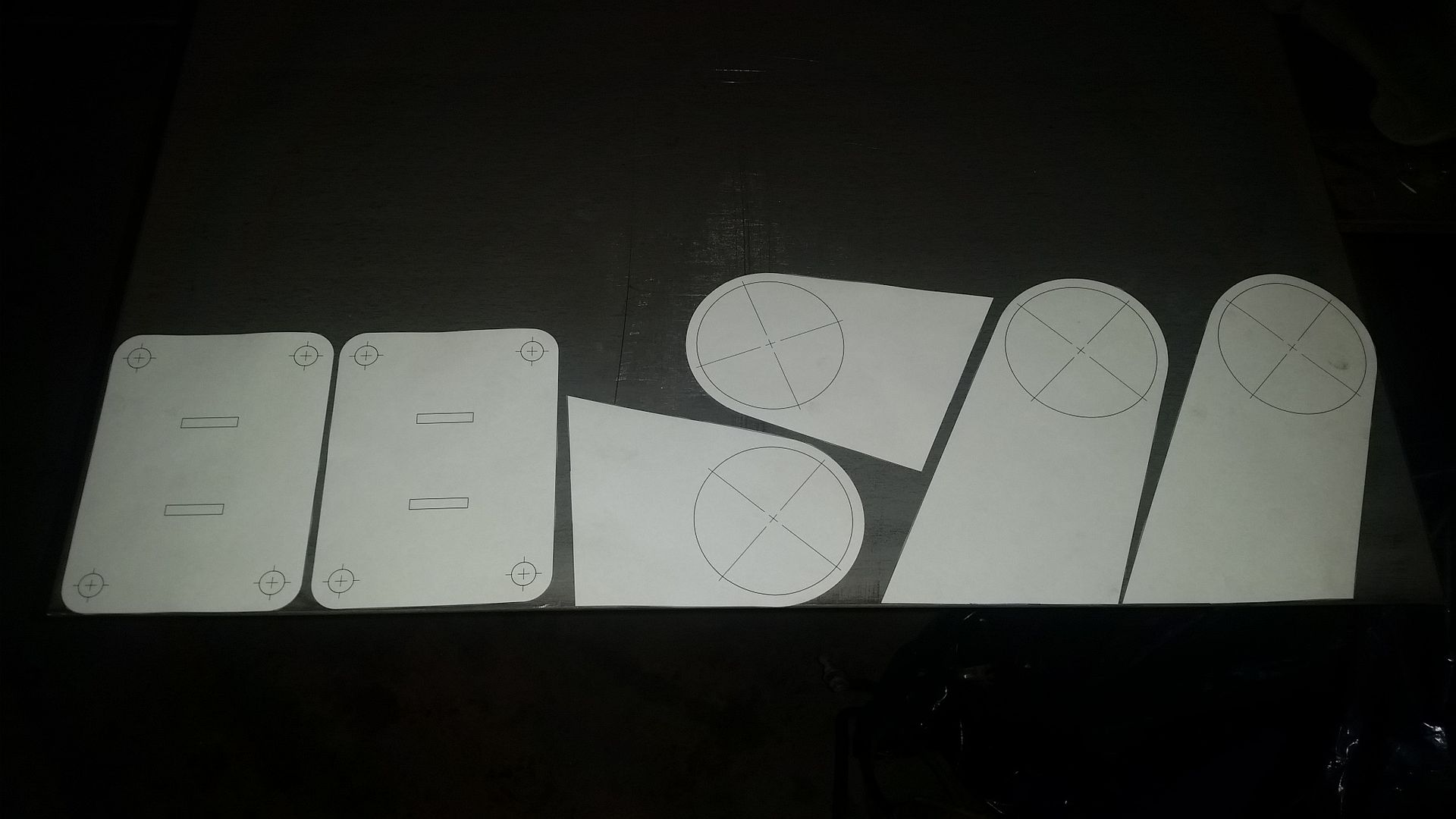
More paper templates.

I am using 1018 Cold Roll 10 gauge plate. I had the steel supplier cut the sheet in to 2x4 panels. That is a good size for me to move around. Note to self. They shear it. That leaves a very sharp edge. Sharp enough to slice your hand. From now on it's worth hitting the edges of a new panel with a flap wheel. I almost ran out of band-aids.


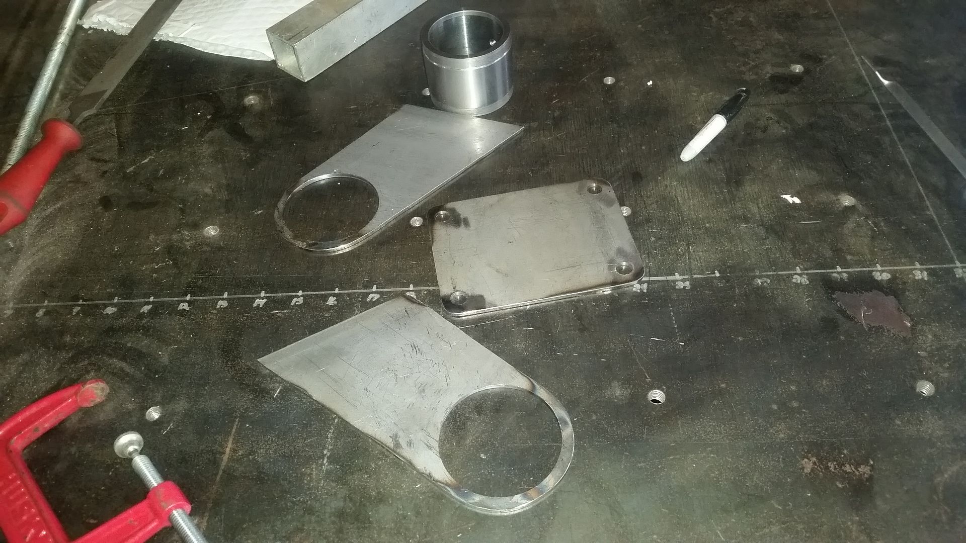
After much drilling, cutting, sanding, and cleaning you end up with a pile of parts like this.

I usually group the shapes I need to cut into a section I can cut off the main plate. Then I center punch and drill out all the holes for that group of parts. Then I rough cut the single parts out with a variable speed jigsaw with a good quality Bosch metal cutting blade. I then clean up the outside of the parts on my 12" disc sander (I love that thing, it's a beast!). The inside of curves and circles are cleaned up with a small flap wheel on a grinder.


It is always a good idea to test fit parts before you invest too much work in them. I checked them in the model, they fit. I checked them in steel also, they fit. I am happy.


And then bingo you have motor mounts, after spending a few hours setting everything up, jigging the parts, and welding everything.

I still need to add a gusset on the top of each mount and a strip of material to close in the bottom maybe. I also need to weld the outside of the joint sleeve. Fun stuff.

Hopefully that will only take a few more hours tomorrow.
 

VanIsle_Greg

I think I need a bigger truck!
Those look very sturdy. I think this is the very first time i have seen someone use rebuildable heims for motor mounts? I dig the concept, and they are very reasonable to rebuild and replace as needed...good call. Likely they will last a very long time in this application.

Love the templates too, quality stuff.
 

Metcalf

Expedition Leader
Those look very sturdy. I think this is the very first time i have seen someone use rebuildable heims for motor mounts? I dig the concept, and they are very reasonable to rebuild and replace as needed...good call. Likely they will last a very long time in this application.

Love the templates too, quality stuff.

Thank you.

I think the Johnny-type-Joints will be interesting to use. I got the idea from here...

http://www.pirate4x4.com/forum/gene...6-savvy-currie-koh-mod-jk-3.html#post20437577

My hope is that they allow some misalignment rotation when assembling things....and to help with chassis flex. Swapping out the bushings is easy enough. I made sure to make the bushing on the removable part so that I can do it on the bench. Since I am going to be using these same joints for both the engine and transmission, I will throw a rebuilt kit in the spare parts bag. The joints are captured which should be nice and save if things where to go sideways.

The isolation the joint provides is my main concern. I hope it will be tolerable. I used a common 2.63" wide bushing so I could rebuild the mounts to use a lot of other bushings, including the Rubber lower control arm bushings from a Jeep TJ/XJ which is probably the softest option.
 

Metcalf

Expedition Leader
Motor Mounts Part 2

How can something as simple as motor mounts take two days to fab!?!
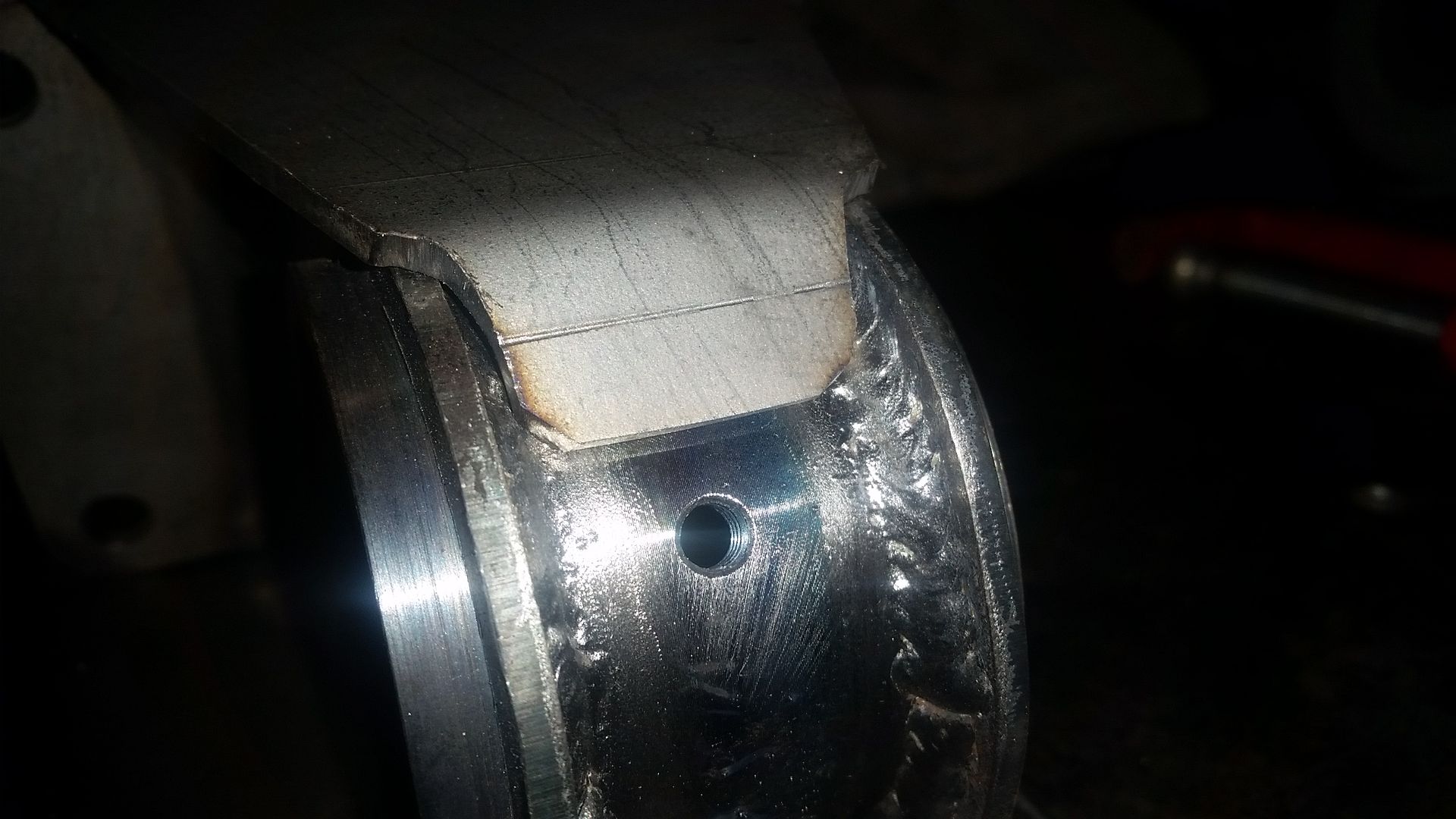


I started out by adding a top gusset to the motor mounts. This was to provide front to back stability to the mount. Because of the design of the main mounting plates, I had to bend the little tongue over and fit it. It was a pain, but worth it in the end.
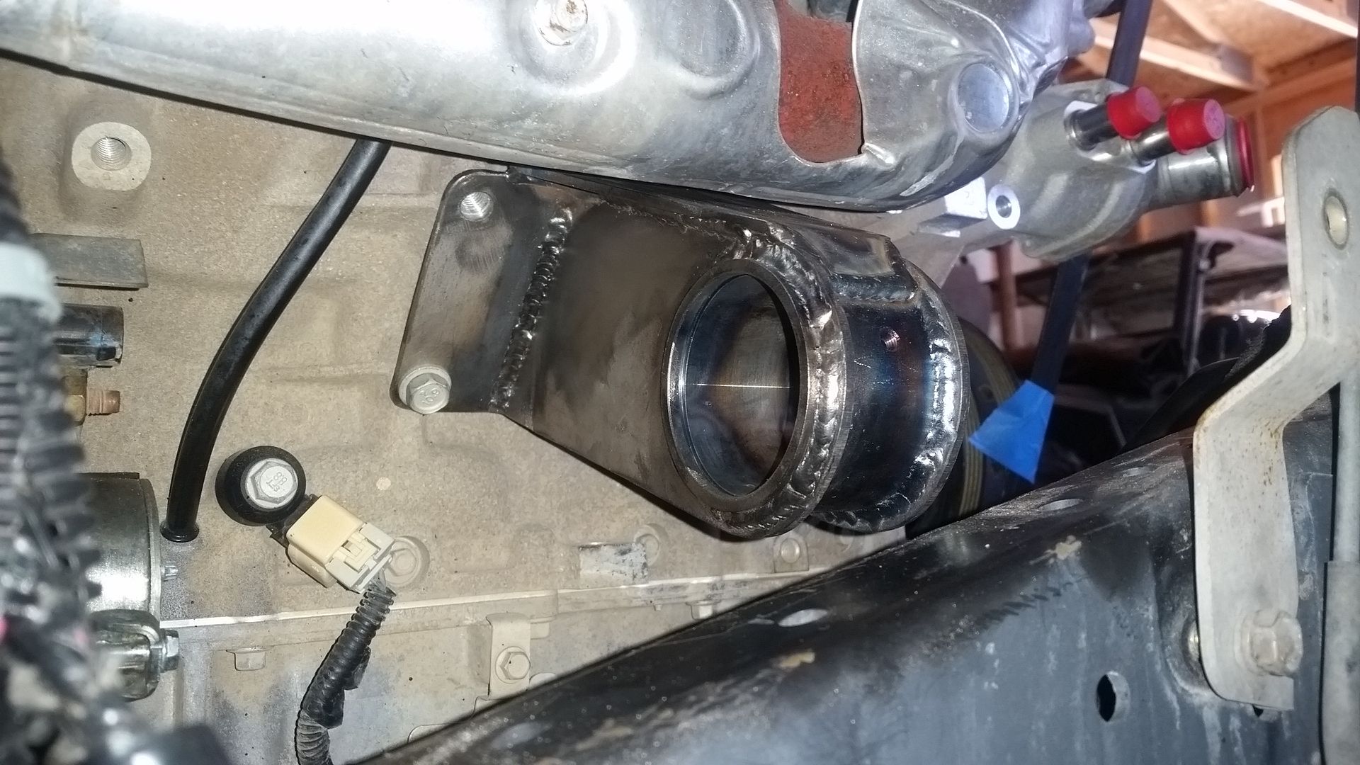
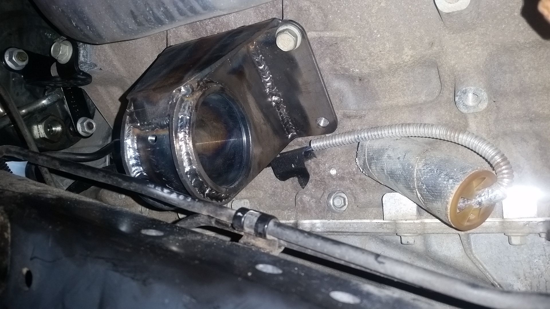


The engine side of the mounts are now done....I think....
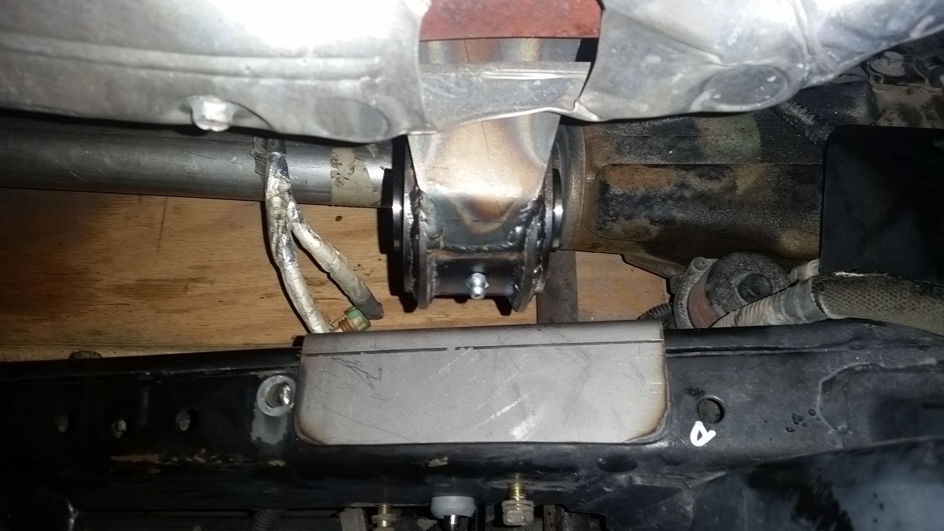


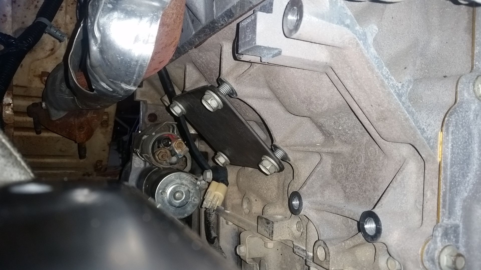
Once the engine side mounts where assembled, I started construction of the frame side. I decided to use a frame pad where the mounts on the frame will be. This allows the mating parts to be fabricated and tack welded in place to the frame pad with everything assembled. Then I can pull the frame pad out with the tacked in place mounts for final welding.
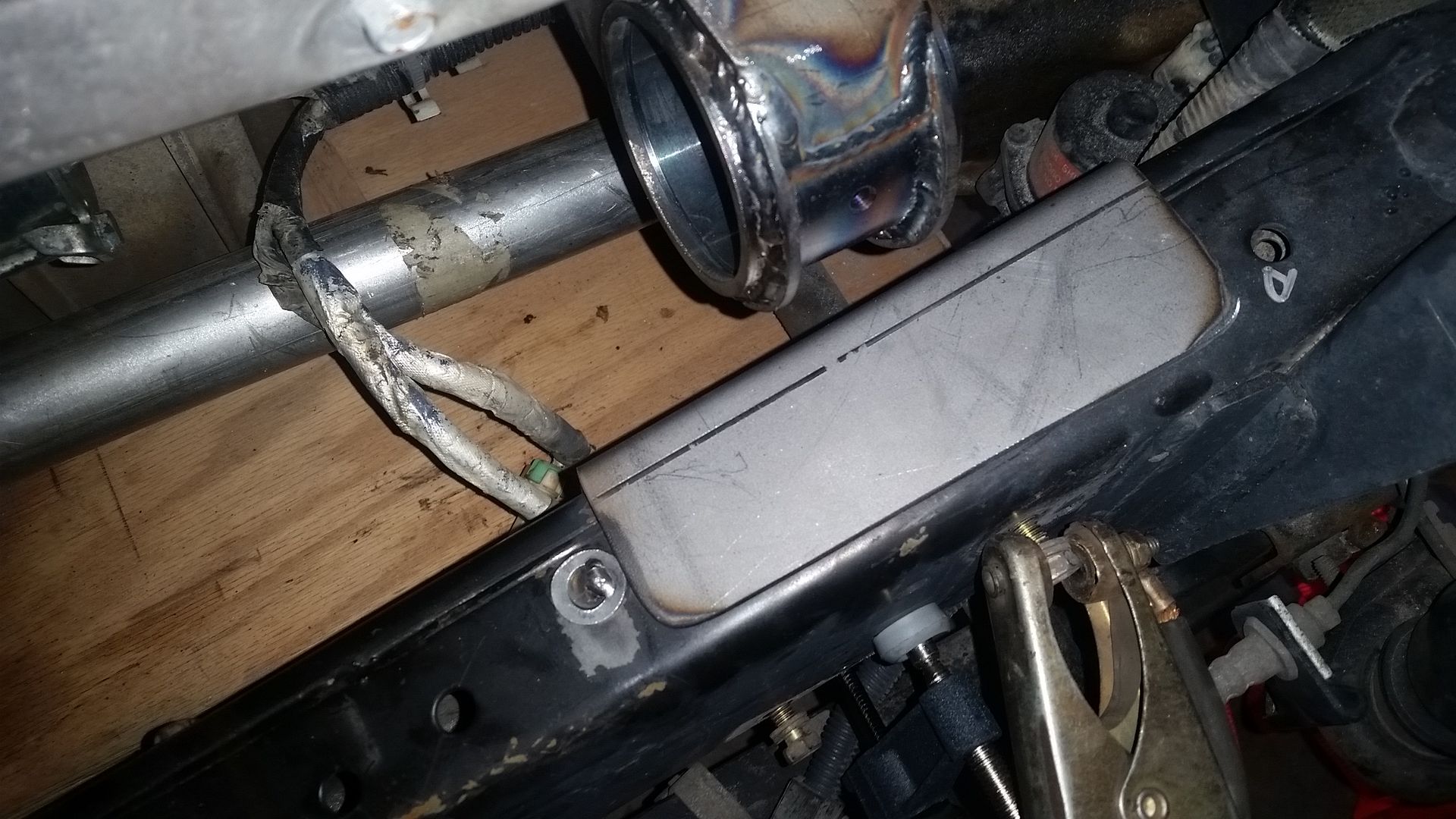


Tip of the day. If you make these frame pads, bend a 90 flange in the top if you have room. This gives you a nice repeatable reference point for the vertical position. The inside is also hard against the frame. The only other direction it can move is fore/aft along the frame.

If you tack weld a washer to the frame, you end up with a nice simple reference point for that direction. This means you can remove and replace the part and not lose the position on the frame. It will hold up to a light hit, or if you need to clean the frame with a scotch-bright pad or wire wheel.
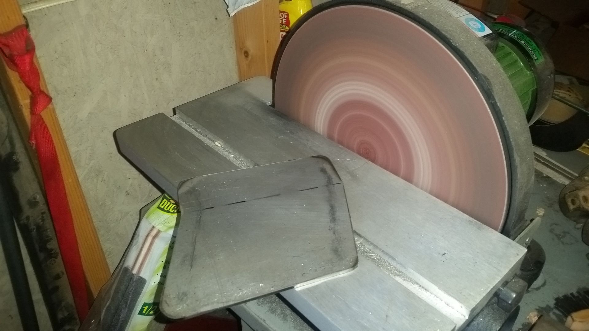


My favorite tool of the day. This is one of those 12" diameter disc sanders from Harbor Freight. For what it cost, FANTASTIC. It is so nice to be able to have a decent platen to square up parts and it also makes fast work of rounding off corners. Highly recommended.


Once I had the engine side bolted in place and the frame pads located, it was time to start connecting the frame to the engine FINALLY!

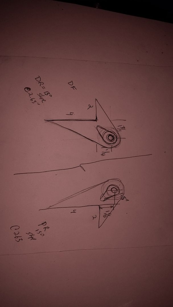
This was much lower tech than the computer. I took some rough measurements. Then made some quick poster board mockups to dial in the position of everything. Once I got within about 1/16" I moved over to foam board.
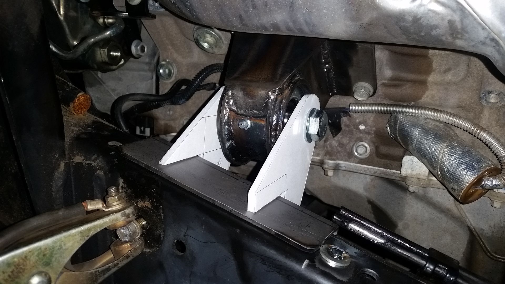
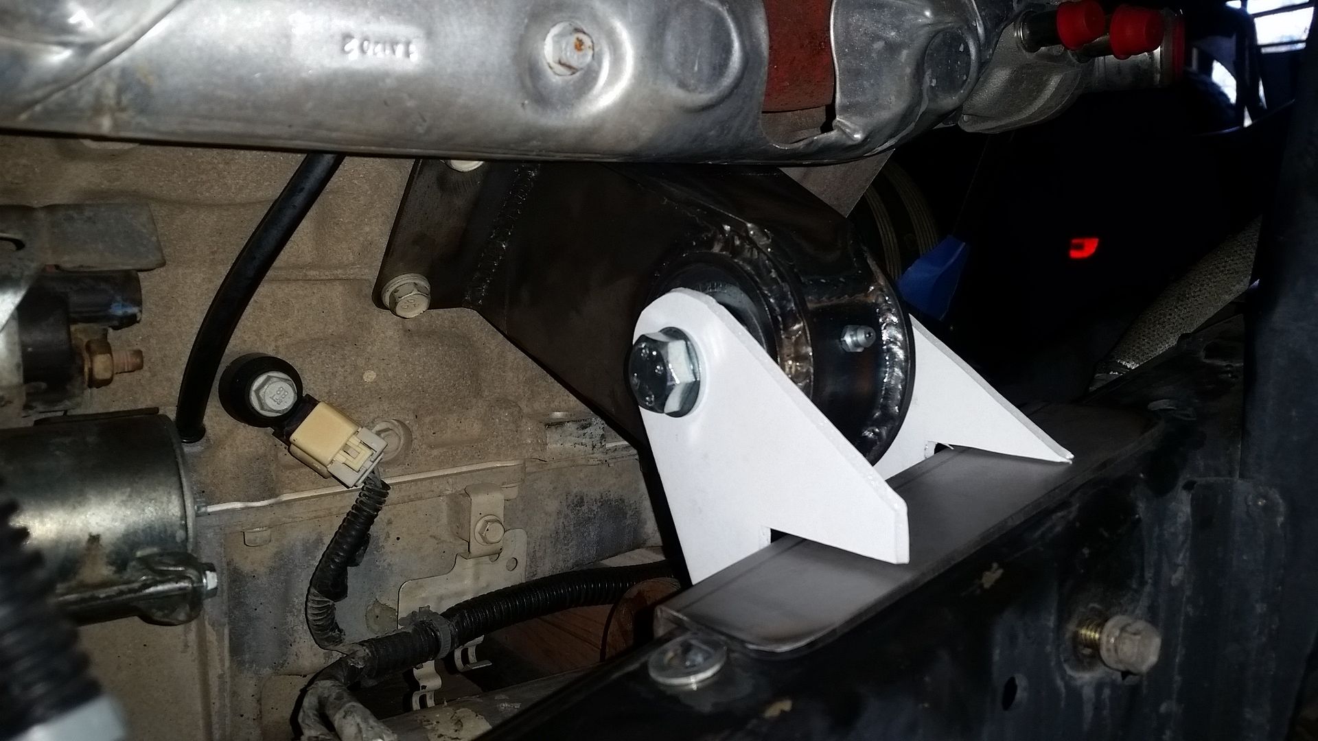


This is where I stopped for the night. I have one more tweak to the frame side mounting patterns that can be done when I turn them into metal. Overall I am pretty happy with how simple and symmetrical the frame side mounts turned out. I think the mounts where within 1/16-1/8" of being the same.

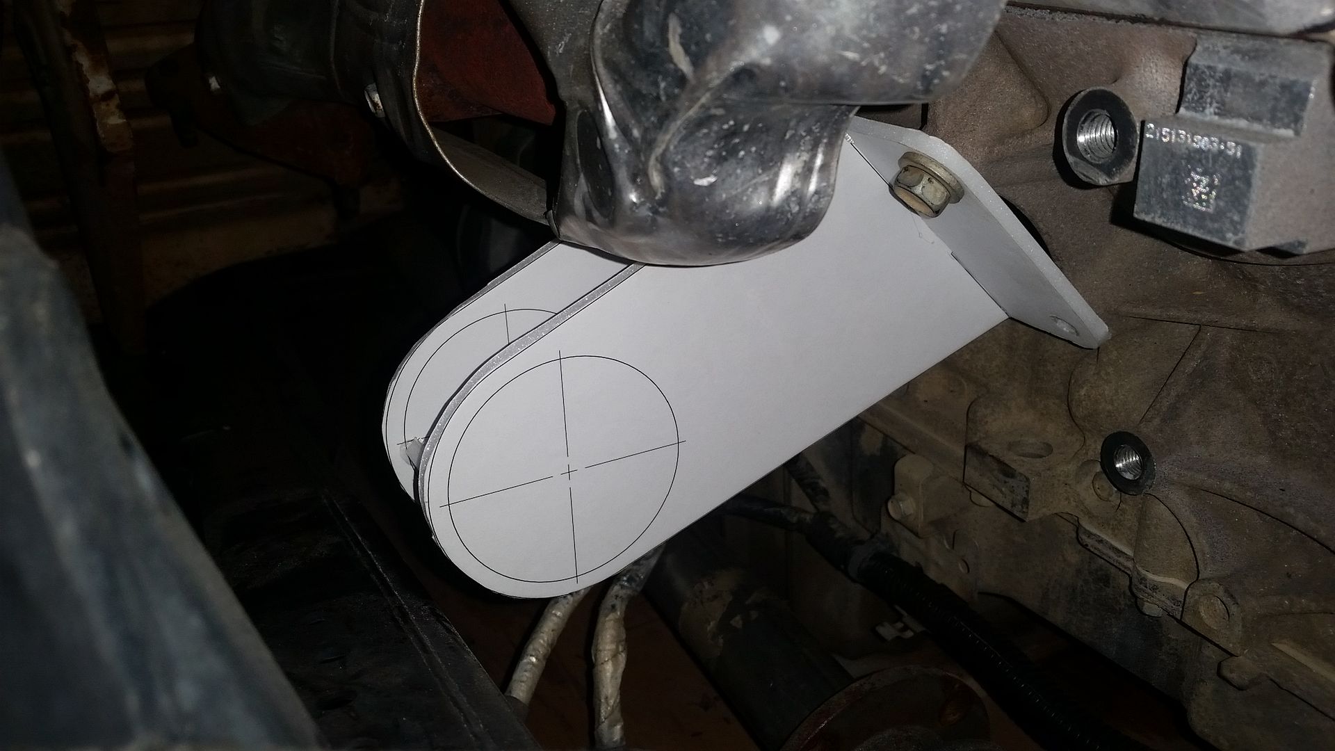
Once these are in metal I will install them, tack weld in place, remove the frame side mounts, final weld them, add gussets, clean the frame where the pad will be welded, and then final weld the frame pads into place. I guess there will have to be a part 3 for motor mounts....gees....little time suckers!
 

Metcalf

Expedition Leader
Nice fab. I dig the upper plate on the motor side mount, lots of extra weld and strength.

Thank you. I am trying to up my fabrication game a little bit on this build. You have to keep learning....

I think the upper plates will make the mounts a lot stronger for the weight. I can't imagine them breaking now. I am really liking working with this 10 gauge cold roll 1018 plate. It's clean, it is easy to work with, welds nice, seems to bend nice, etc. It isn't as thick as you see a lot of people typically fabricate with, but I think it is very much strong enough for well designed parts. The 1018 material should be 50KPSI+, to it is basically the same strength or better as typical 3/16 A36 hot roll plate.
 

VanIsle_Greg

I think I need a bigger truck!
Those look very stout. I imagine with thicker steel they might be stronger, but not by much. Agreed... well designed and fabricated is likely better than over-built and under designed.

I am a complete hack when it comes to steel fabrication. I can't even weld (yet), but I can sure appreciate the effort it takes and how hard it is. Like many things, people who have talent in steel fab make hard tasks look effortless.

:coffeedrink:
 

Forum statistics

Threads
188,244
Messages
2,904,477
Members
229,805
Latest member
Chonker LMTV
Top